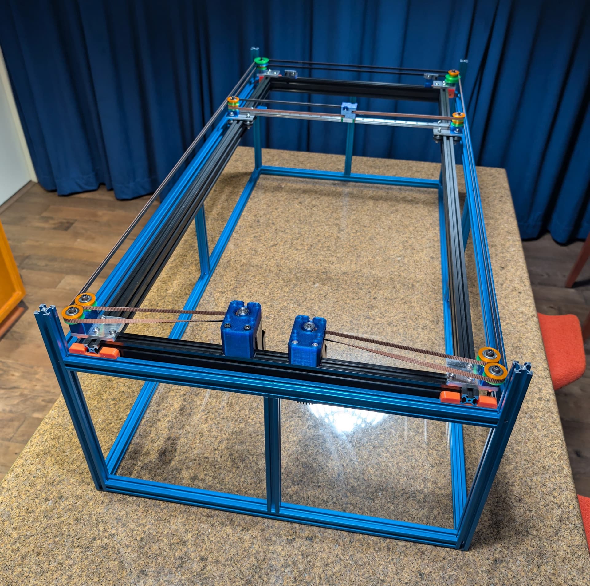
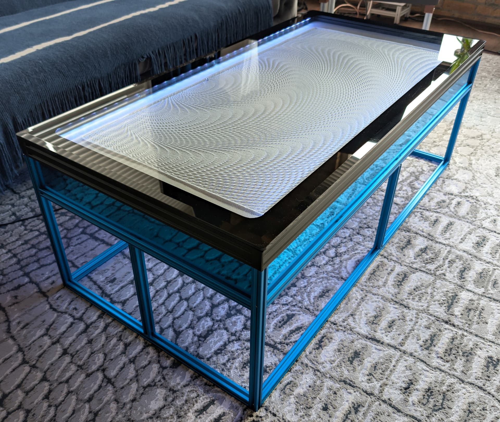
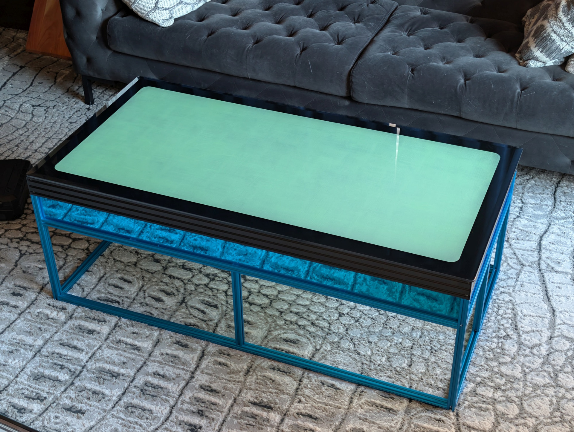
I built a new table to replace Arrakis 2.0, making some changes to the design that I hope will be improvements. The new table uses a 24 x 48” glass top - chosen for slightly smaller size than Arrakis 2.0, and lower replacement cost (I broke the glass on Arrakis 2.0 and it cost $330 to replace it). Arrakis 3.0 can fit through doorways without having to turn it on its side.
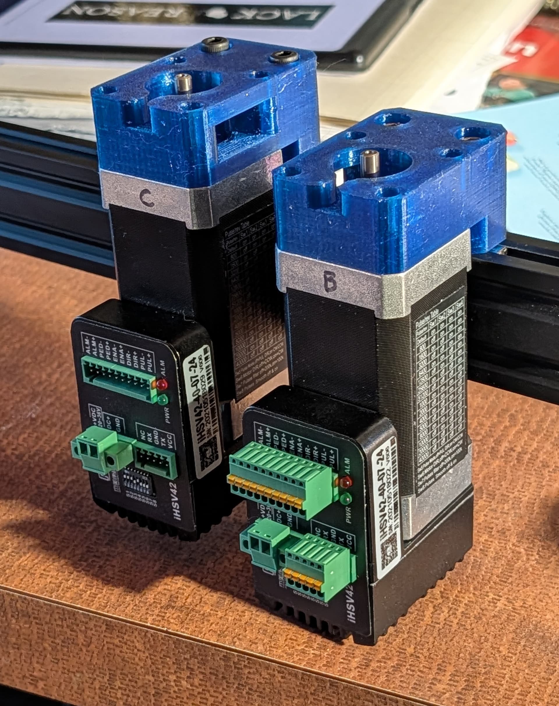
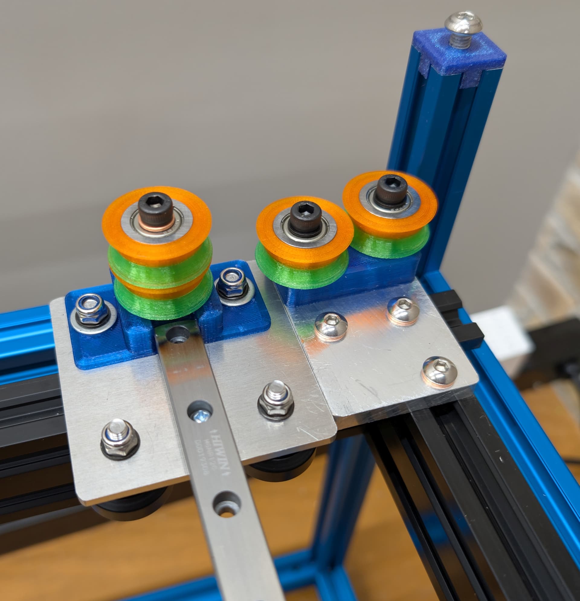
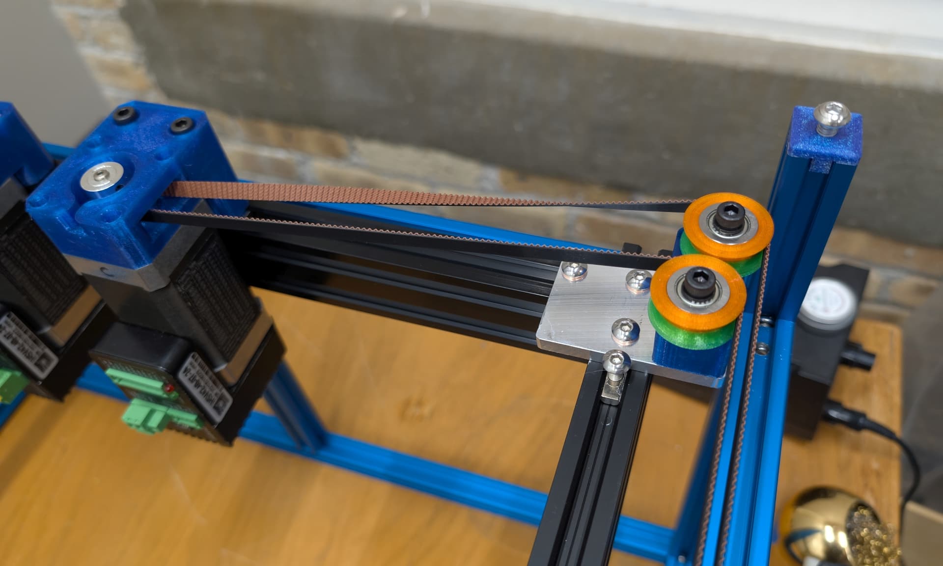
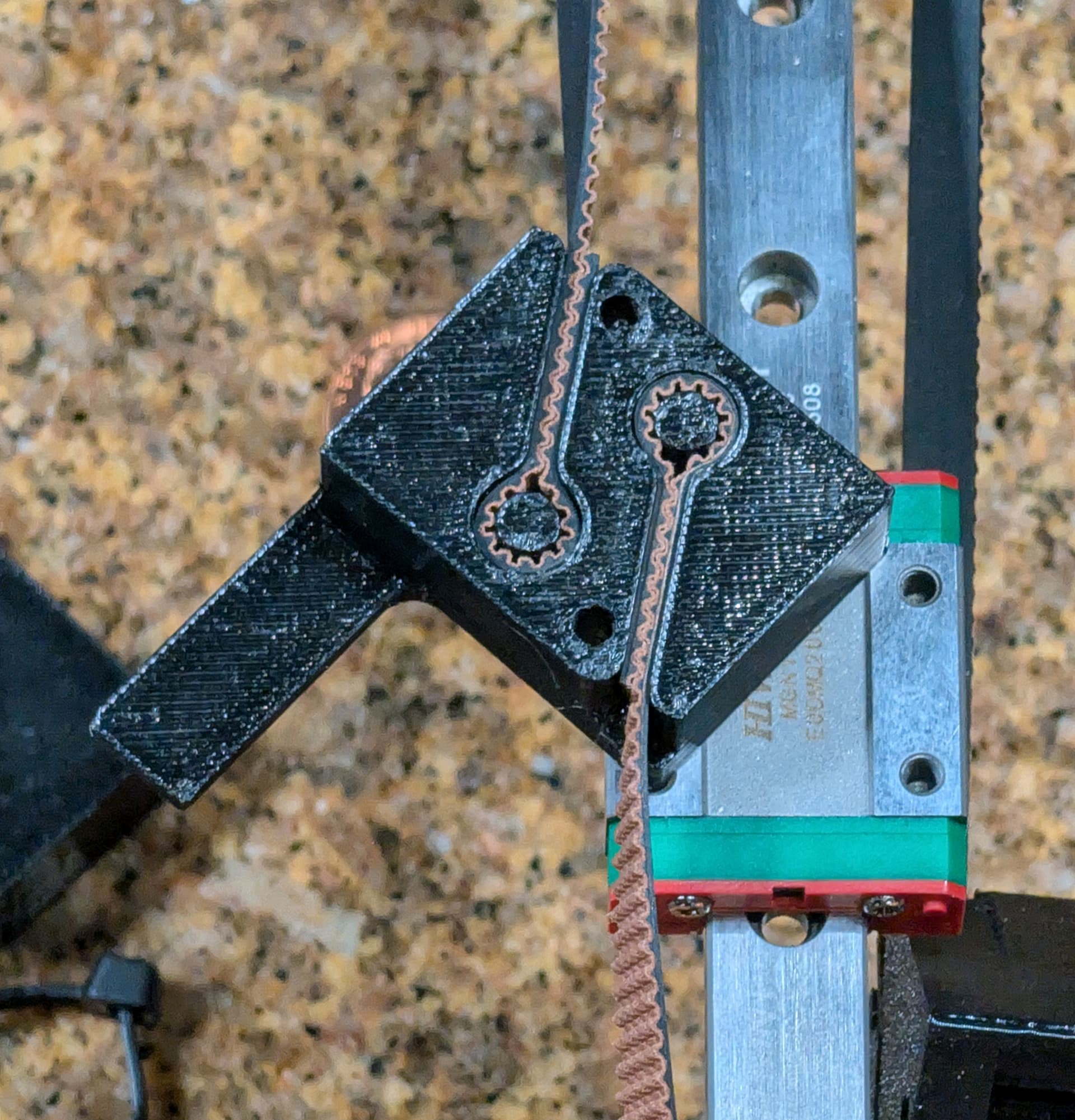
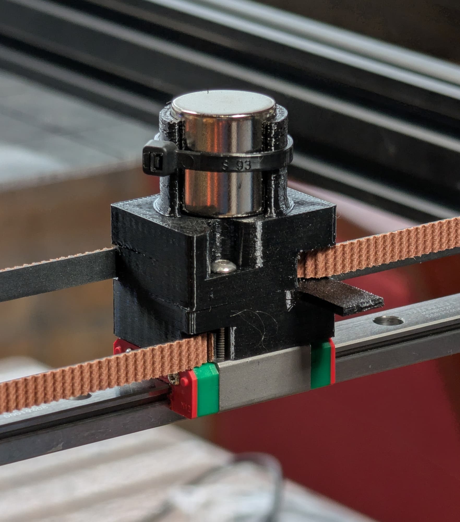
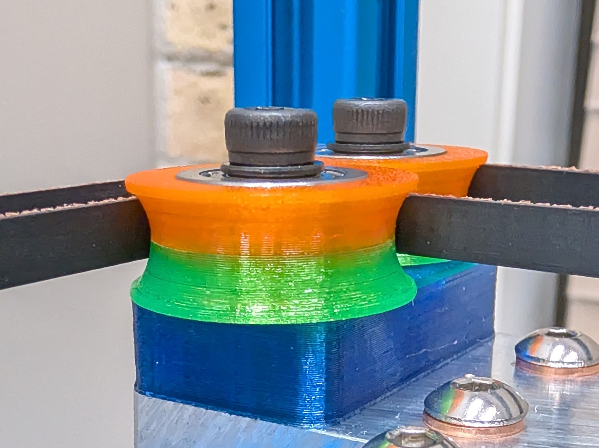
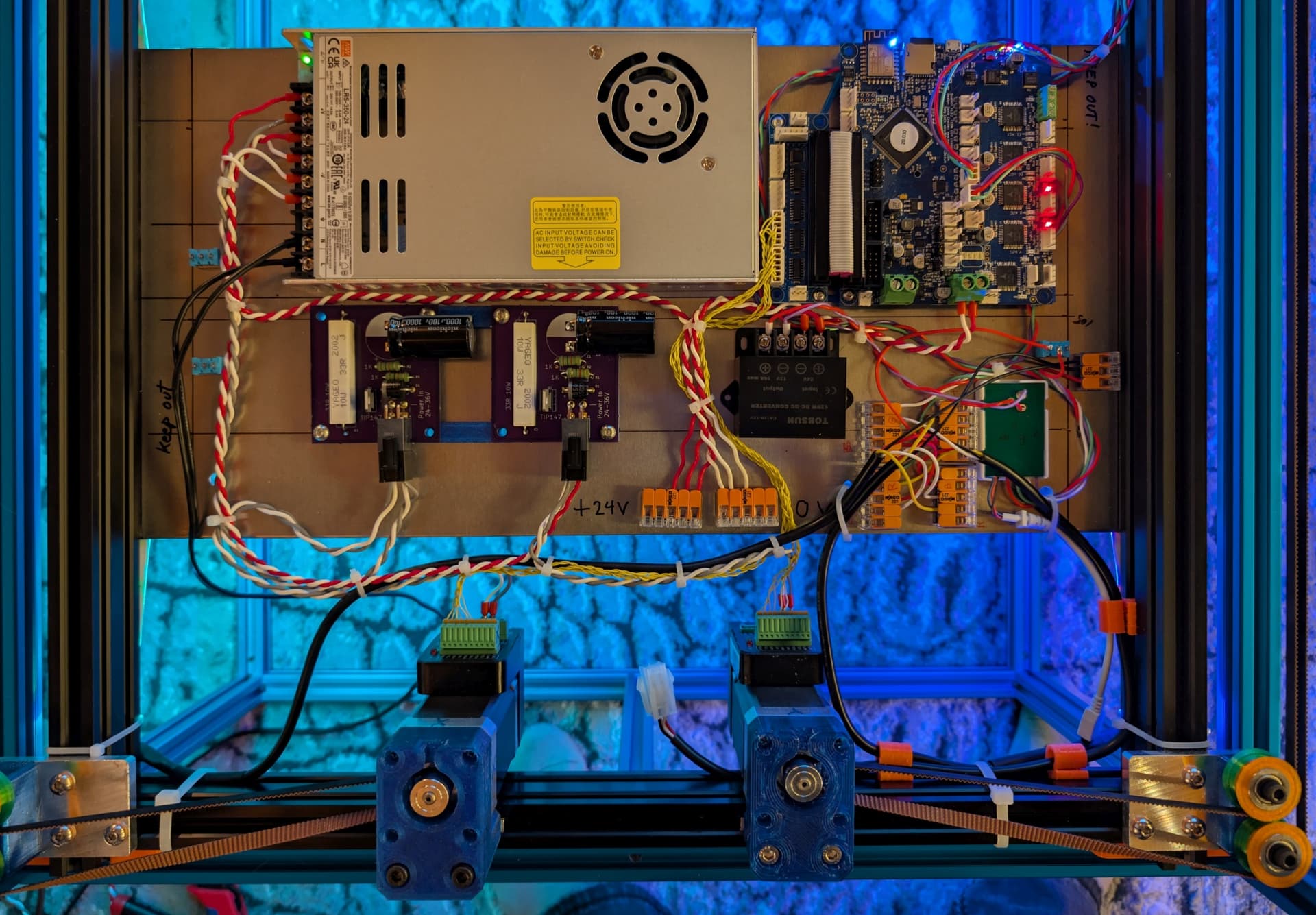
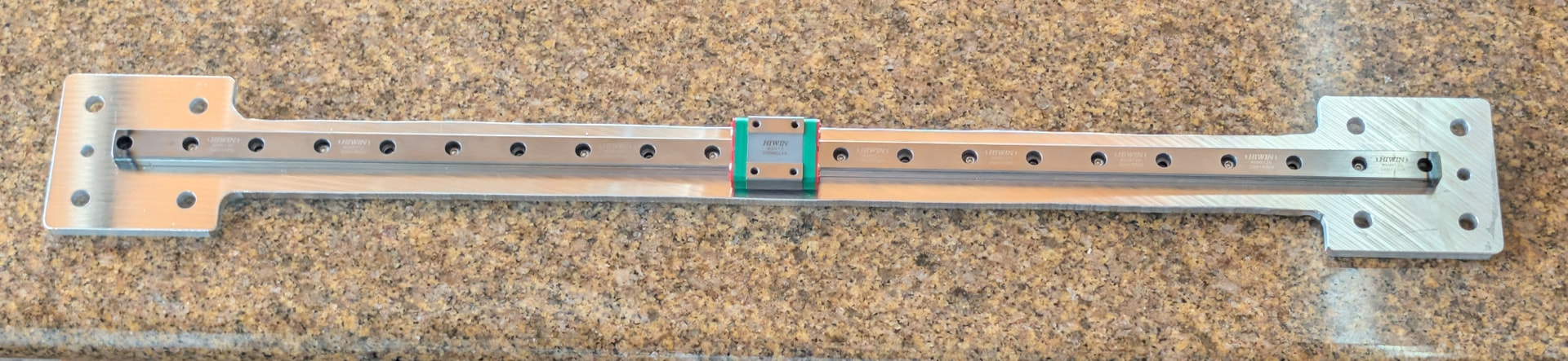
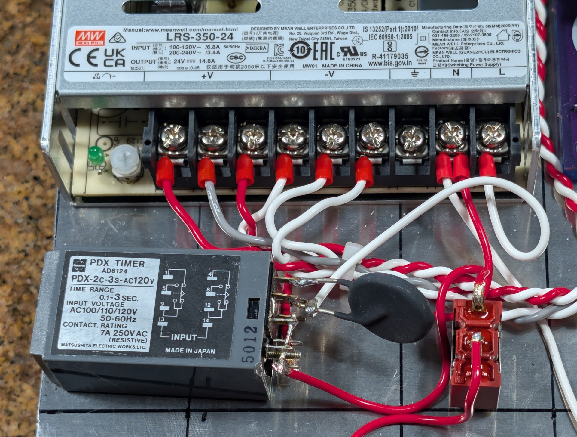
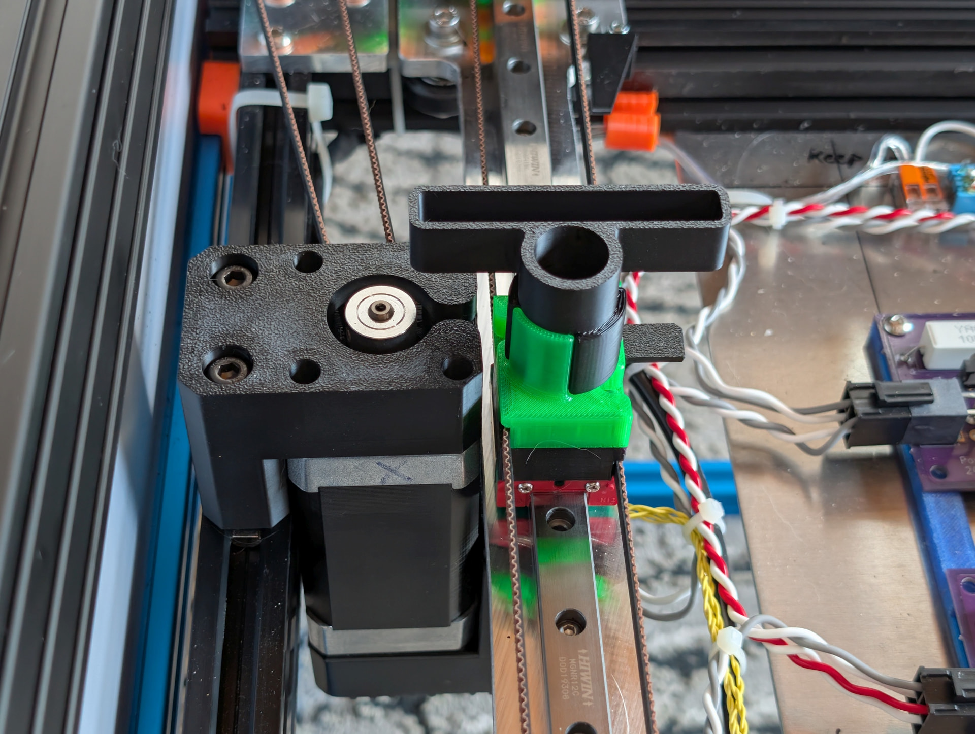
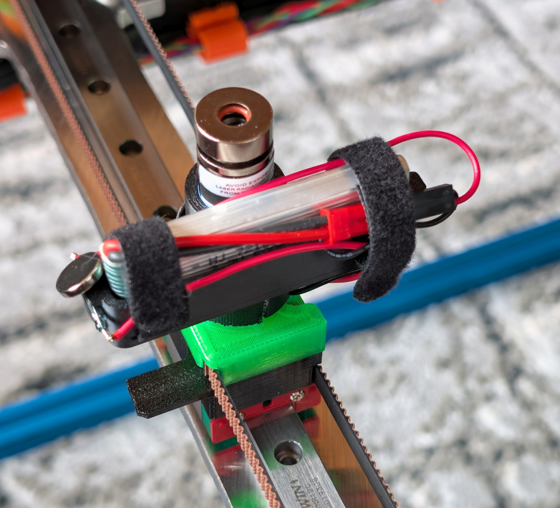
The mechanism is built on a 2040 v-slot frame that drops into a 2020 t-slot support frame that is slightly smaller than the glass top. The Y axis motion uses wheeled carriages that run in the v-slot, with a 12 mm linear guide used for the X axis. I used the same iHSV servomotors and Duet2 WiFi controller I used in Arrakis 2.0 because I had them handy. The mechanism is a stacked belt coreXY type using 3D printed concave pulleys that prevent squeaky noises. The pulleys use stacked F625 bearings. I used optical endstops. Drawing area is 465 x 1005 mm. All the electronics mount on an aluminum plate screwed to the bottom of the mechanism frame.
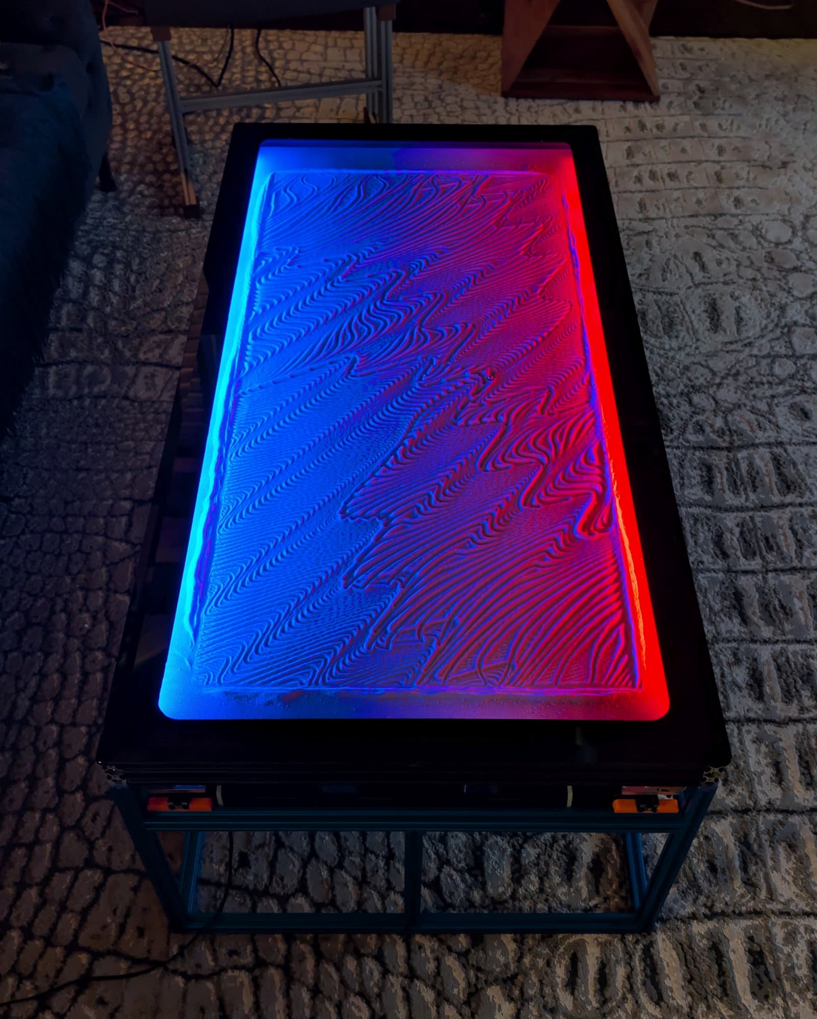
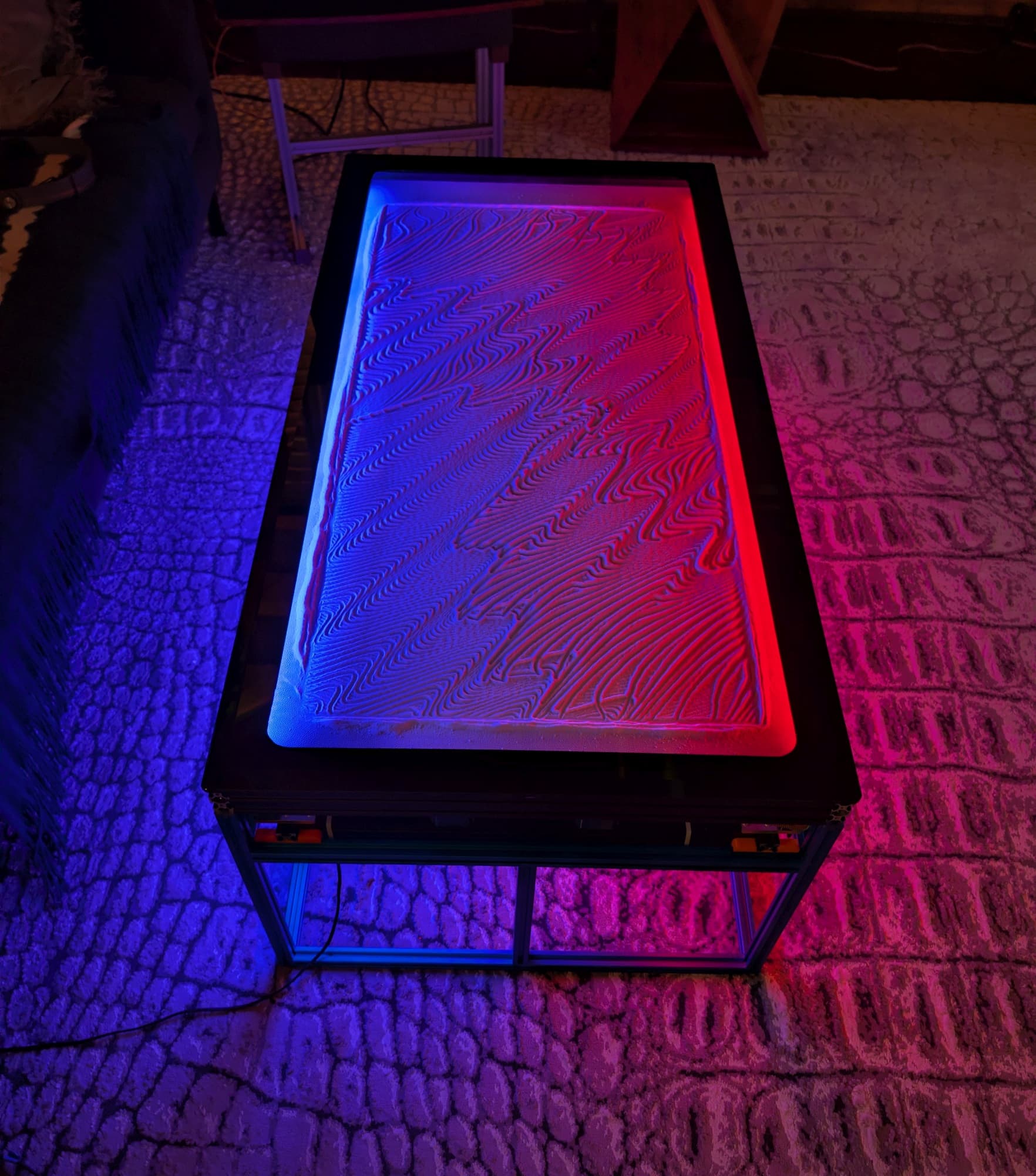
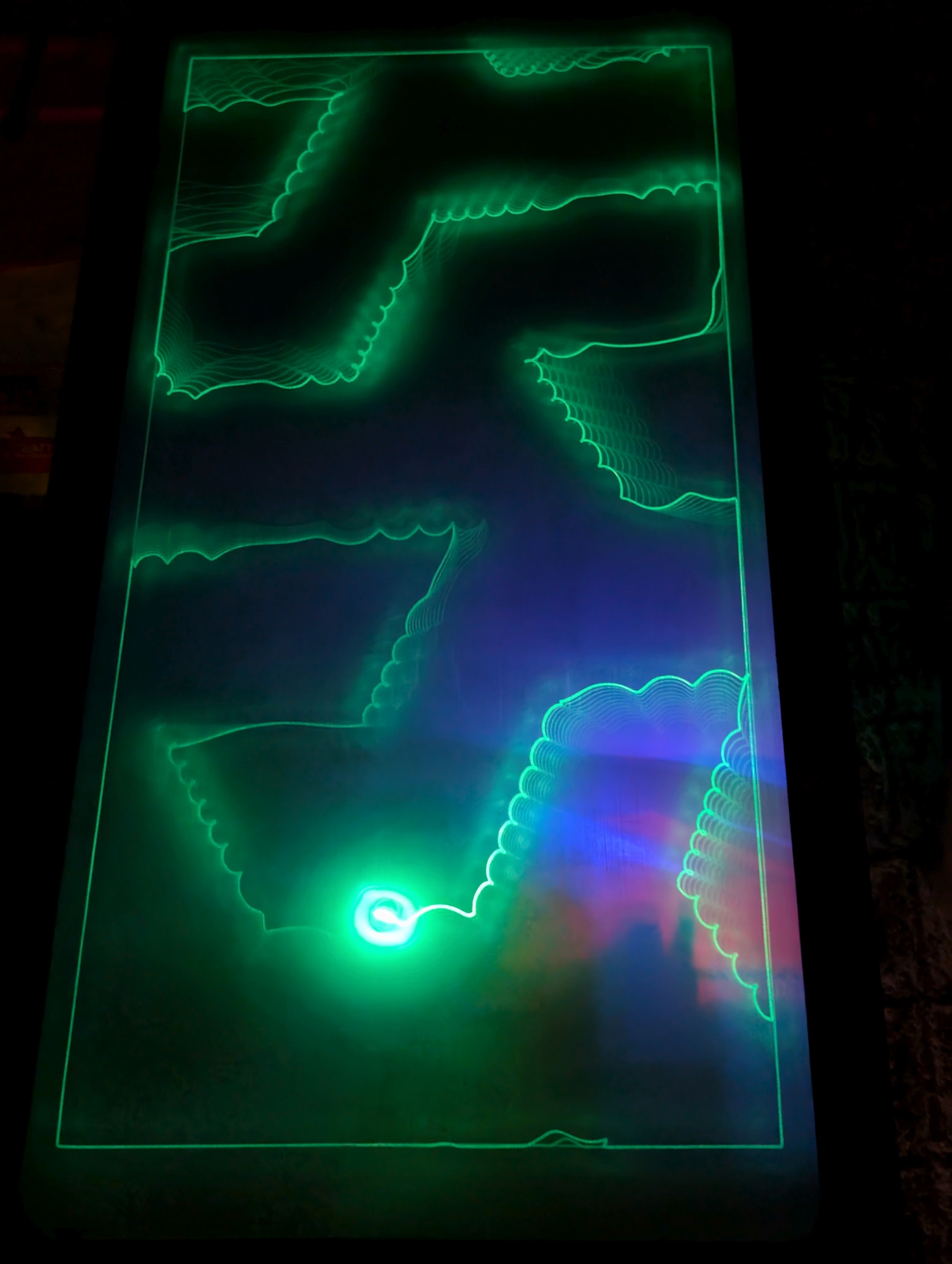
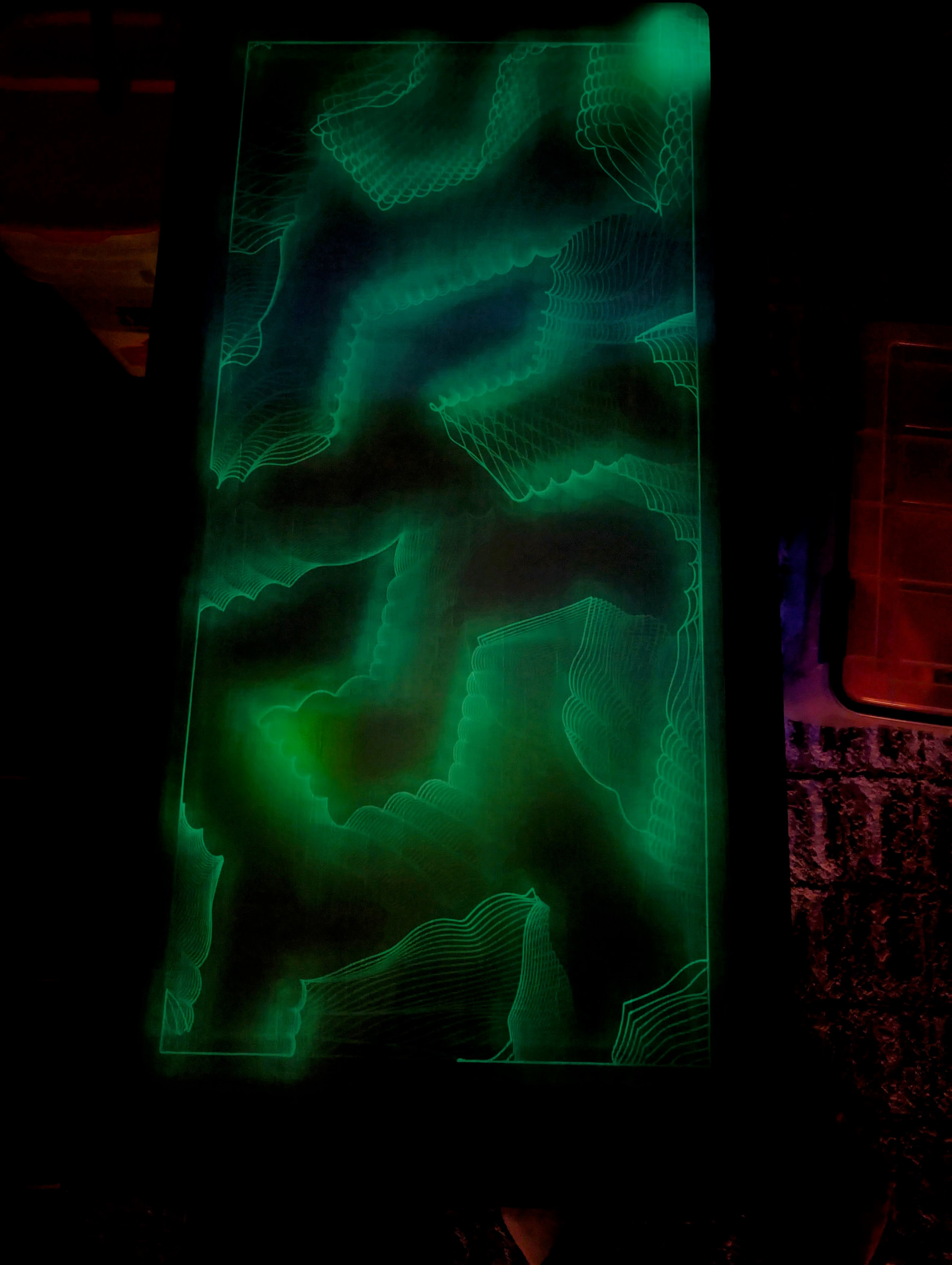
The sandbox is also made from 2040 v-slot with a white fake leather cloth covered 3/16” thick G10 fiberglass board fit into the lower slots, and LED strips fit into the upper slots. I painted a black frame on the underside of the glass top that just sits on top of the sandbox. The sandbox screws down onto four posts at the corners of the support frame. I added more LED strips (with a power switch) to the underside of the mechanism frame to light the floor with the same colors used on the top of the table.
The sides of the mechanism will be hidden by some 1/8” mirrored blue acrylic pieces that will fit into the slots in the 2020 t-slot support frame. I am planning to cut and install them tomorrow.
Thanks! I’ve been working on the design for a couple months. Actual construction is going pretty fast. I could probably duplicate it in a couple weeks, most of that waiting for ordered materials and parts to arrive.
All the printed parts are PETG. The magnet carriage has been through 3 or 4 design revisions and reprints. Initially I used some blue PETG and discovered that it was transparent to the optical endstops, so I switched to black. Then I had a problem with the belts coming out of the clamp, until I redesigned it so that the ends of the belts fold back on themselves.
The pulleys are printed so the F625 bearings press fit into them, and there’s a washer between the two halves to ensure that when the pulleys are mounted the pressure applied by the bolt doesn’t side load the bearings. Most of the pulleys are 23mm in diameter at the center, but there are a few that are 33 mm in diameter. I solvent welded the two halves of the pulleys by putting a drop of ethyl acetate (sold at home depot as “MEK substitute”) on the contact point. The pulleys are concave so most belt contact is on the edges of the belt. This may lead to rapid wear of the belts and/or pulleys. I’ll know in a few months.
I originally bought some wheeled carriage assemblies for the Y axis but found problems with the way they were made, so I ended up using the wheels and made my own plates for them from 1/8” aluminum. I bought a 520 mm linear guide for the X axis, and had to shorten it by a few mm on each end using a cutoff saw. The guide rail is mounted using only one M3 screw on each wheeled carriage. the screw passes through a 3mm slot so the rail can slide a little along its length in case the Y axis rails aren’t perfectly parallel. There’s a printed part the ends of the guide rail fit into that restricts rotation around the screw.
The strong magnet on the linear guide bearing block will cause the bearings in the block to tend to stick to each other and will attract ferrous particles from the environment to the rail, so I’ll have to check it periodically to make sure the rail is clean. I tried a 10mm ball initially and the magnet pulled on it so hard it lifted the magnet in the carrier. I have since wrapped it with gaffer’s tape and then put a zip tie around it and now it doesn’t lift up.
I am having shoulder surgery next week, so trying to finish up before then. There are just a few things left to do. I have to assemble and install one of the ReDump protection circuits, cut and install the acrylic side panels, and maybe neaten up the wiring a little.
Next week, when I have only one arm available, I’ll work on the software to scale the Arrakis 2.0 patterns to fit on Arrakis 3.0.
Is there any way to get access to older versions of sandify? It seems impossible to generate some types of patterns I was creating with one of the old versions.
Yes. The releases are all tagged. You will need to run the locally, using npm. I use docker, so I don’t have to clutter my local npm install. If you don’t have docker or npm installed, you can choose to run locally using either method.
v1.0.0 was the most dramatic change. So I would at least try before that.
You could also import the gcode directly as a new layer. You won’t be able to tweak the patterns. But if you just want to crop and scale, that should be way easier.
Thanks. I’ll see if I can figure out running the old version locally.
I tried importing one of my Arrakis 2.0 files to sandify. I set machine dimensions to the new table size- 465 x 1005. The imported pattern/layer goes in a bit strangely. When I specify the X and Y sizes, Y is exact- I specify the new table size as 1005 and the pattern scales to 1005. But the X axis doesn’t work that way. In order to fill the drawing space that is 465 mm wide, I have to set the X dimension to 768. Import also strips off my dual speed edits, so I have to run my dual speed post processor again to get dual speed on the newly scaled pattern. I can live with that. Once I get the X scaling set it seems to work fine.
Maybe there’s a bug in the import code that causes X to scale differently than Y.
a few minutes later…
Further testing shows the X scaling behaves differently depending on which dimension you set first with the aspect ratio lock turned off.
Further testing finds that there is a file size limitation. Some of my larger pattern files crash the sandify program.
I realized that instead of screwing the sandbox down onto the posts in the blue support frame, all I had to do was put threaded pins in the posts and drop the sandbox onto them. The sandbox already has the holes and the posts are already threaded. Pins are on the way.
I added mirrored blue acrylic side panels with some clear silicone edging material to center it in the slots and prevent it from rattling. I think it turned out well.
This is the electronics plate with everything mounted. I did my best to neaten up the wiring with zip ties. The connector between the motors is for the LED strips in the sandbox. If I want to take the sandbox off, I just remove the glass, disconnect the LED strips, and lift the box off the support frame. If I want to do some work on the mechanism, I can just lift it out of the support frame.
I have to make some guesses on what you want when you import a pattern. If it was text, you wouldn’t want it stretched. If you want it to fill a new table size, you might want it stretched. So you have to do the scaling pretty manually.
That makes sense too. Sandify does not know about most gcode. So when it sees anything other than what it does know, it drops it. And it knows very little.
That makes sense. When I get the scaling program working I’ll post a link here in case anyone else might have a use for it.
The final parts for the table will arrive today - the pins to locate the sandbox on the support frame (currently using Allen wrenches!), and the line cord. I went with a clear jacket 18 gauge lamp cord as Ms. Kitty is unlikely to chew on it. I taped a large piece of cardboard to the underside of Arrakis 2.0 to keep her from chewing on the belts. She has shown some pathological interest in the belts in this table, too, so I may have to add a sheet of cardboard.
I have noticed one potential problem- when sitting idle with LEDs on, the power supply cooling fan kicks on sometimes. I’m thinking there’s a problem with the temperature monitor in the power supply, so I might have to replace it.
I have written a scaling program in Perl that can take drawing files made for one size rectangular table and scale them to fit another size table. I’m running some tests to verify and will post a link if it works reliably. I have written it to read FXXXX speed specifiers that I use on each G1 line in dual speed drawing files and write them to the output file so I don’t have to rerun the dual speed program on the scaled files. I’ll have to test it on single speed drawing files (without the FXXXX speed specifiers on every G1 line) to see what happens. The program requires only the name of the file to be scaled and the new maximum X and Y values. It extracts the old maximum X and Y values from the input file and calculates scaling factors for X and Y to use for the output file.
I have run into two issues with Arrakis 3.0. First, the cheesy power switch I used has had it’s contacts welded shut by power-on surge current, so the table is permanently ‘on’. I’ll be replacing it with a proper switch shortly. Also, the glass seems to be too close to the sand. When I run the table at high speeds the ball kicks up the sand and some of it ends up stuck to the glass. That means I have to clean the glass more often than I prefer. I could just run the table slower, but that’s no fun, so I’m going to make a new sandbox using 2060 t-slot instead of the 2040 material it uses now. That will raise the glass from 28mm to 48mm above the sand and should solve the problem.
But what to do with the old 2040 sandbox frame… I have an idea for that. When I’ve tested it I’ll post about it. It turns out the way I designed and built Arrakis 3.0, with locator pins that center the sandbox on the support frame, makes it very handy for experimenting!
I got the scaling software to work and scaled 200+ drawings that were made for Arrakis 2.0 to fit Arrakis 3.0. I ran into a couple issues. The biggest was that at some point in 2022 sandify was updated and G01 statements were replaced by G1 statements. I had to modify my software on the fly to accommodate whichever type G statement was in the drawing file. When my program writes the new output file it write G1 statements regardless of whether the original file had G1 or G01 statements. It also reads the F speed specifiers in each G1 line and copies them to the output file, so my dual speed files (produced by my dual speed post processor) scale without any further messing around.
The other thing I discovered was that a few of my drawings didn’t use the entire space available on the table. My scaling software searches for the maximum X and Y values in the drawing file and uses them to compute scaling factors based on the full dimensions of the new table. That means a drawing that didn’t hit the maximum Y value will get stretched until it does hit the maximum Y value on the new table. It’s not a big deal but it threw me for a minute when I saw the scaling factors come up with values I wasn’t expecting.
I’m sure there’s some relatively easy way to make the software accept either G1 or G01 statements, but my current need is finished, so I probably won’t mess with it further until I build another table. Since the scaling I did today all contains G1 statements, I really won’t need to modify the program for the G01 statements again.
Update: For some reason, the power supply fan in the table turns on at random intervals for a few minutes at a time, even when the motors aren’t running. I don’t like to hear the fan, so I am going to replace the one LRS-350-24 power supply with two fanless LRS-200-24 supplies.
The power switch I used, supposedly rated for 8A, welded its contacts in the ‘on’ position about the 3rd time I used it. The power supply specs say inrush can be as high as 60A! I have ordered some NTC inrush limiters to install, along with a new power switch.
The LEDs are powered from the 24V supply in the table. I have decided that isn’t ideal because I’d like to be able to stop the table from erasing a drawing and leave the LEDs on, so I’m going to install a separate AC powered supply for the LEDs with its own power switch. That way the table can run in the random sequence mode and if I see a drawing I’d like to leave on the table for a while I can switch off power to the controller board and leave the LEDs lit. Or if I’m watching TV in a darkened room, I can switch off the LEDs whether the table is running or not.
I found that a comb does a nice job of spreading the sand after the table has run for a while and pushed the sand toward the edges of the drawing area. I got myself a new printer for Xmas and decided to test it’s multicolor capabilities by printing a comb for Arrakis 3.0.