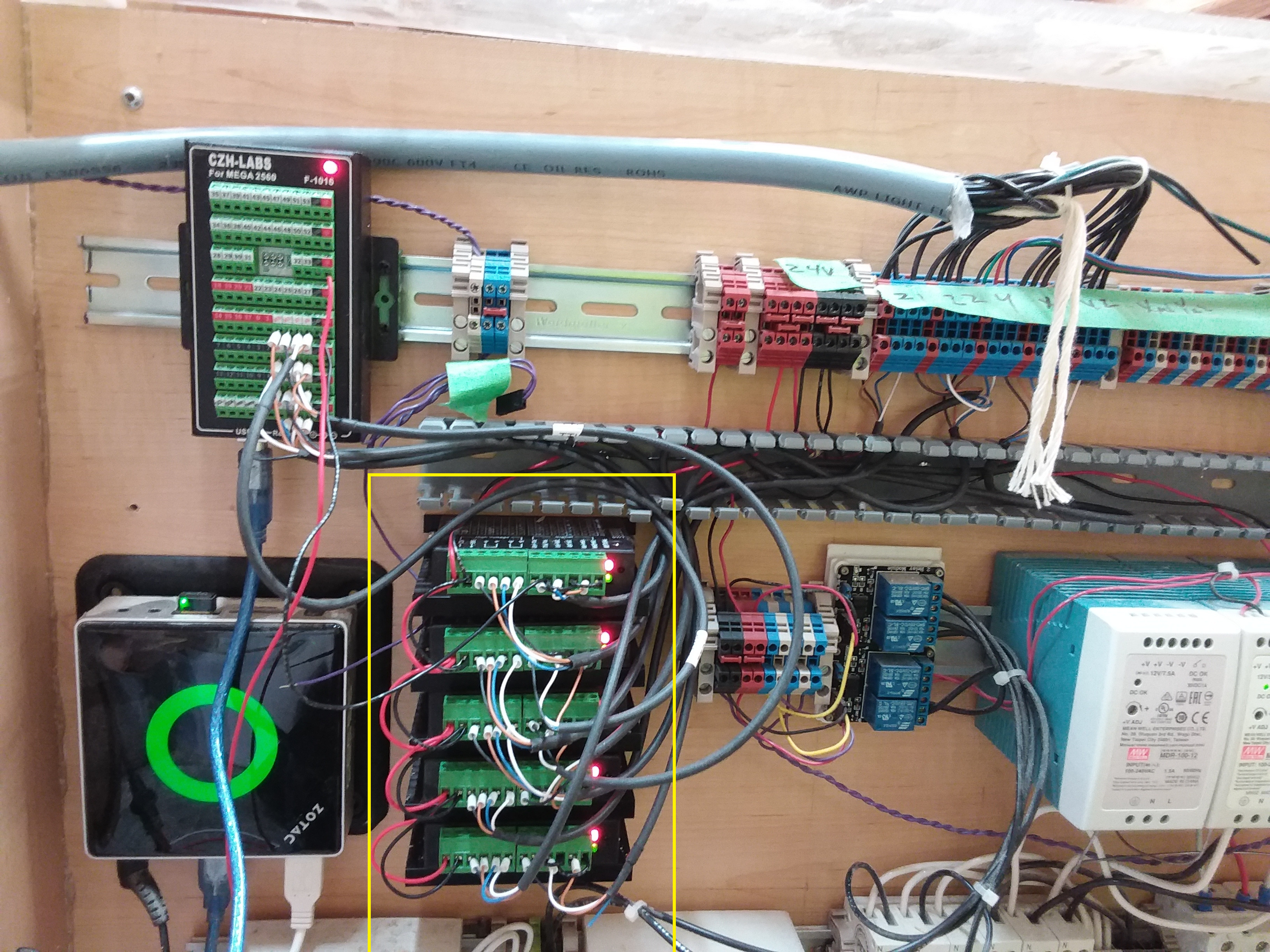
I am trying to convert from a RAMPS setup to independent TB6600 drivers as shown.
The main reasons for doing so are to get rid of messy wiring and tiny connectors, to ensure adequete cooling when I drive my motors hard, and to be able to consider NEMA 23 motors in the future.
The wiring of these drivers is dead simple.
- Power for the motors (I`m using 24V)
- Connection to motor coils.
- Connections to 5V STEP, DIRECTION, and ENABLE.
Yet what I am finding is that no power is getting sent to the motors.
This is what I have tried:
- Confirmed EN is LOW (inverted)
- Confirmed that DIR changes between 5V and 0V when I move the controls back and forth.
- Confirmed with my scope that pulses are getting sent on the STEP line.
- Confirmed low impedance across each pair of coil windings.
- Confirmed 5V where there should be 5V and 24V where there should be 24V, each with their own grounds.
- Microstepping is set to 32.
- Tried a few different current levels.
- Checked voltage at coils. 0 VDC, and 15 mVAC.
- Plotted coils on scope, no changes when there should be motion.
- Measured current to coil. 0A.
- Powering only one in case I was overloading my power supply.
I have 5 drivers, so obviously I`ve checked more than one.
Each driver has two LEDs labelled POWER and FAULT. One is red and one is green, but it is not clear which is which. The red LEDs are always on. The green LEDs are usually on, but seem to go out briefly if I am applying pulses. My understanding from reading the docs of a similar model is that if there is fault (e.g. overvoltage, overcurrent) that it is encoded in a certain number of flashes; so I don`t think I have a fault condition.
Thanks in advance.