All,
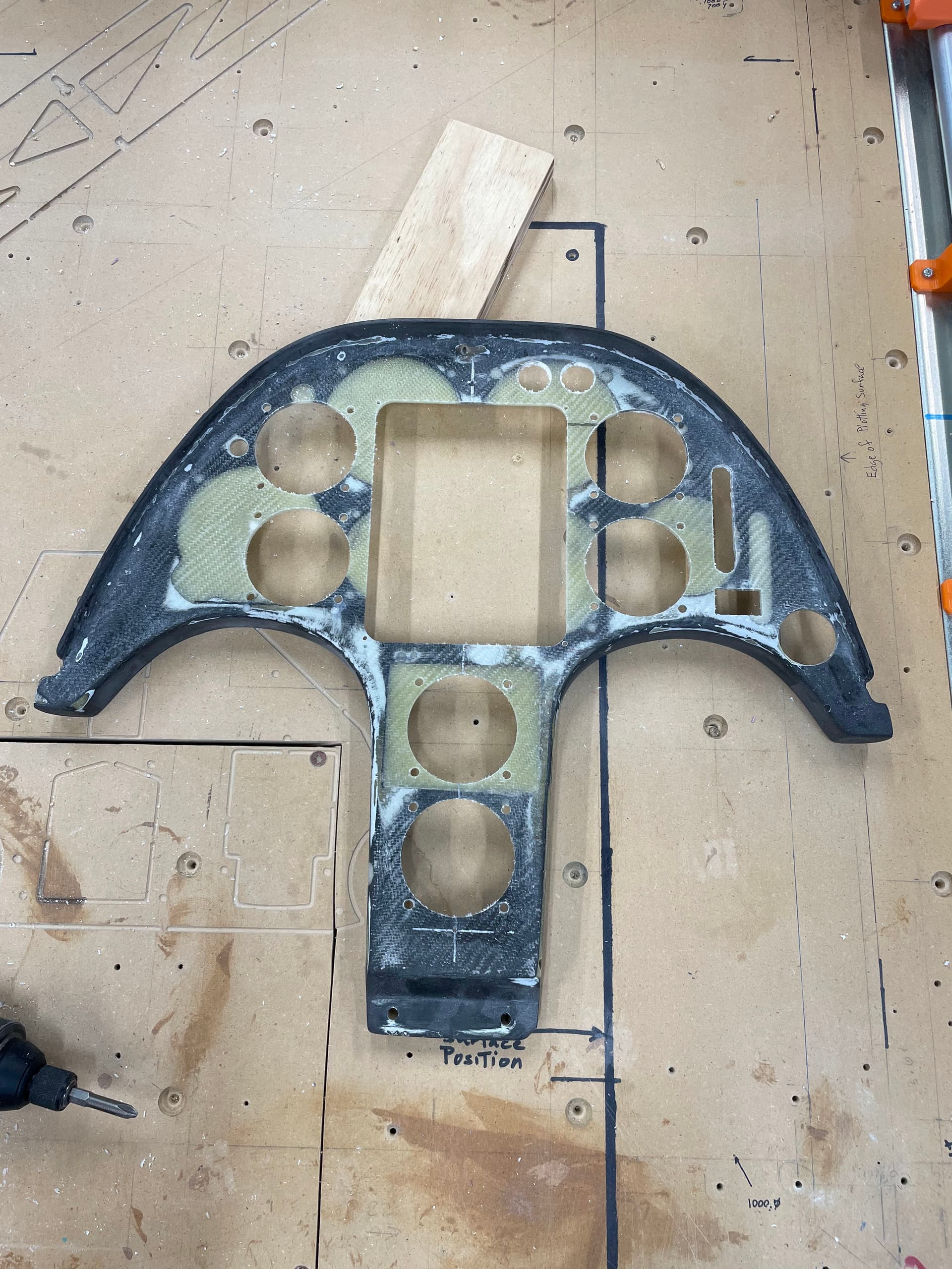
Here is the latest instrument panel cut on the Lowrider 3:
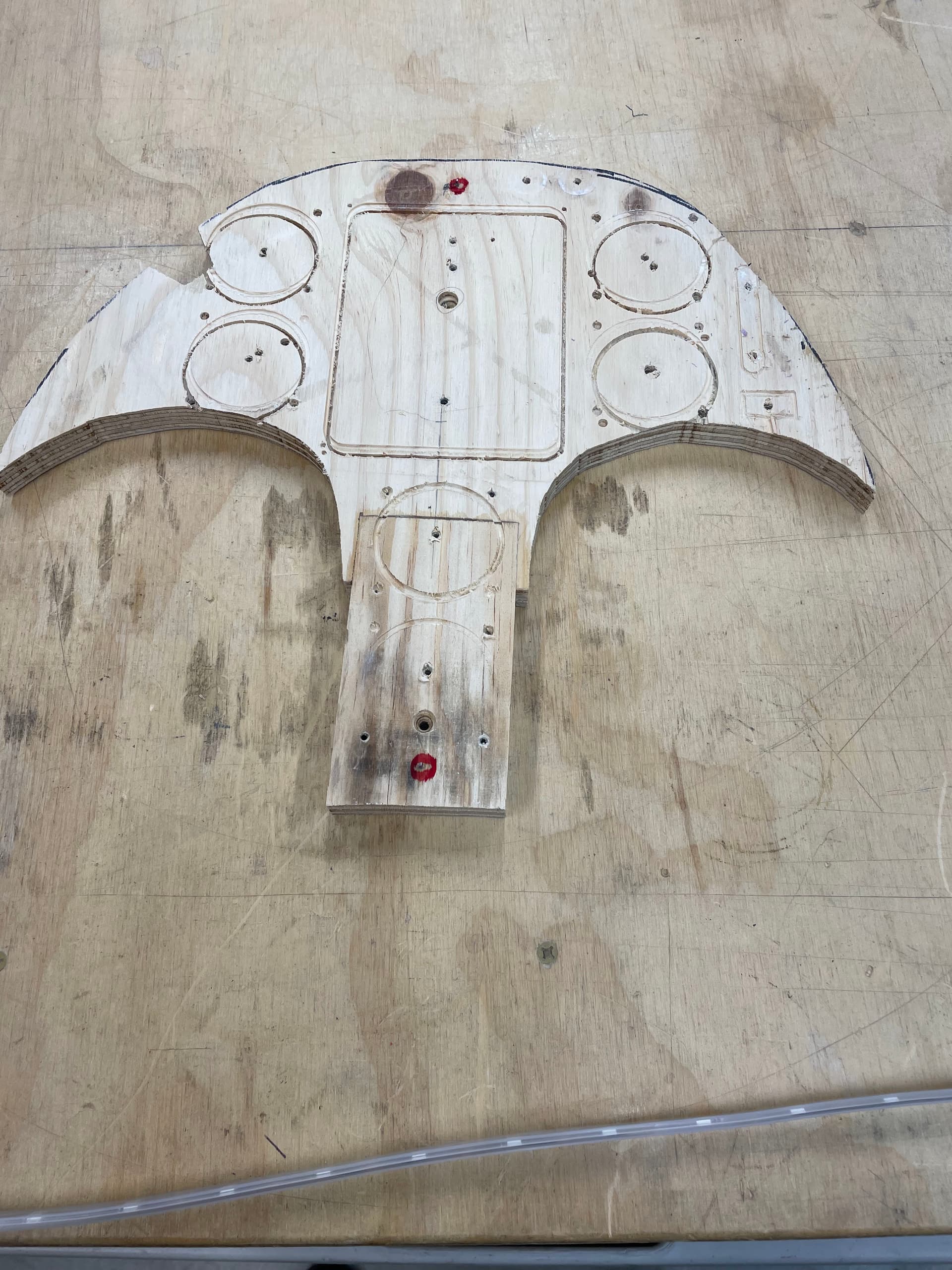
You can see all the previous holes that had to be filled before cutting holes for the new instruments. The light colored areas are the filler pieces I cut from a laminate panel I layed up first. Those pieces were also cut with the Lowrider. I then glassed the front and back to “seal” in the filler pieces; the panel thickness was 3mm after all that.
I used a drawing from the factory to plan the instrument arrangement, BUT, this glider is serial number 3 of the series. Number 1 is the prototype, number 2 was used for certification, and this one was the first production model. I’m sure you can see what’s coming ![]() . The factory drawing includes changes as the series reached full production. This panel didn’t match the current factory drawing.
. The factory drawing includes changes as the series reached full production. This panel didn’t match the current factory drawing.
My first gcode was just for the instrument mounting holes and during the cutting of the 5th hole it cut right at the edge of the panel. Emergency STOP! (Prior Lesson: start with small cuts that can more easily be fixed.)
Take it off the fixture, (Fortunately I did make a fixture with keying pins. That really saved this project). Fill the bad holes and start measuring.
I laid out a center line and measured every dimension off that line. Taller in some places, shorter in others than the factory. Remember, last year I started a thread about wanting to photographically scan a part?
After getting an accurate drawing, the rest was pretty easy, except for the two(!) broken mills. (Ask me later, it’s still a bit painful)
Anyway, another saga in panel making. It ships first thing Monday morning.
Mike