I was using an inch tape as I didn’t have a metric tape. I was converting the inch values to metric at the rate of 25.4 mm per inch. After all the remeasuring, with more and more attention to the process, I am convinced the error is within the limits of my ability to measure it.
In the quote you made above. I moved the machine 800mm and expected to measure the distance with the inch tape as 31.469. I actually measured 31.468 (fractional measurements converted to decimal) and as that is within less that .5mm over 800mm. I’m happy.
The fact that I can’t measure any any more accurately across that distance, means (to me) that I’ve got pretty accurate movement on the machine.
I’ll get the strut plates cut and mounted before I do anymore attempts to measure any of it.
Thanks for chiming in, I’m likely to need all kinds of help on this larger build. I did just fine on the Primo, but this one seems much harder to me.
I just measured the diagonals of a 1000x800mm rectangle, the difference is 0.0006% of the distance!! Diagonals were 50.3125 and 50.3437. Just a little less than 1/32 of an inch.
So I’d call it square!
Thanks again for all your help, time to cut strut plates!
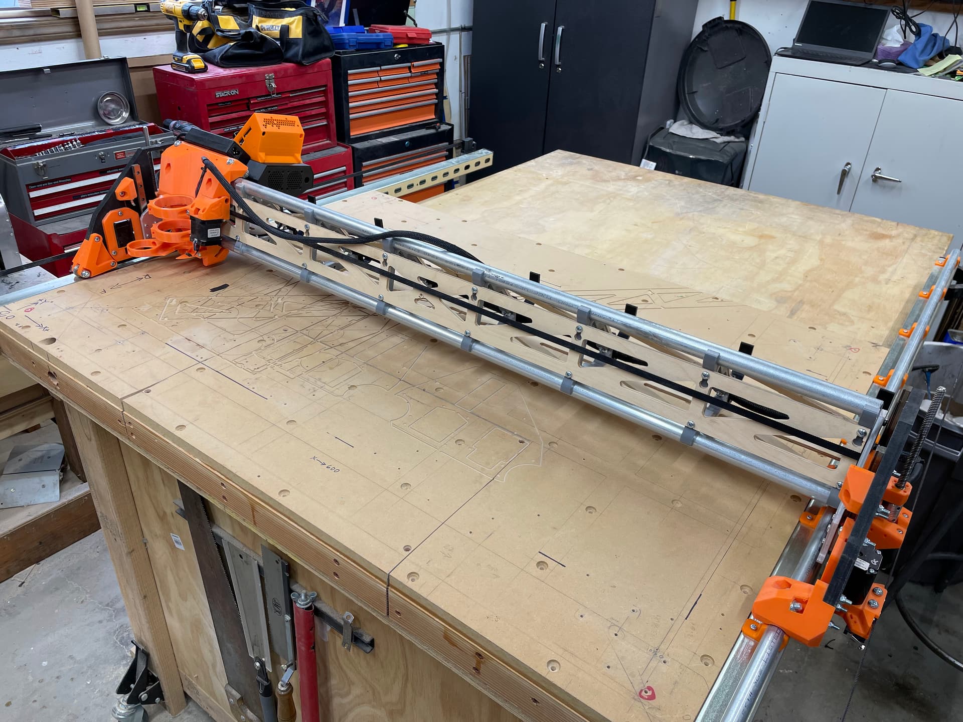
My Z2 endstop switch seems to not be read by the controller after the machine warms up (been running for 20-30 minutes). After I first turn it on I can home Z with no problems, but after a few cycles of homing the Z2 stepper continues to drive the axis up even after the switch clicks, and the LED on the board lights up. I rebuilt the whole Z axis endstop pair with new switches and still see this problem after a few minutes. I know there is a similar problem being seen on other SKR Pro 1.2 boards. I’d rather not remove the LED. Can someone point me to the right resistor value and location on the board (picture please).
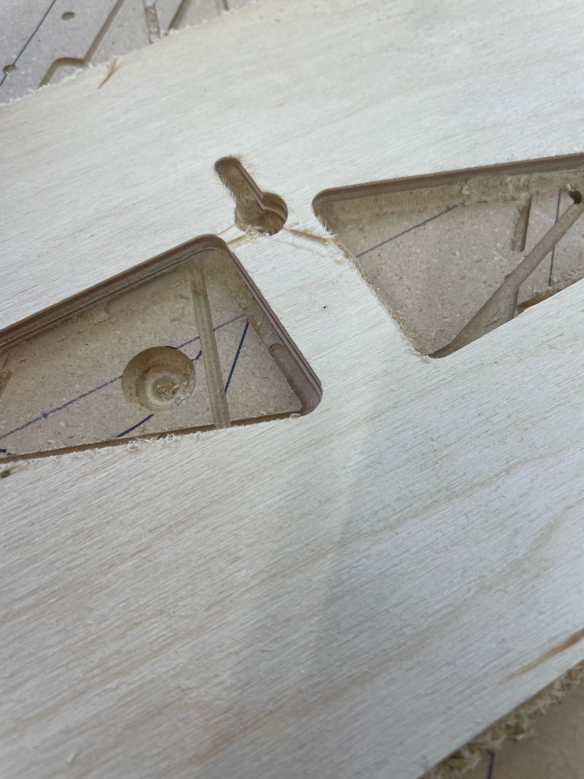
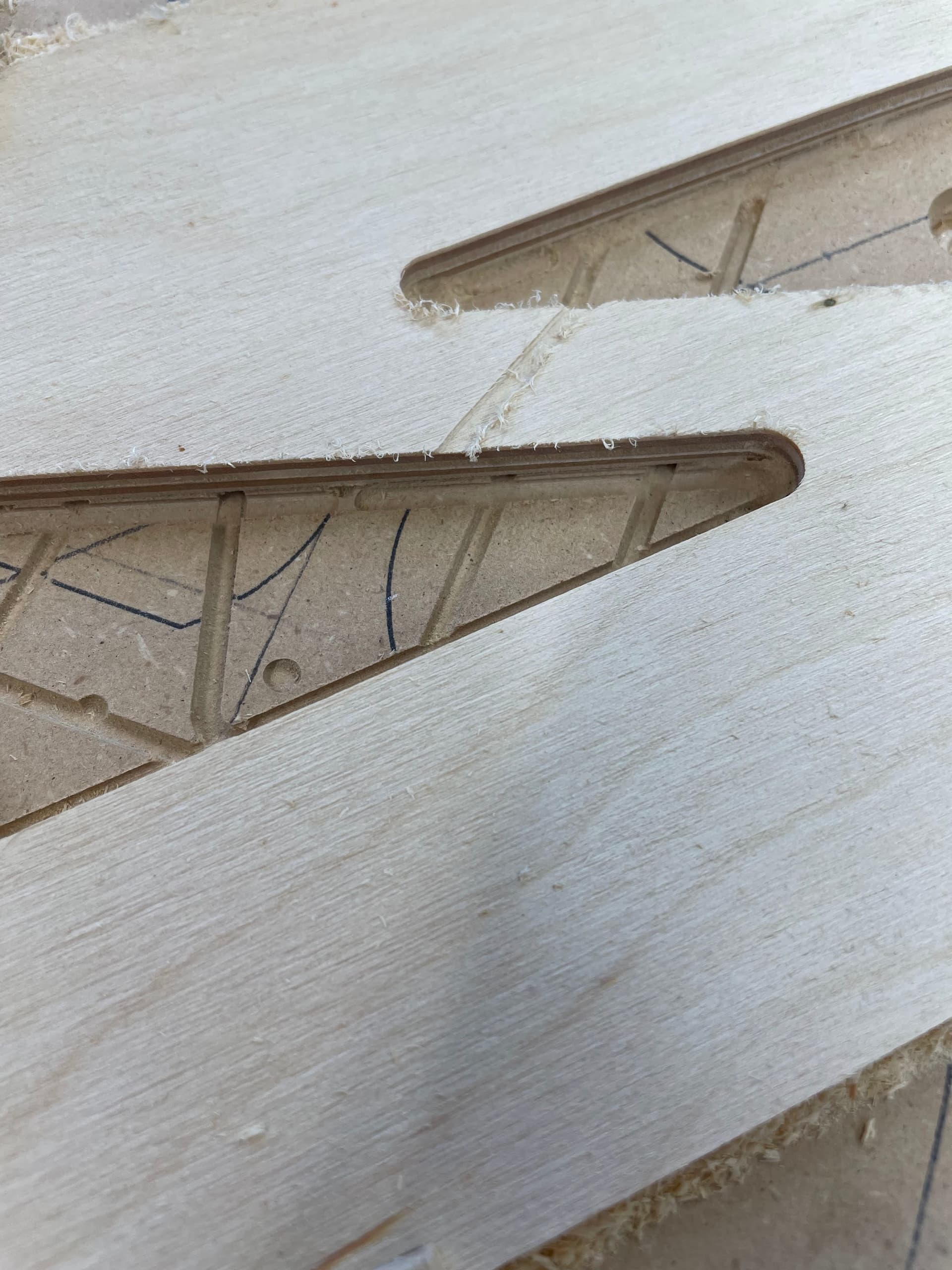
When I thought everything was ok with the Z homing, I started to make my strut plates. After the 3rd or fourth cutout, the bit started dragging in the workpiece.
I stopped the cut, rehomed the machine, and reset the workpiece origin. I checked that the bit was tight in the collet, but just to be sure I loosened and retightened the bit then reset the Z origin. When I reran the job it dragged again after the second cut, just not as deep.
Maybe the Z is losing steps? That is the only thing that comes to mind when the bit is tight in the collet.
Or, bear with me, the grub screws of Z are loose.
Feed rate for the Z is 3mm/sec, rapid-Z is 480 as noted in the DOCs.
Grub screws are well secured (or were, see below).
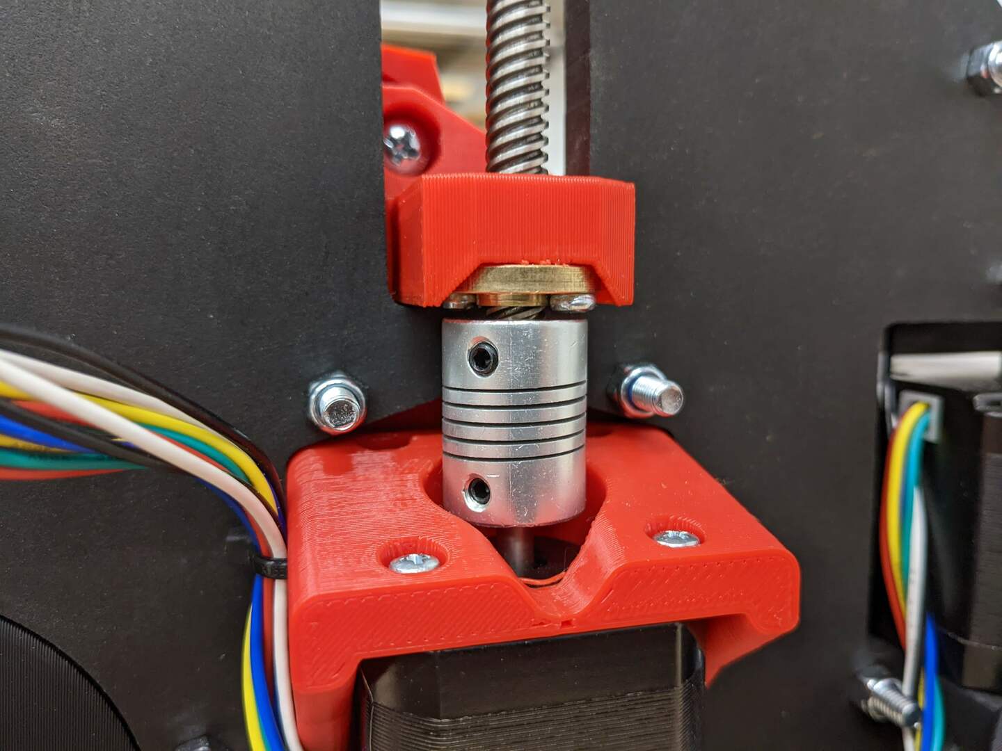
I took a good look at the stepper-drive screw coupler and noticed that they were both compressed, one more than the other, which allowed some vertical movement (but the grub screws were TIGHT). I removed the couplers and will remove all potential for inadvertent vertical motion.
I double checked the DOCs for the installation of the Z axis coupler and noted on this picture that there is no compression.
The couplers should be a bit expanded so they are always pulling the screw into the stepper shaft. at the bottom the brass nut should not touch the coupler.
I just finished doing that to the couplers. I was surprised that the coupler was quite a bit down the stepper shaft, and the drive screw was inserted just about 3/8 of an inch.
The first Z homing went fine, and there is no chance of the brass nut hitting the coupler.
Matt,
I have it set at 1mm (down from 3mm) but the surface is very flat, and I don’t think that is the problem, BUT I’ll raise it back to 2mm, for the next cut.
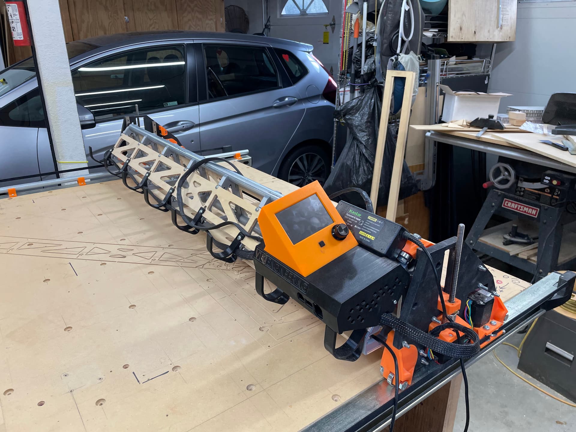
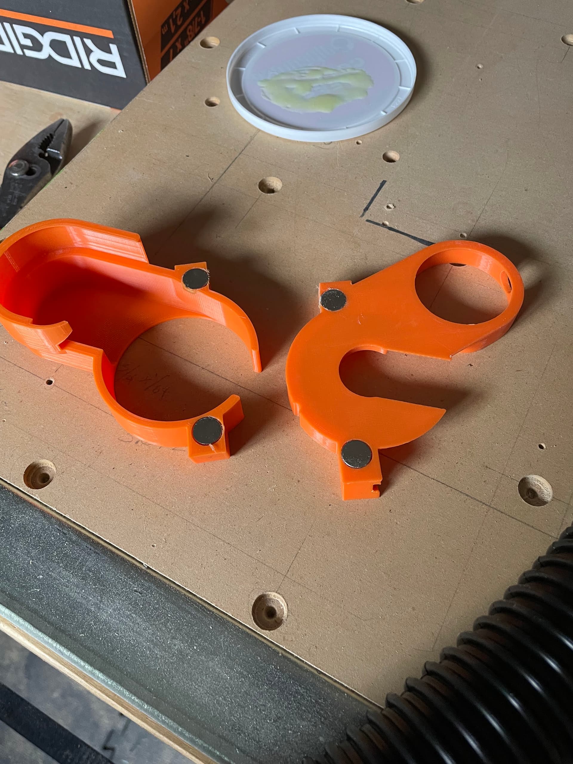
The strut braces are cut, but I didn’t put any finish on them. I was going back to the mantra of my R/C flying days “If it can fly, it’s done!”. I added some magnets to the vacuum hose retainer and shield. Pictures below, I just need to mount the hose and run the power.
I should have used smaller magnets, these 4 are BEASTS.
BTW, I just went and looked at both Printables and Thingiverse and the hose parts are not listed on either one. Did I get theses from some other location? I see them on Ryan’s machine.
Sorry I was looking at the list in the DOCs, and just missed the tool mount note. I, of course, did get the tool mount with the dust shoe. I must have read it correctly when I looked at it months ago.