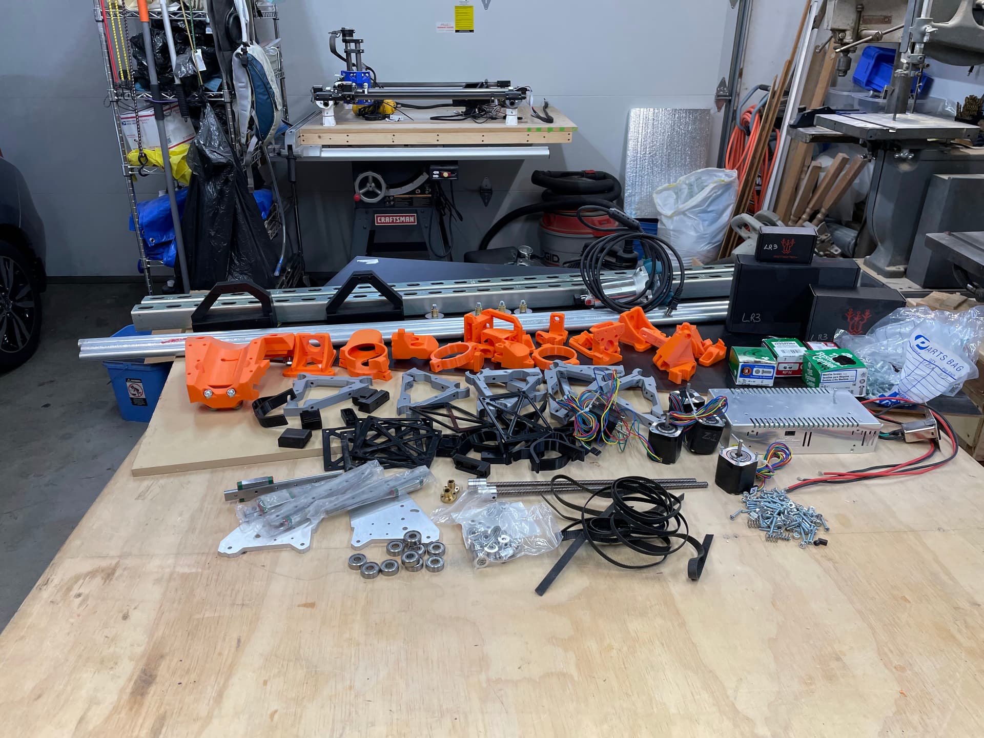
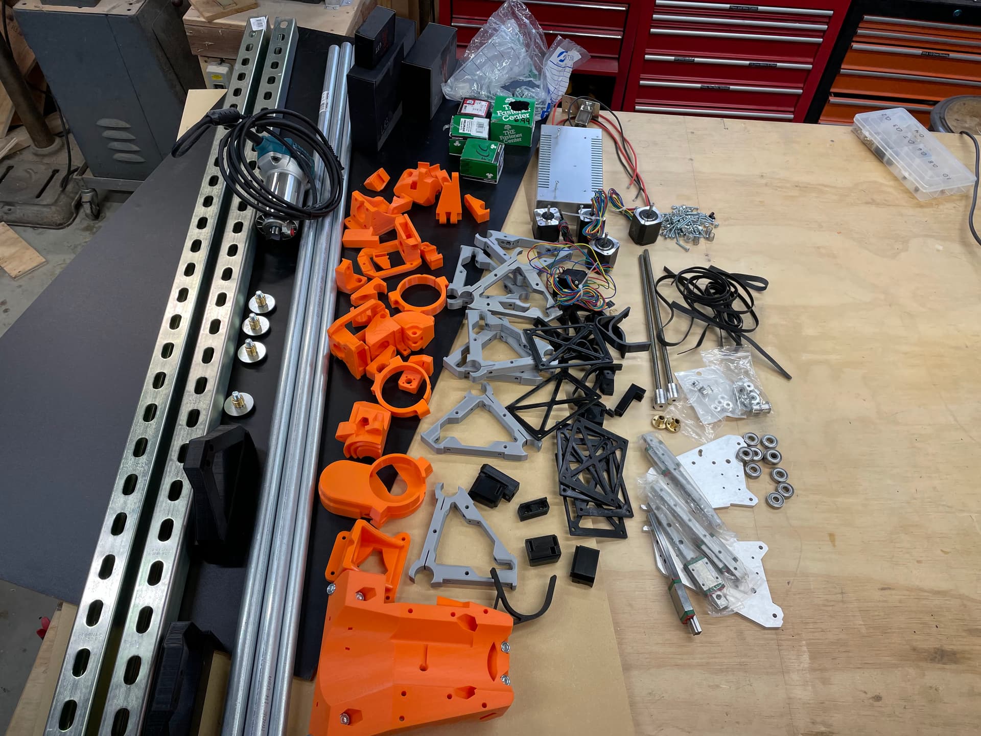
I’ve been printing and collecting bits for the last 3 months. Everything except the YZ plates and the struct braces are done. The plates are on the agenda for today, and the braces will wait for the build to get to the appropriate assembly stage.
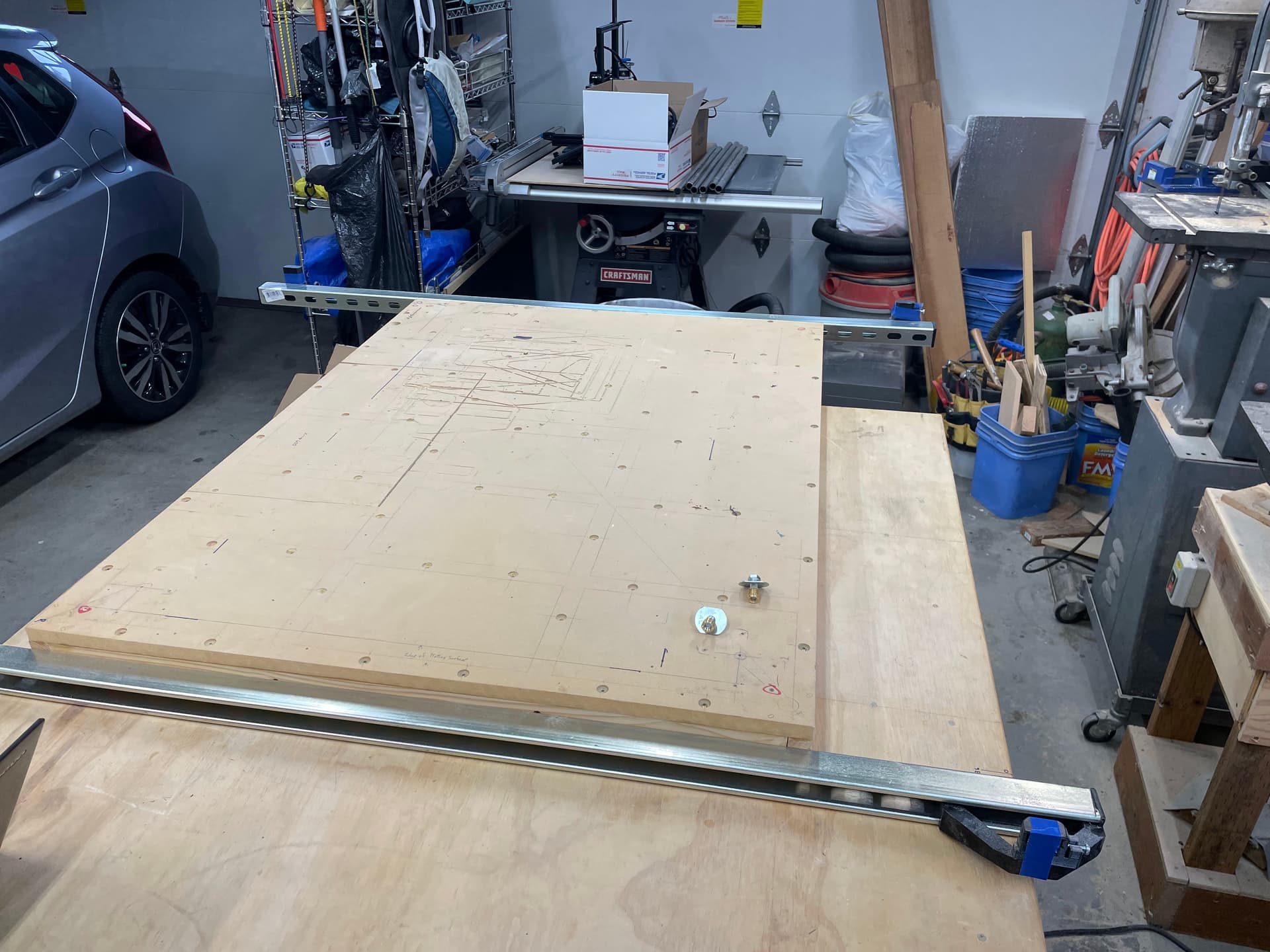
Took the Primo apart and will repurpose it for a smaller area of operation. I’m reusing the torsion box for the LowRider 3 build, so it had to be removed in any case.
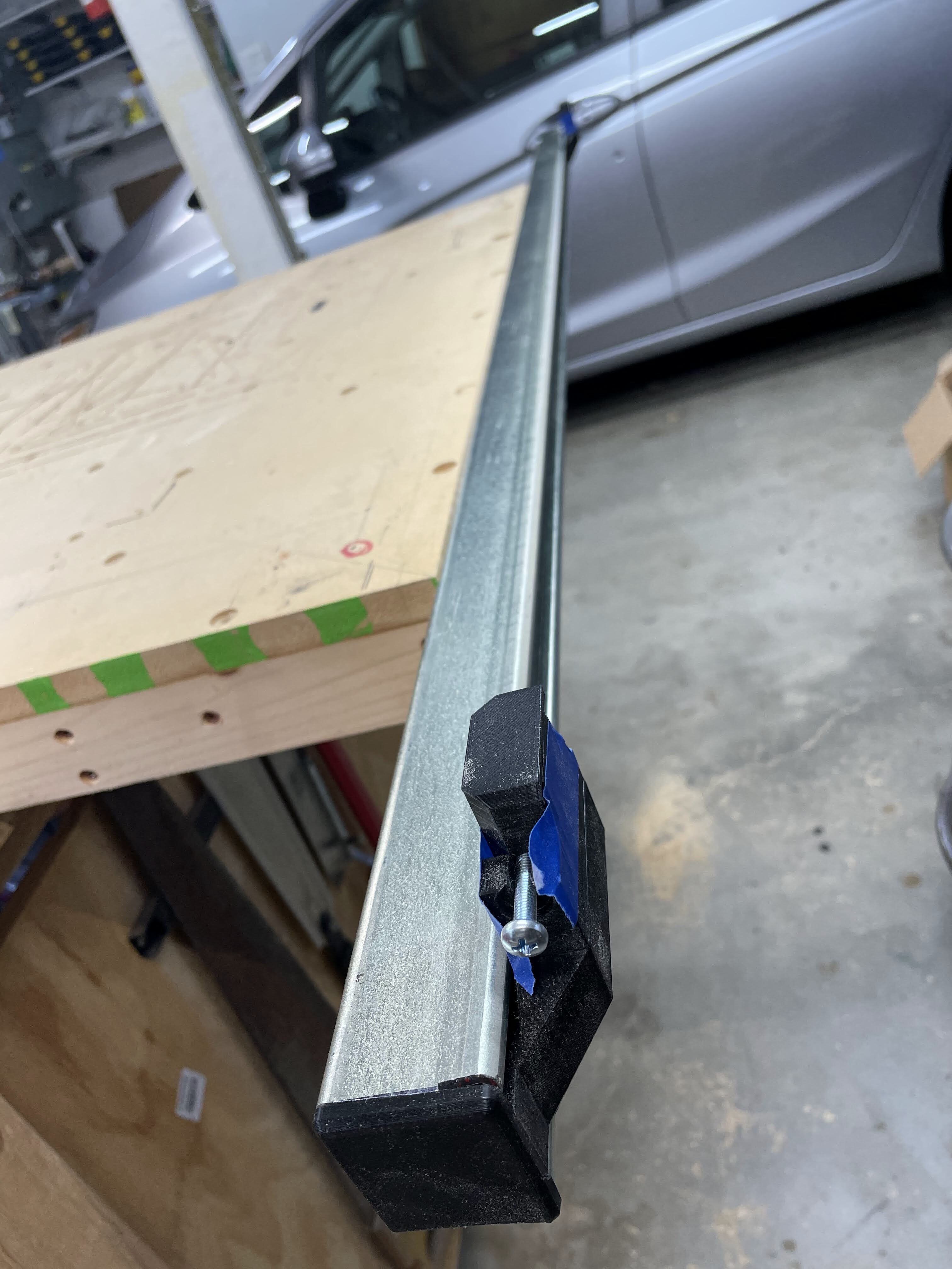
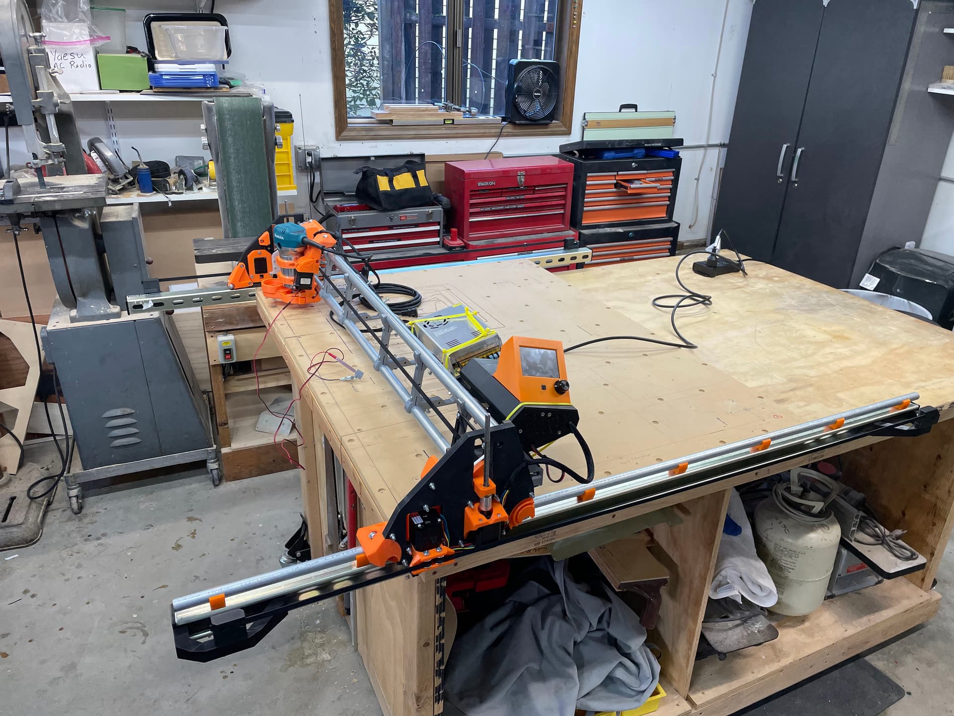
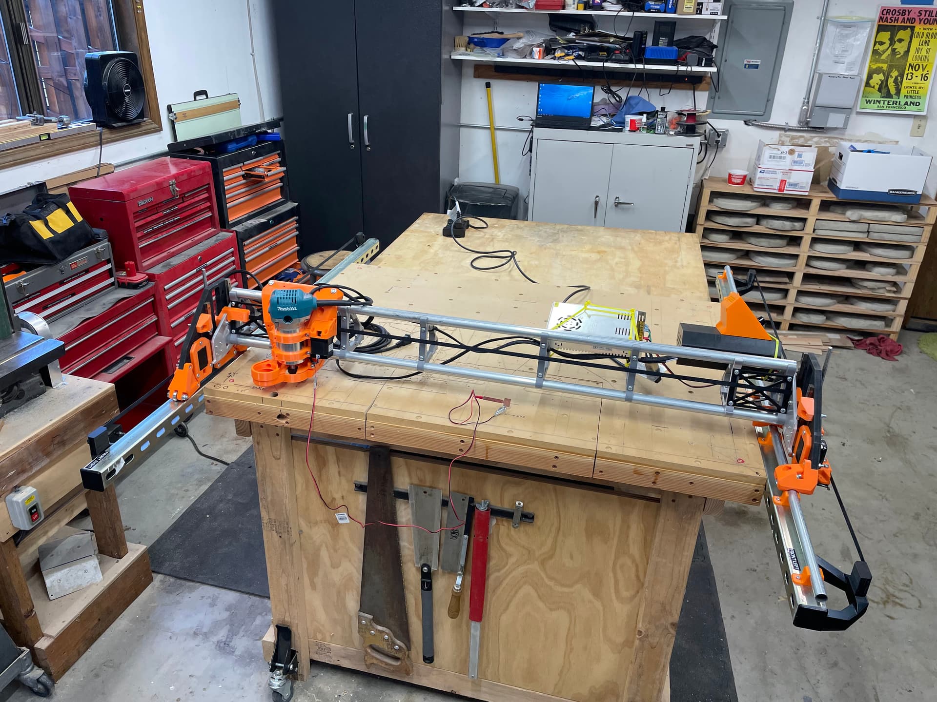
Using Doug’s uni-strut extension prints I have now struts positioned along the short side of my box. This should allow me to have an X cutting dimension of 48 inches. The struts are removable/ reposition-able to allow a cut on an overhung panel, without making a drop table. I addition, I can move the machine 0,0 point forward or back, depending on the overhang I need.
Glad the extension prints worked for you! They are working great for me. I suppose it’s possible that not all brands competing with “unistrut” make their products exactly the same, although hopefully they follow an accepted standard thickness and plan for size/shape.
Most progress has stopped, due to the need to reprint the Y rail mounting block. I had printed the “standard” blocks, but since I’m using the Unistruct rails system Doug designed, I’ve needed to re-print the correct blocks.
Would anyone like a set of Y rail blocks? I’ll send them anywhere in the US free of charge, Merry Christmas.
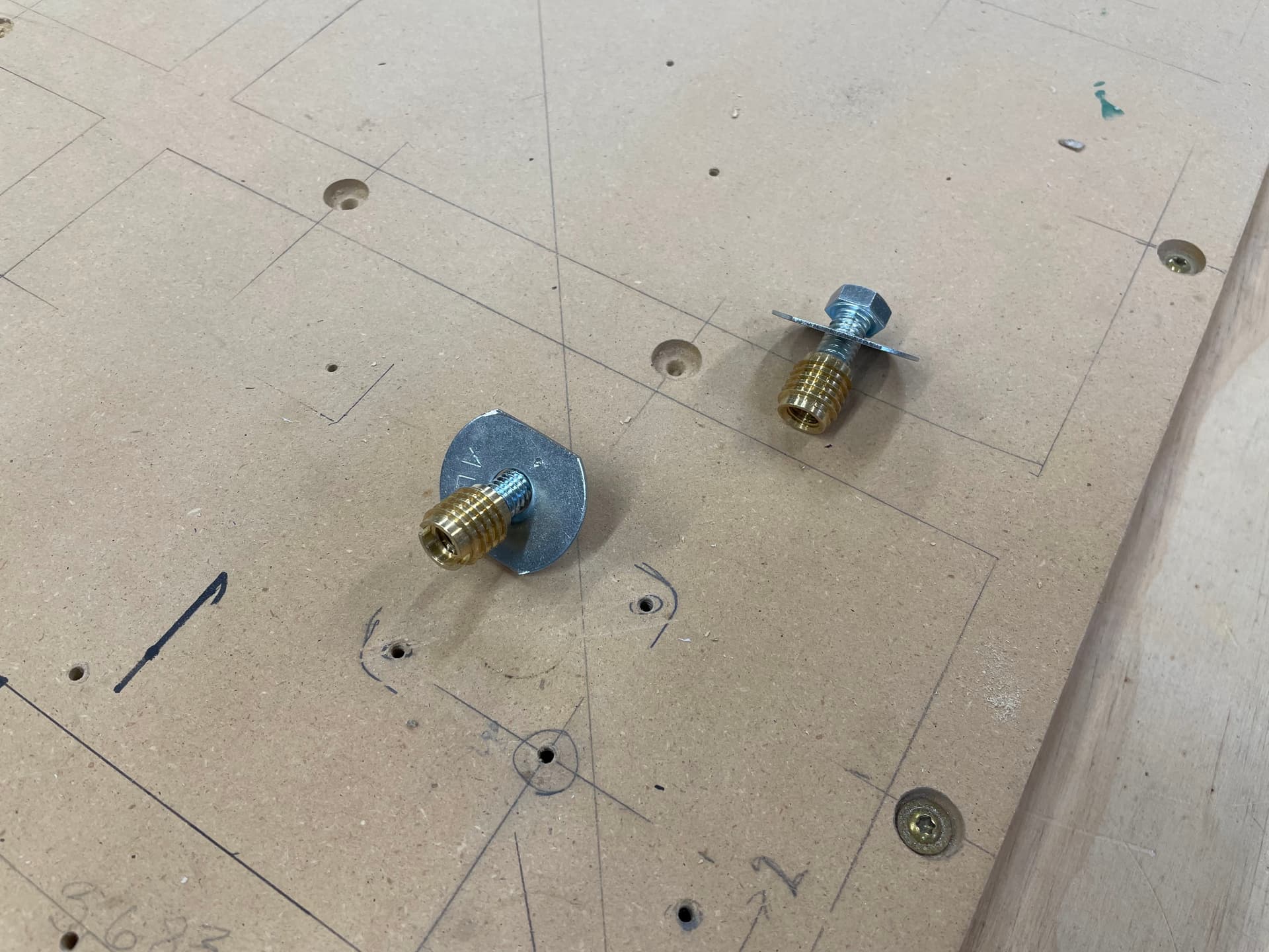
Those standard rail blocks can work, but they would simply push your EMT rail out in the air a little bit away from your unistrut. My custom remix moves the rail more over the unistrut.
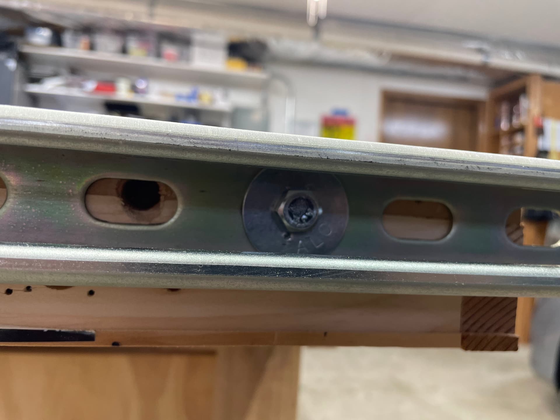
The Unistrut is drilled and tapped, the Y-rail mounts are printed, but given the festivities this weekend, I’ll not get much time to make any progress until Monday.
I’m almost through with creating Christmas gifts for family, and I’ve been trying to squeeze in time for more soldering on the aviation connectors on my LR3 CNC plasma control box. My goodness it’s a lot of connections for soldering.
I expect most of you in the USA have been dealing with cold, snowy weather, In addition I have been through one of the strongest wind storms I can remember. Wind storms, downed trees, loss of power, etc.
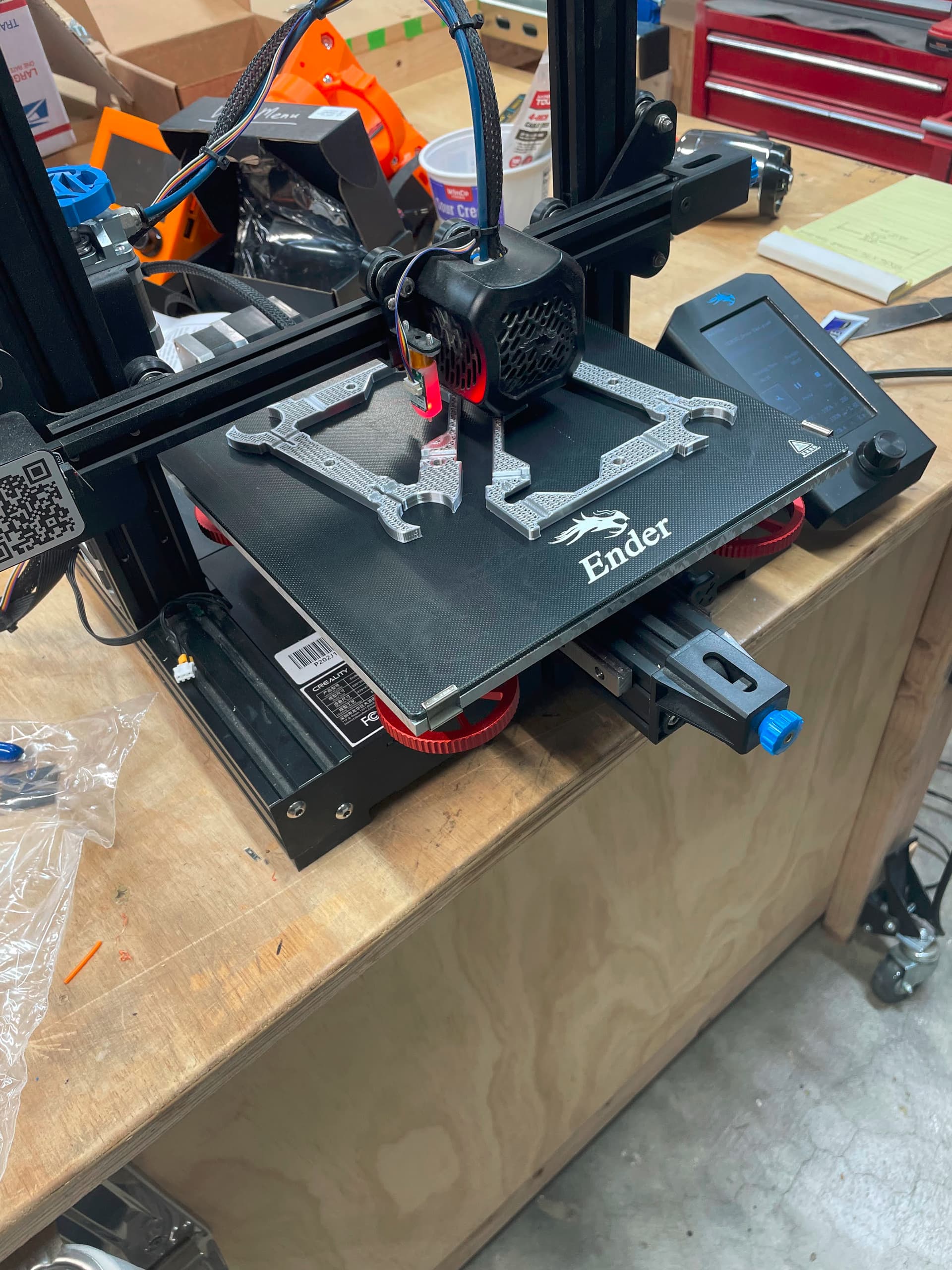
Right in the middle of a print I just had to have.
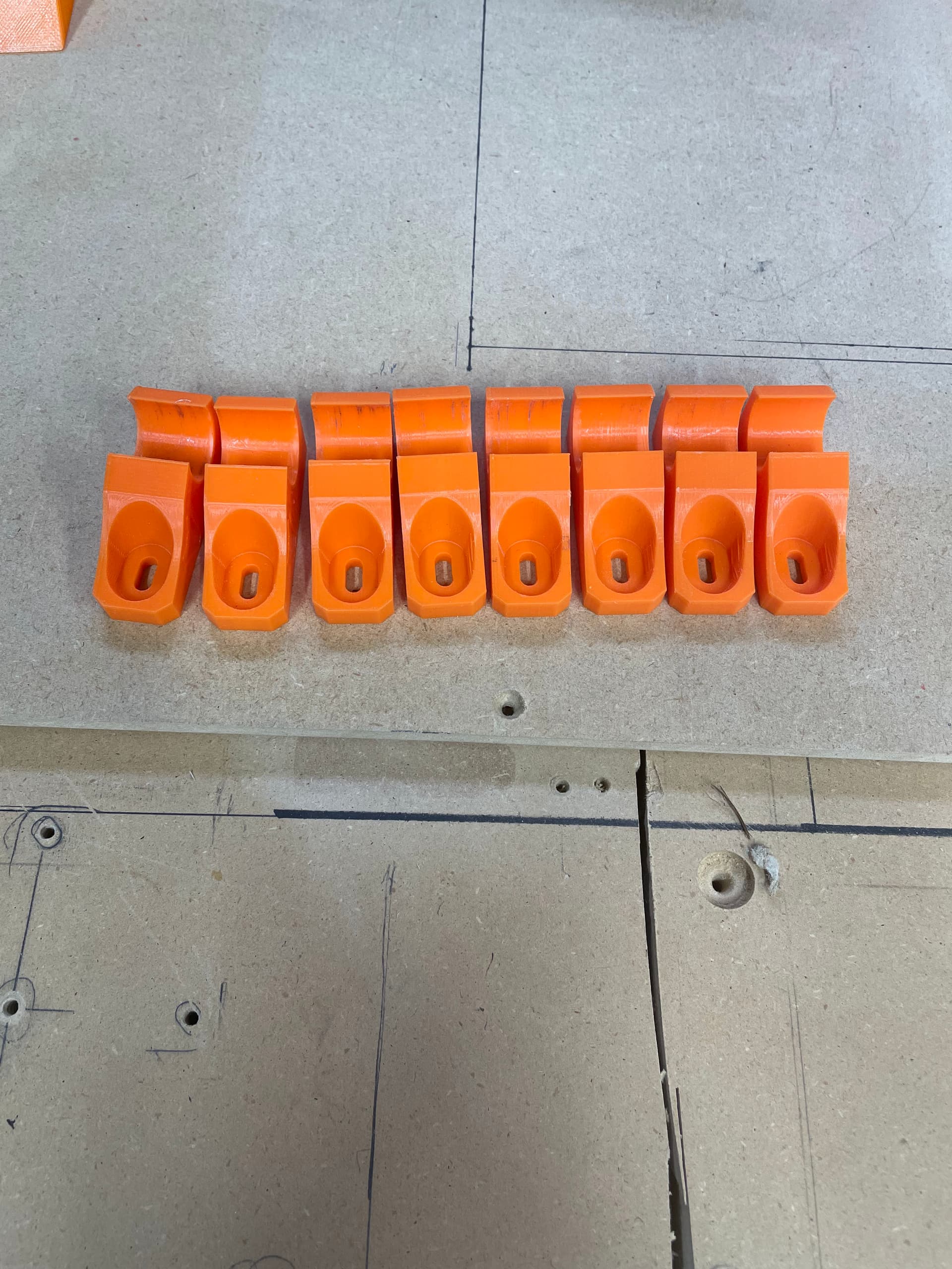
Originally I printed only 7 Braces, but needed 8(!), so I decided to print a spare while I was doing it. The power when out shortly after the above picture was taken. The power cam back on 15 hours later and I started another print only to have the power “flicker” for a moment crashing the second print! The third times the charm, and I was able to start assembly.
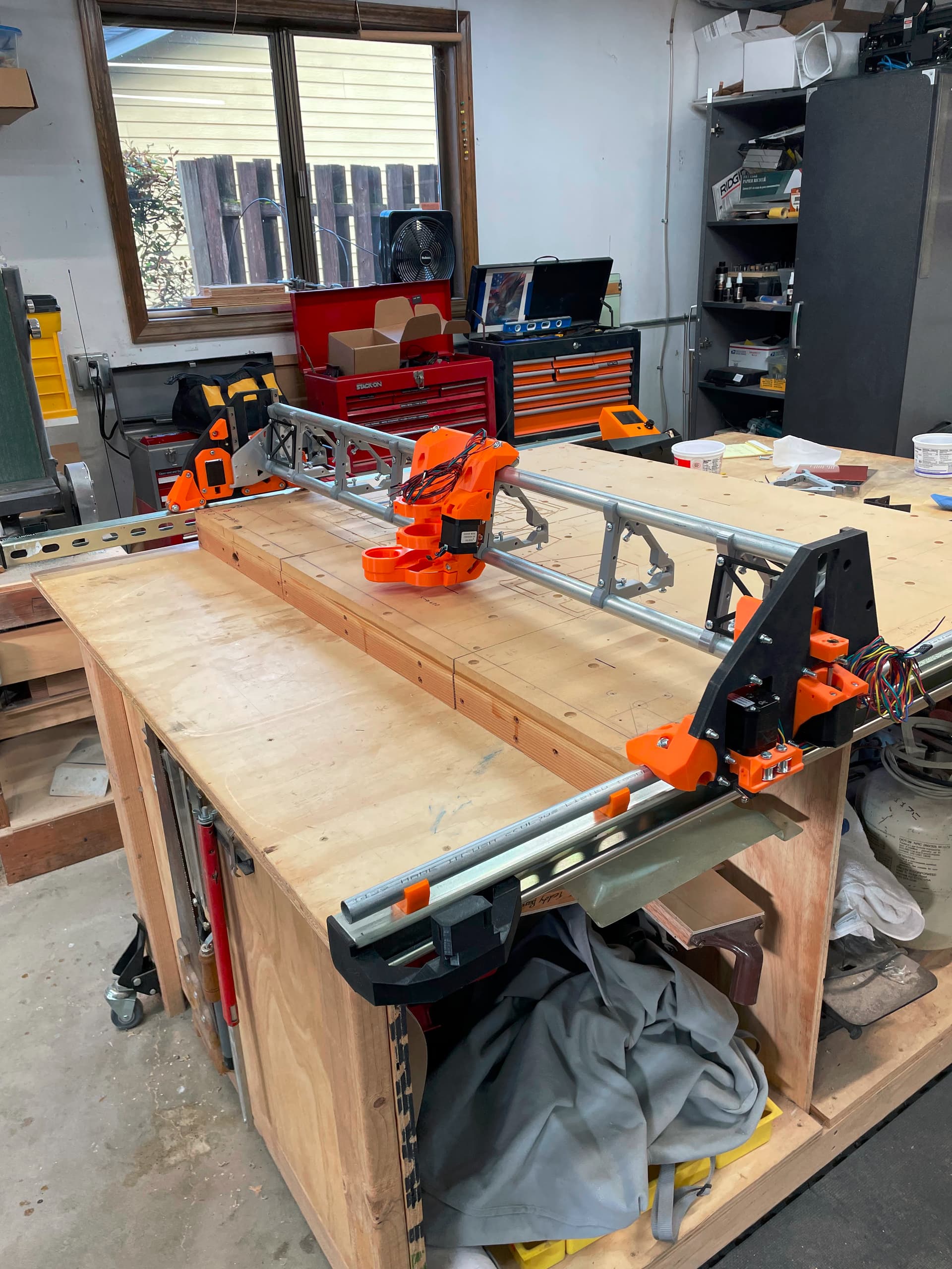
Since I’m using a non-standard size for both the X and Y axis I carefully assembled the two side assemblies and measured the distance between them. I also am using Doug’s unistrut side rails. In spite of measuring the distance correctly (so I thought) I cut the x rails too short! At least they were long enough to allow a basic assembly to get the REAL measurement, which I verified on the “calculator” tool in the documentation. I visited the Orange hardware store and bought more EMT.
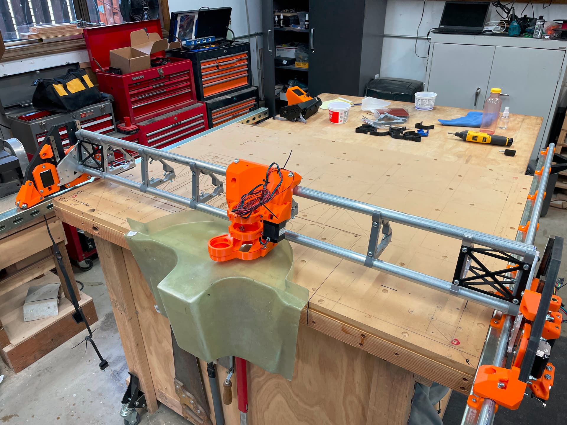
This glider panel has a tray attached to the rear surface and I can’t cut the front surface without some way to hang the tray out the back.
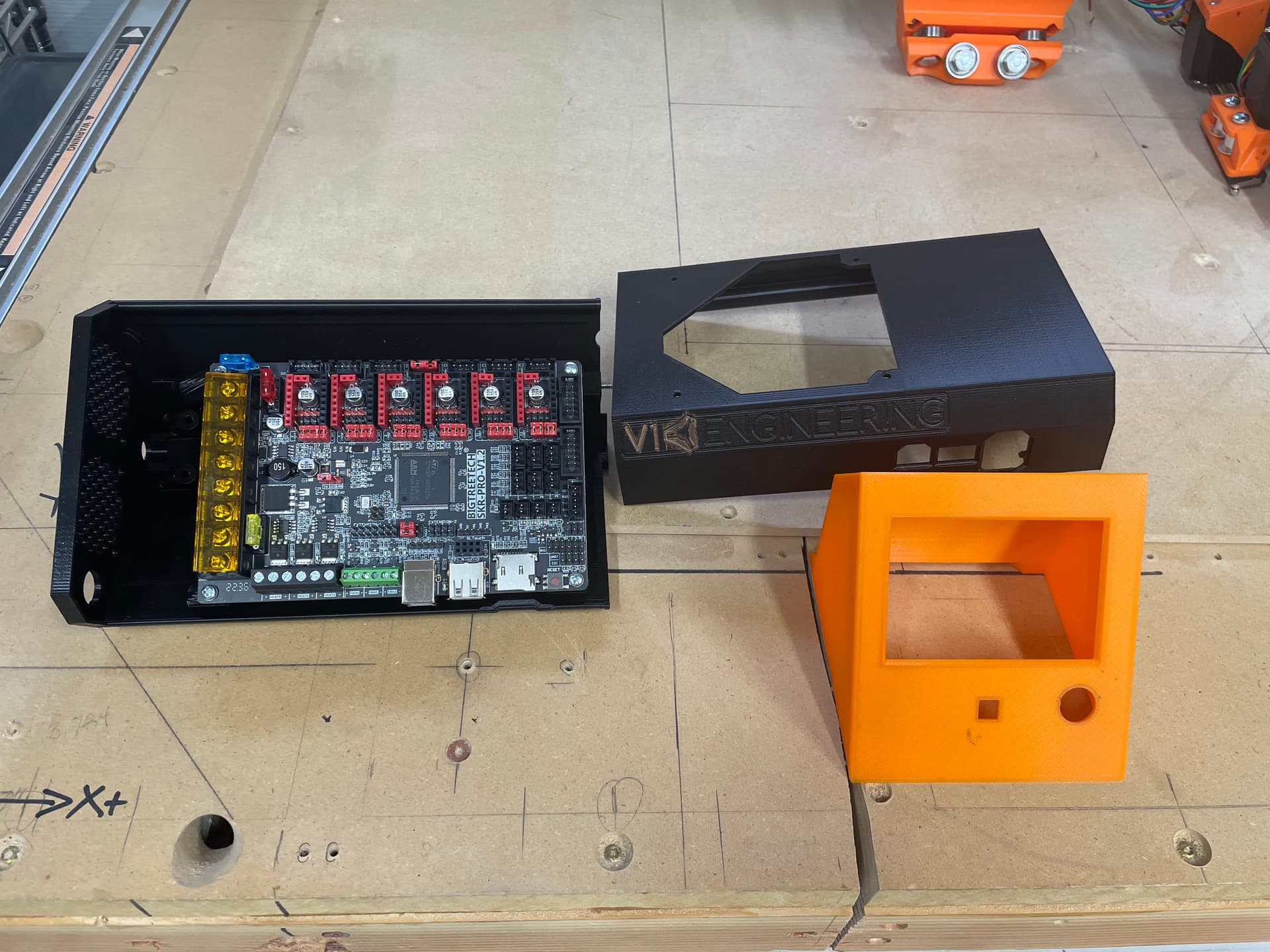
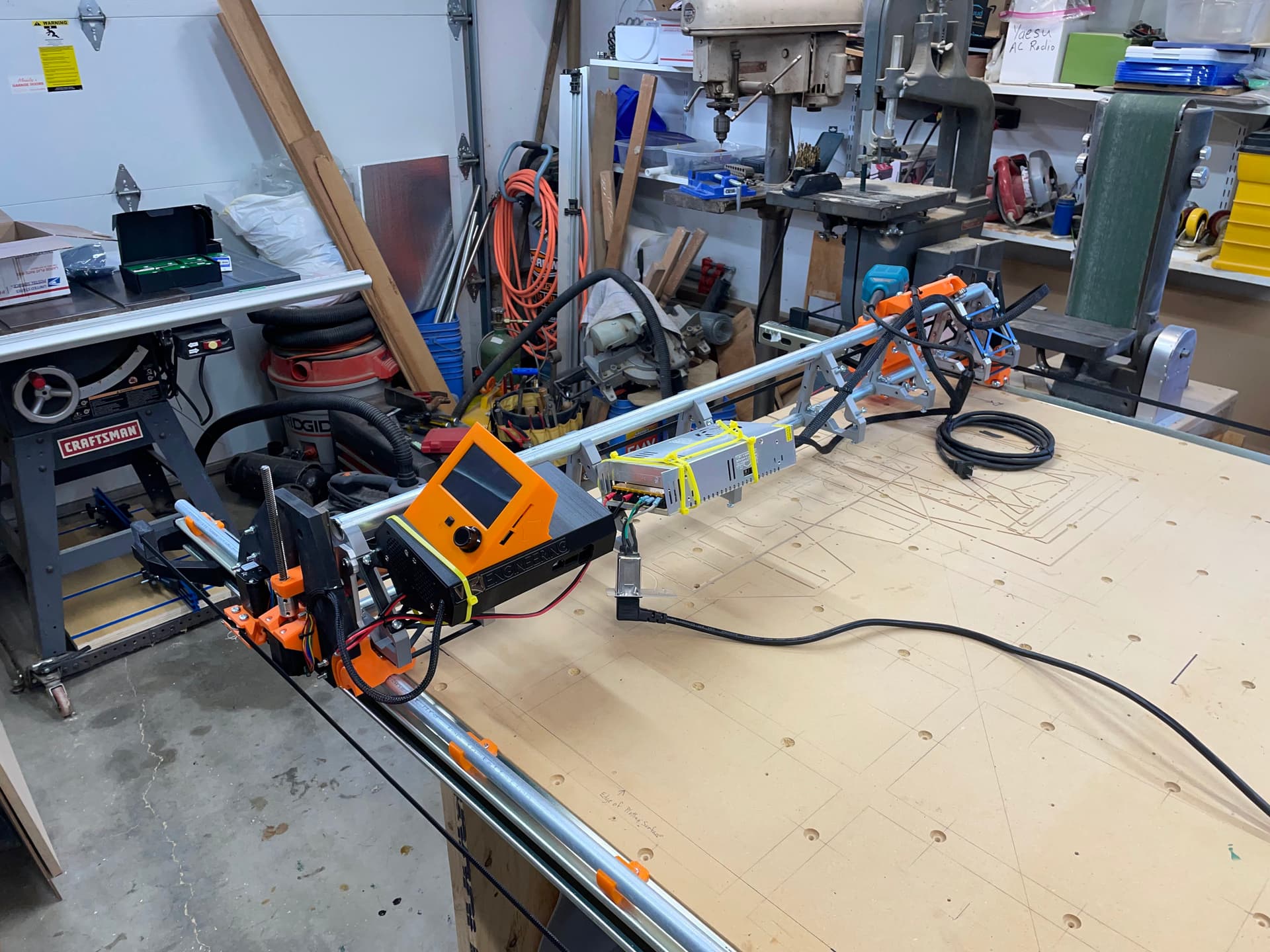
I’m putting the SKR box together now and hope to have a chance to move it a little, later this afternoon after Amazon delivers my belts. Whoo, Hoo!
I do have a simple (probably stupid) question: where are the Y1 and Z1 steppers located? On the left or right side assembly? I understand I can play plug-and-switch until I figure it out, but there doesn’t seem to be a clear explanation in the docs. The SKR documentation does explain which one get plugged where, but doesn’t say which stepper that is on the machine.
The concept is that the left corner where the machine will home to, or “0,0”, is X-min, and Y-min (and where Y1 and Z1 are located), and the right side is X-max, and the far end is Y-max.
It actually does not matter, so long as the end stops are with the associated motor.
As it happens, my Y1 is on the left (near where X=0) and Z2 is on the same side. I discovered that I’d wired the Z axis backwards to what I intended when I adjusted my home routine to level the gantry, which was the first time it actually mattered which was which.
If you need to make adjustments to the homing routines, then you may need to know which is 1 and which is 2, but for general functionality, it makes no difference.
Thanks guys! The belts arrived and are installed, I’m just checking out the controller firmware and wiring. I should have movement before I finish the day.
The first outage was probably an accident. The later ones might have been the power company toggling things to replace parts while fixing it. We lost power a few times over a couple of hours, and a friend a mile away was missing power the whole time. My guess is that the grid dropped them and then the power company was toggling our power to fix theirs.