AI for 3D design?

I am having trouble finding problems hard enough to really push the AI and I thought, maybe something physical.

After describing the problem I wanted to see what it felt like for tooling. This was my prompt (edited because original was dictated and it is awful to read):

Before we get to the first milestone, I want to discuss what kind of CAD software would be amenable to your processes. Normally, when I do 3D modeling, I use OpenSCAD — that’s my favorite way to work. I haven’t used FreeCAD, but I know some people do, and if you know how to drive it, I’d be willing to make it available. If we’re going to be collaborating and I’ll be doing some work in it myself, I might need your assistance talking me through how it works. But that’s another option.

I think Onshape, being web-based, isn’t going to be very amenable to your processes, though I’d be open to it if there were some possibilities there. I’m not going to pay for it, so the design would have to be open source — which I think I’m okay with — but that would be my third choice. Paid programs like SolidWorks or Fusion are out of the question, since I won’t be paying for those.

I’d also be open to some kind of pure 3D model — say in Python or Three.js, or some other rendering — that would show the shapes and maybe model some of the weights and gearing. Whatever platform you think makes sense there, whether that’s Python or TypeScript with web rendering. That might actually be a more convenient space than CAD software for spitballing different concepts and talking through expectations — gears versus belts and other design decisions. So that might be something to experiment with early, especially since it would help us brainstorm multiple ideas and converge on one.

The response:

OpenSCAD is the best possible answer for me, and it’s not close. It’s plain text, so I read and write it natively, changes show up as meaningful git diffs, and I can render it headlessly from the command line to PNG or STL to visually check my own work without you in the loop. The fact that it’s also your daily driver makes this the rare case where zero compromise is needed. FreeCAD I can drive (it’s fully scriptable in Python), but its workflow is GUI-centric and collaboration through it would be clunkier — I’d keep it in reserve for things OpenSCAD is bad at, like STEP export or FEM, if we ever need them. And you’re right about OnShape: web-based means I effectively can’t touch it.

On the Python/three.js idea — yes, enthusiastically, but I’d frame it as something other than CAD. What you’re describing is the engineering model: link lengths, mass budget, counterweight sizing, joint torques, gear ratios, traverse times — with a 3D view attached. I’d build it as a TypeScript/three.js page with sliders (joint angles, link lengths, stub lengths, payload, gear ratios) and live-computed outputs (counterweight masses, torque at each joint vs. NEMA 17 capability, margin, traverse time). That’s the tool for converging on a concept. OpenSCAD then answers a different question — “what exactly do we cut” — once the numbers have settled. The two don’t compete.

So my proposed division: three.js concept model for the trade-study phase, OpenSCAD as the geometry source of truth after.

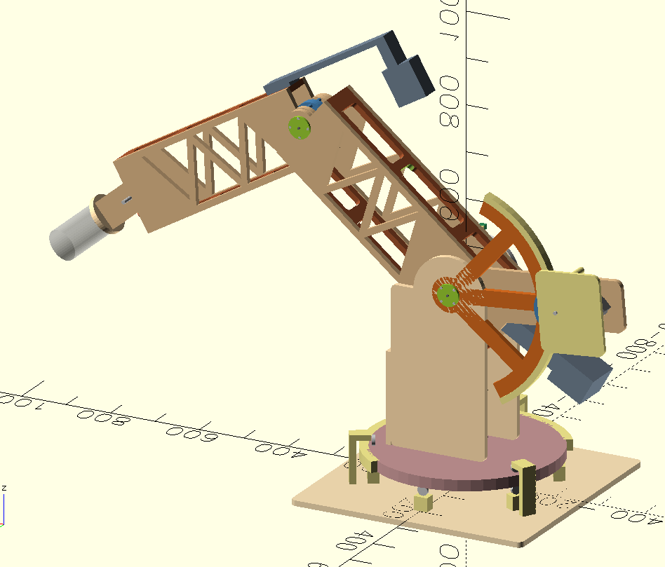
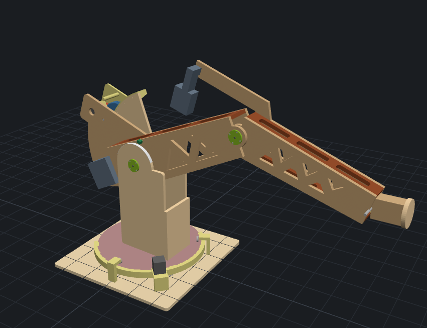
So now AI is generating OpenSCAD for me :exploding_head:
I did not write any of this (but I did have to notice some mistakes and tell it to fix).
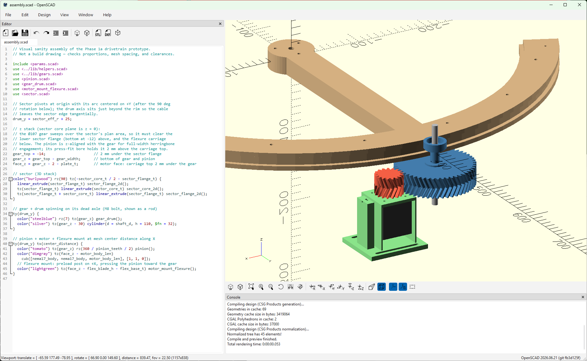
Was that supposed to have an additional herringbone gear set on the upper part?

Looks like a telescope positioner…

Lower part is a gear and upper part is a capstan, so total gear ratio is 150:1. There will be position feedback so if the capstan loses position (inevitable) it’s okay.

Nice. Claude helped me write a plugin for FreeCAD to make something one time. It’s more involved as I had to import the plugin and run it to create the model.

That is pretty cool, one heck of a tool and it is improving very fast.

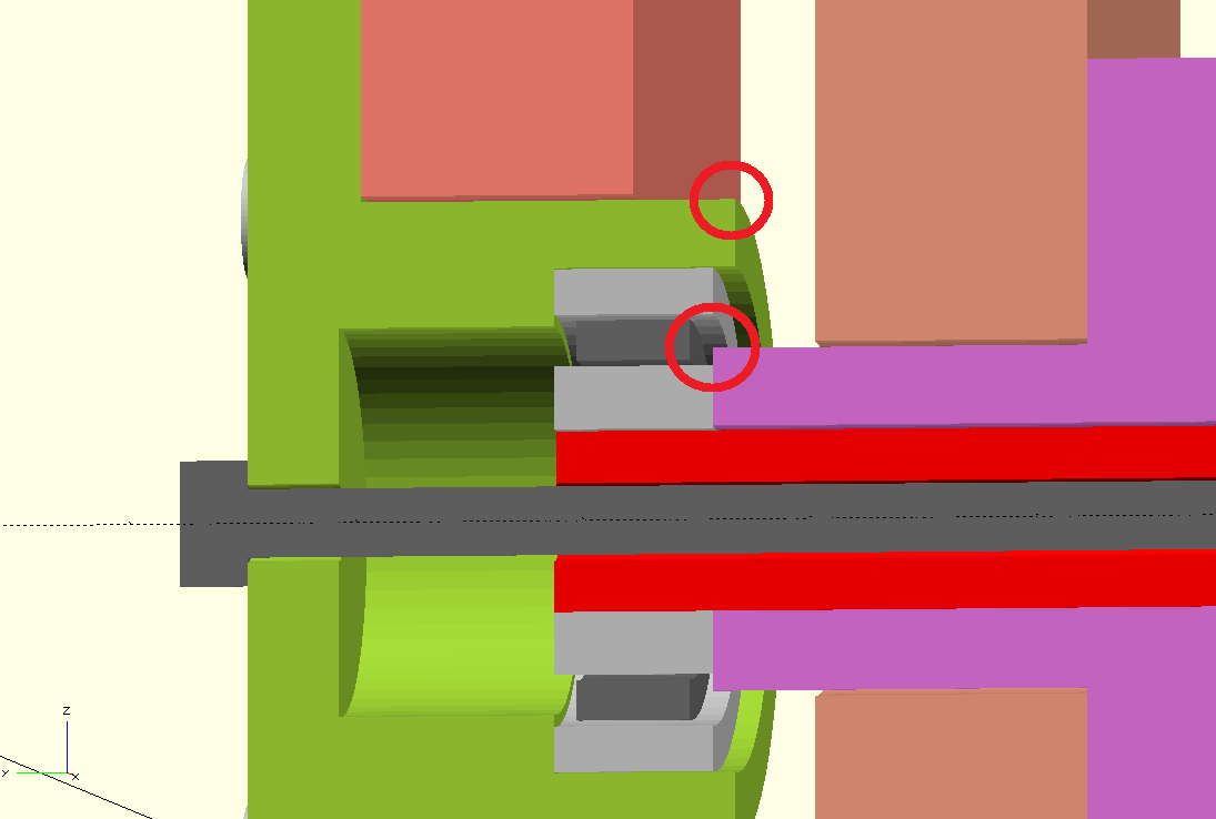
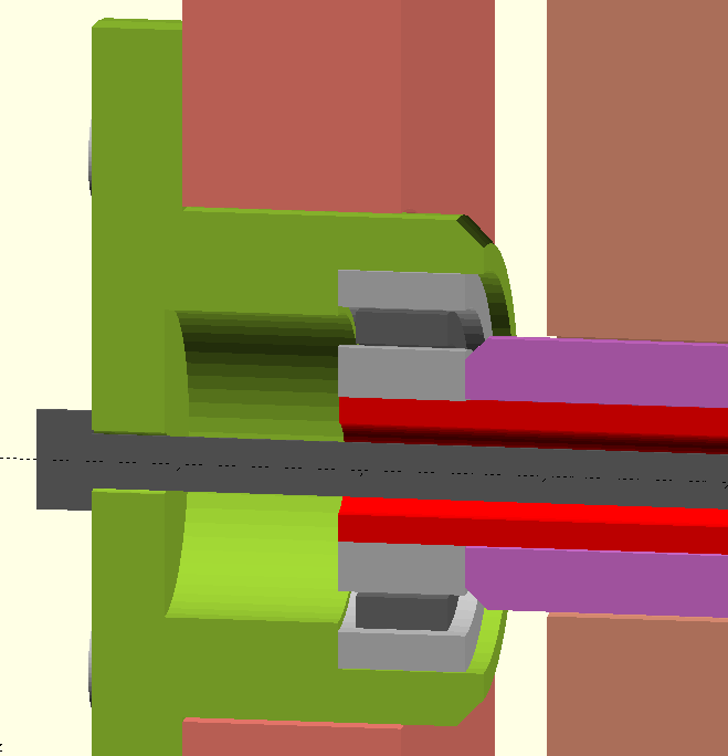
Chamfers and fillets are really annoying in OpenSCAD.

Now I take a screenshot and draw circles. “Add a chamfer here and here”

This is total insanity.

I’m looking at a plywood robot arm by the way

(This is still an early draft)

Needs 4 capstan robot legs. Keep vibing!

Running openscad as-is? or got a harness/agent able to scan desktop app as you markup stuff (something like sysinternals zoomit but with AI integration), to enable automated closed loop multi turn progress towards goal(s).

Just using as-is. But so far I’ve been keeping hands off the code myself because I don’t want to confuse it with changes of my own, and anything I do is probably going to get trashed anyway.

I wasn’t sure whether to make it public (yet) but what the heck
https://github.com/vector76/big_arm

And by the way this is an old “wish” of mine…

Ended up subscribing to anthropic this month, mainly to try out fable via the subscription. Was just using ChatGPT/Codex/Github-Copilot subscriptions before. Yann Lecun keeps talking about JEPA being better than LLM for modeling geometry, and problems that consider time. Recently been wondering if there’s a practical accessible model for machine/robot design (physical and/or firmware) type work like this.

Like the counter weights idea, wonder if the forces can be cabled to moving weights located near the base (side benefit of more stable base overall?). Then weight size/density doesn’t matter as much. Counter weight slides (like large cranes), or the counter weight cable leverage point?

Weights could be hanging jug(s) of water, heck… maybe dynamically pump water around to balance loads and minimize work motors need to do? “Hydraulic” based weights (cable attached) without actually needed to use high pressure hydraulics.

EDIT: struck out after reading your https://forum.v1e.com/t/robotic-arm/40158/2 post.

Curious to see what you and AI (Opus/Fable?) end up with!

:popcorn::popcorn::popcorn:

So far this is Fable. Maybe other models are as good but I have lots of usage, so why not.

(Fable might not be included in subscription usage after tomorrow.)

Fable had proposed this:

And here it is, calculating loads and stuff, to explore the parameter space and tradeoffs.

I am just beside myself, this is so ridiculous.

So, hey, make a web version that doesn’t have all the degrees of freedom, only the pose, and use the actual model.

Sure, here ya go:

https://vector76.github.io/big_arm/twin.html

(don’t look too close, it still has mistakes and still evolving)

That web view might really come in handy for simulating later.

Looks awesome!

Fable’s available via subscription until 19th :partying_face:, or so they say…

:popcorn:

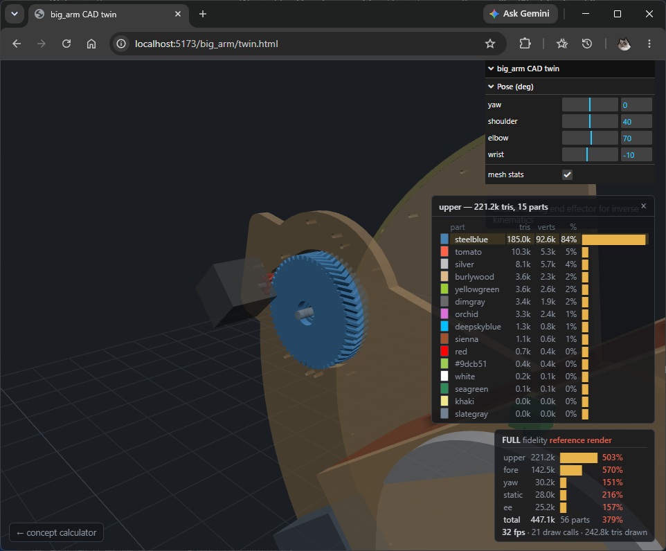
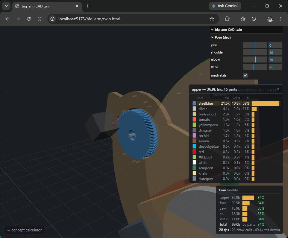
Yo @jamiek ! Dug around, like what you’re doing. Tried to contribute and shared pull request adding mesh stats (opus 4.8 extra high) before code radically evolved, too late already?

Let me know if you want more context about the mesh stats windows that auto zooms on selected part.

BEFORE 447k triangles :

AFTER 99k :

LGTM

PR #1 — “Make the twin cheap to draw, and keep it that way” (aaronse)

Verdict: solid work, merge-ready from my side. I fetched the branch and verified it rather than just reading it — details below.

What it does

  • Adds a $twin special variable (params.scad, default false) that coarsens tessellation on manufacturing-only features — the capstan groove sweep drops from 60 hull segments per turn to 8, herringbone involute sampling from 10 steps to 3, and various $fn values halve. Only export.scad sets twin = true, so print/cut exports are untouched. Using a -variable is the right call: it reaches lib/capstan.scad and lib/gears.scad through dynamic scoping without those libs needing to include params.scad.
  • export-cad.mjs now parses OpenSCAD’s --summary geometry output, enforces per-body triangle budgets (non-zero exit when blown), writes a stats.json next to the meshes, and gains npm run export:cad:full for a full-fidelity comparison render that’s allowed to overrun.
  • The viewer gets a mesh-stats HUD (toggle in the pose panel, or ?stats=1): triangles per body against budget, live FPS/draw calls, and a per-part overlay where clicking a part isolates it and flies the camera to it. It also fixes a latent nit — gui.onChange was firing setPose for every GUI change, now scoped to the pose folder only.

What I verified

  • The branch is current with main — merge-base equals your HEAD; aaronse already merged your shared capstan-cutter commit and re-baselined the budgets for the third drive.
  • The budget gate passes: export renders 140,800 triangles total, every body sitting at 83–87% of its ceiling — consistent with the stated “~20% headroom” policy, and matching the README’s 140k claim.
  • tsc --noEmit passes and all 23 unit tests pass.
  • The code reads like your repo — comment voice, helper idioms, and the part() color-as-semantics convention are all respected.

Things worth knowing before merging

  1. I verified numbers, not pixels. The capstan groove at twin fidelity is 8 hulls/turn of an octagon (down from 60/24) — the README claims “no visible difference,” but I haven’t eyeballed it. Worth one spin of the viewer (or npm run export:cad:full + compare) before taking that at face value.
  2. The “CI fails on the commit that caused it” comment oversells slightly: your only workflow is the manually-dispatched Pages deploy. The gate runs there, but nothing runs export:cad on PRs or pushes, so a budget blowout surfaces at deploy time, not commit time. A small PR-triggered workflow would make the comment true.
  3. The budgets are hard-coded in the script with a “ratchet down deliberately” policy — fine, just a convention to maintain.
  4. Minor: #ik-hint’s CSS top is hand-adjusted from 172px to 200px to account for the new switch row — it’ll need touching again if the panel grows.

The PR body’s “447k → 99k” numbers are from before your third drive landed; the post-merge reality is 616k → 140k, which the README states correctly.

Teaching AI how to build robot arms, you don’t happen to work for Skynet do you? :wink:

It would be a super clean design if you can put in a slip ring for the connecting wires.