I have just put together a new controller for my Estlcam driven mill.
While setting up the PWM signal needs to be 0-10 volts, so I purchased a signal booster that should be able to increase the 5 volts from the PWM to 10 volts output.
After testing the most I can get out of it is 8.3 volts set at 24000RPM.
There is a small adjusting screw on the 25 turn trimpot and I have turned that up and down without getting any higher reading, it will of course go down if turned enough.
Without being able to actually measure the RPM, I don’t know if I am getting the full speed as selected.
I have tried two of these boosters, both do exactly the same, so I don’t think it is that.
I took a measurement of the PWM signal from the Nano pin and it is almost 5 volts.
I added a 12 volt supply to the Nano board (Nano to Uno adaptor board) and it didn’t make any difference.
Estlcam will change the output when a lower setting is sent like s12000, but I don’t know if that is true speed.
I also changed the volt meter in case I had a faulty one, but both give the same reading.
Any thoughts on this, will it make a difference, am I worrying about nothing?
What voltage at the output do you get if you disconnect the VFD from the adapter? i.e. just connect a multimeter to the 10v output and try both 50% PWM to get 5v at the meter and 100% PWM to get 10V. Adjust with the multiturn pot. Assuming this works check the output voltage again with the VFD connected. If the maximum output voltage has dropped to ~8V on 100% PWM your circuit needs an extra voltage follower stage as the VFD is pulling the output down. Either that or don’t worry about it, 8.3V is ~20% down on maximum so your spindle will be 20% down on maximum revolutions…does that matter?
Was the converter one of these or one of these? I suspect the first and I also suspect the second might be better as it appears to have the second stage that the first omits.
I haven’t connected the VFD yet, I have done all the testing on the workbench unloaded, so really I should be able to get full voltage.
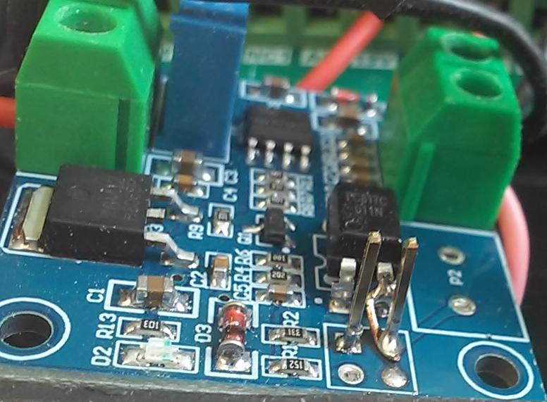
The booster I am using is this one.
https://www.aliexpress.com/item/1005004289977488.html
I have three of them in case I had a problem because it takes so long to get anything from overseas.
I have a meter wired into the circuit so I can see what voltage is being produced at all times that the spindle is activated, the meter is across VI1 and Grd.
Putting another meter across the PWM pin and ground I get about 4.9 volts.
The spindle is air cooled 1.5Kw so the minimum speed is set at 8000RPM so that there is some cooling, so that also reduces the range of speeds. I am not sure if a reduced high speed will be of any consequence.
Actually I have this one, it has some jumpres that the other one doesn’t have.
On checking the data on this model the jump selects between 5 volt input and 24 volt input
https://www.aliexpress.com/item/1005006005451729.html?spm=a2g0o.detail.0.0.40601rFg1rFgsx&gps-id=pcDetailTopMoreOtherSeller&scm=1007.40050.362094.0&scm_id=1007.40050.362094.0&scm-url=1007.40050.362094.0&pvid=704c7201-e8a4-424b-be58-e42db7abb852&_t=gps-id:pcDetailTopMoreOtherSeller,scm-url:1007.40050.362094.0,pvid:704c7201-e8a4-424b-be58-e42db7abb852,tpp_buckets:668%232846%238110%231995&pdp_npi=4%40dis!AUD!6.51!2.13!!!30.89!10.13!%402101ead817046251633988472e9cf2!12000036304654119!rec!AU!119122140!
Here is some info I found about the use of it.
(PWM to Voltage Converter Module 0%-100% to 0-10V for PLC MCU Digital to Analog Signal PWM Adjustabl Converter Power Module) 1. Description: The PWM transfer voltage module LC-LM358-PWM2V converts the PWM digital signals into 0 to 10V analog signals. It can be used as signal interface switching for PLC or other industrial control boards. The output voltage is regulated by adjusting the duty ratio of the PWM. The modules are small in size and easy to use in different places. 2. Features: 1>. MCU embedded technology 2>. Easy to operate, fine tuned by potentiometer 3>. Select the PWM signal input level range through short-circuit 4>. The module is smaller, easy to carry and use 3. Parameter: 1>. Work Voltage:DC 12V-30V; (> 100MA) 2>. PWM Receiver Frequency:1KHZ-3KHZ 3>. PWM signal input level range: The peak of 4.5V to 10V level. The short cap install in ‘5V’. This level is used for normal controller or 5V MCU The peak of 12V to 24V level, so inserted in 24V. The short cap install in ‘24V’. This level is used for normal PLC controller 4>. Conversion range:0%-100% PWM to 0-10V 5>. Allowable error:5% 4. Hardware Interface: VCC DC 12V-30V GND Ground PWM Positive of PWM input signal GND Negative of input signal VOUT Output Voltage 0-10V GND Output Voltage Ground 5. Operation instructions: After power on, without input signal, the output is 0V, so only input can output. The first time when the power is on, it is best to do a calibration debugging:Input a 50% duty ratio signal to PWM/GND and adjust the relative amplitude short cap. The frequency is 1KHZ-3KHZ, Measured VOUT and GND with a multimeter and it will display 5V. Adjust potentiometer to make sure display 5.00V on multimeter. This will calibrate your pulse signal to this module. When the frequency changes, the correspondences may be offset and need to be re calibrated. The output voltage can be adjusted by adjusting the duty ratio. The accuracy can be controlled by adjusting the potentiometer.
A DMM isn’t really the right instrument to see in detail what’s happening with PWMs.
DMMs integrate the measurement and are slow. They’re a crude tool for this work.
To really see what is happening you need to put an oscilloscope on the signal and watch it both unloaded and when connected to the VFD.
Unlike the others, that one has an optocoupler. I have that one and hacked it to remove the shared ground so that the PWM/controller is isolated from the VFD. There are more expensive versions that have isolated inputs… e.g. https://www.aliexpress.us/item/2251832802576963.html
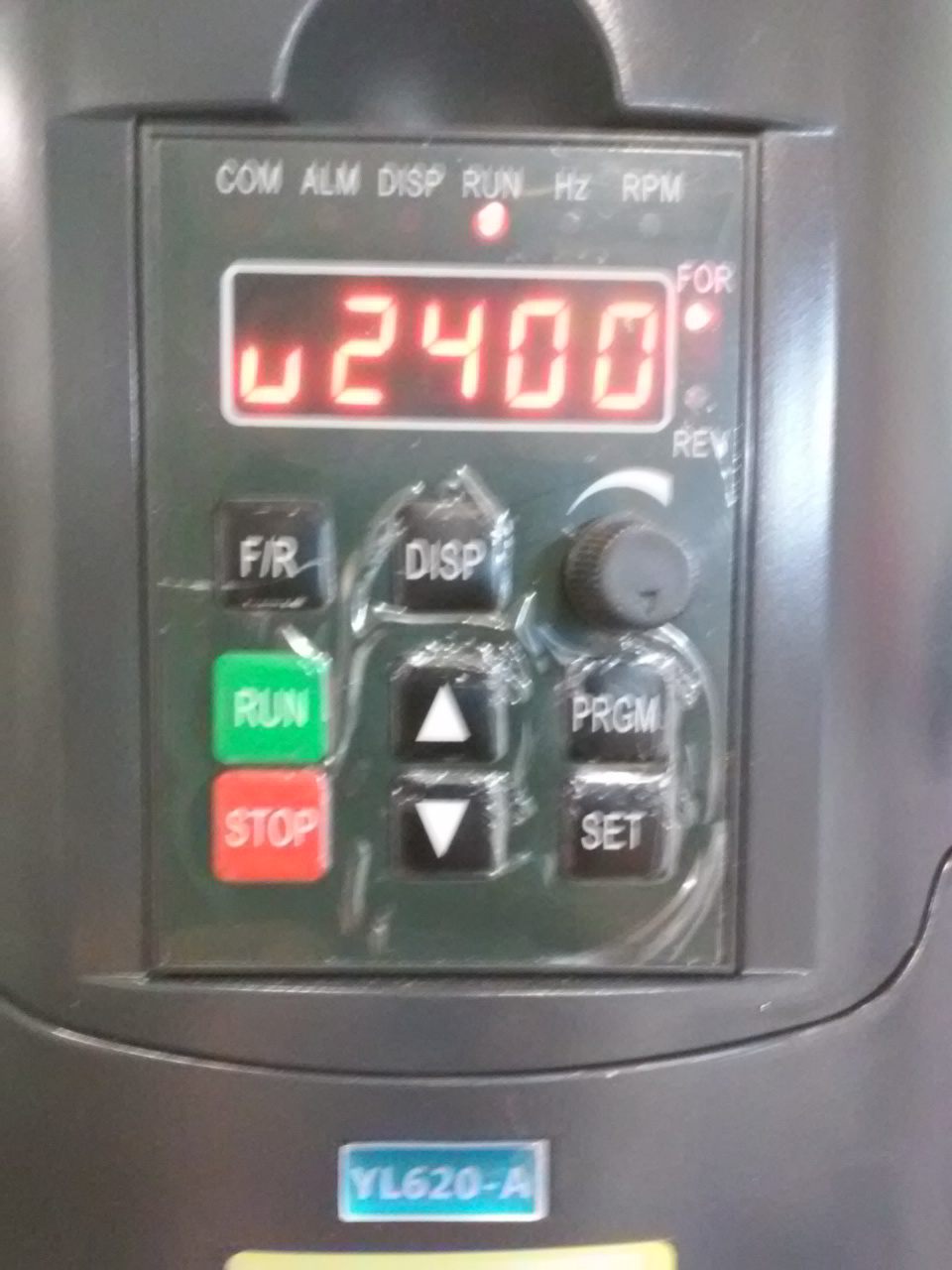
What does your display read?, 400 = 24k rpm. You can also have your VFD show RPM:
Optional LCD RPM instead of Frequency (yl620-a)
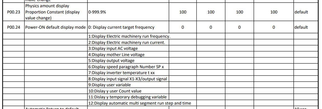
P00.23 = 60 |60hz (line) x 0-400hz = 0-24k rpm (default=100, 0-400hz)
P00.24 = 9 |Show 0-24k rpm (instead of 0-400hz, default=0)
…and what are your Setup : Controller : Spindle settings?
My machine is not finished yet, but I have the VFD and the control box for the machine is now ready for use so I could set the VFD up and test it out before fitting to the machine.
I guess I would have to connect the spindle as well so the VFD has some load?
My other machine has the same VFD and spindle, so I was intending to copy those settings as it has worked well for the last 7 years.
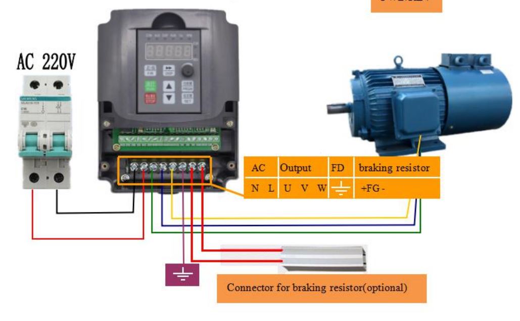
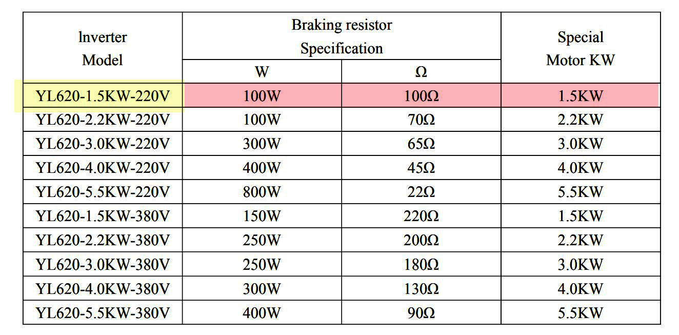
I have just received a couple of resistors I ordered for braking, not sure on what is needed there, the manual doesn’t go into much detail (VL620-A) I got two because I intended to add to both VFDs.
I had forgotten that the drive itself can display RPM, so I can test it from there.
Also after reading a bit more on the booster, instead of using a 12 volt supply I could use the stepper supply of 24 volts, maybe that would give a better result?
YL620-A settings.zip (583 Bytes)
YL620-A manual 1.5KW-220v.pdf.zip (725.9 KB)
I would like more info on this please.
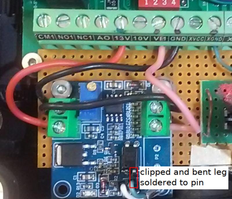
Did you cut any tracks, which pin did you bend and solder and which leg did you attach of the opto coupler?
I seem to remember that more than 12v is recommended (my 13v VFD source works fine).
PWM goes directly to the second pin (instead of via input trace, pin 1 and jumper) and ground goes to the first pin (/original input trace) which is soldered to the, severed from the ground plane, optocoupler input ground leg… FWIW, the PWM input routes to the left input leg of the optocoupler via a 330 ohm resistor.
P00.23 = 60 is the math 60hz x 0-400hz = 0-24k RPM
P00.24 = 9 displays it as ‘u value’
My 12 volt measures a maximum of 11.9 volts, it wont go any higher.
The line frequency, is that referring to the household mains power line? In Australia it is 50hz
Thanks for the detail on P00.24, I understand now.
And also for the further detail on the booster.
Yes.
So if I have 50hz not 60hz it would make the output only 20,000RPM, is that correct?
P00.00 = 50
P00.01 = 1 (4:By user application program control)
P00.02 = 0
P00.03 = 2
P00.04 = 400
P00.05 = 400
P00.06 = 140
P00.07 =
P00.08 =
P00.22 =
P00.23 = 50
P00.24 = 9
P00.25 =
P01.00 = 1
P01.01 =
Braking section
P01.08 =
P01.09 = 15
P01.10 = 0
P01.11 = 2
P01.12 = 0.6
P01.13 = 20
P01.14 = 15
P01.15 = 3
P01.16 = 100
P01.17 =
I changed to 24 volts to supply the booster and it made no difference.
It’s gotta be 24k max RPM / 400 max hertz = 60 and hertz x 60 = RPM (e.g. 200 x 60 = 12k). I’m not sure where I got the 60hz from, the VFD doesn’t care if the line voltage/mains is 50 or 60hz (I’m pretty sure P00.00 is Main/400 not mains).
When I get around to setting it up I will copy what settings I made on my other one years ago, it has been working great for a long time. Only changes will be for the braking, I will add that feature to both of them.
The resistor is pretty big and wont really fit comfortably inside the case and I am sure that it could also produce some heat, so I will mount it on a aluminium plate to act as a heatsink outside the case.
I have taken a guess at the settings and added them to the config file.
Well that was a nice tour around the houses wasn’t it!.
Everything that followed has nothing to do with your problem that the converter boards you have do not seem to output 10v with 100% PWM…or have I missed you achieving that?.. it’s all good stuff but not related to your fault.
I am a little concerned by this

What does that Chinesium mean I wonder? Two different devices? There are two different prices.
Which did you order?
If you connect the PWM input to +5V and ground (or a genuine 5v 100% PWM signal) and the input power connectors to Vcc and ground then you should be able to adjust the multiturn pot to get +10V across the Vout and gnd.
I assume you are using a standard Estlcam arduino pwm output for your pwm signal source and not something that is switching the ground like a n-channel mosFET.
I bought the PWM to voltage,
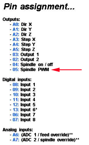
I am using the PWM output from the 05 pin of the Nano, the PWM output pin as used by Estlcam.
I have tried several Nano (6 in fact) and all give the same result, so I don’t think it is the Nano. The booster I have 3 of them and tried all three, same result.
The power supply to the booster was 11.9 volts from a separate power supply from the main supply of 24 volts, sharing a common ground. I change over to the 24 volt supply to power the booster because I couldn’t adjust the 11.9 volt supply to reach over 12 volts, same result.
I am trying to get the electronics system ready for when I can finish off the rest of the hardware as I am waiting on parts to arrive from overseas. The X carriage, Z axis has been completed, waiting on ballscrews and stepper motors to come for the Y axis, and a stepper for the X carriage.
My old machine has the same electronics except for the booster which I made myself from Christians circuit. shown in Estlcam 11
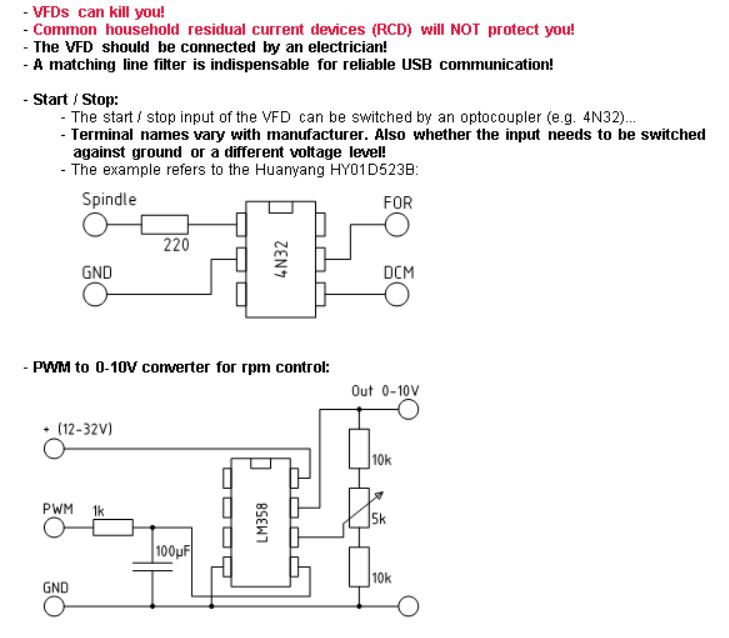
and the output displayed on that machine is actually a little over 10 volts. I guess I could make another one and try that, but the circuit is actually using the same chip so it is probably much the same circuit.
Sorry for the house tour Mike.
OK. Back to basics. I suggest you take one of the booster boards and connect it as I suggested in my previous post - from a separate 12v supply, totally disconnected from any 24 to 12v device and see if you can get 10v at the output when connecting the PWM input to +5V. If you cannot get that then the booster boards are not doing what they should.
Even though the LM357 is not a ‘rail-to-rail’ op-amp 12 volts should be all you need to get 10Volts output from the booster.
Are you sure your VFD doesn’t have a +5V PWM input? - most do.
In between posts I tried using a 12 volt battery for the power supply, for the booster and hooked up a Nano only powered by the USB power, no other gear attached. I used Estlcam to send out the signal and the most I could get was 9.6 volts which is the best so far.
Tomorrow (actually today, it is just after midnight here in OZ) I will try with a 5 volt signal input as you suggest and see what I can get out.
It is actually a LM358.
I have a YL-620-A VFD and it needs 0-10 volt