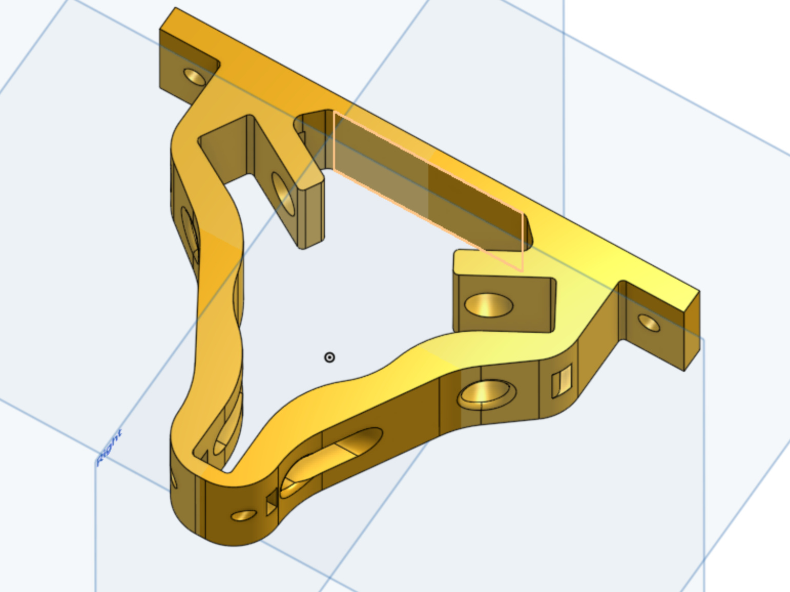
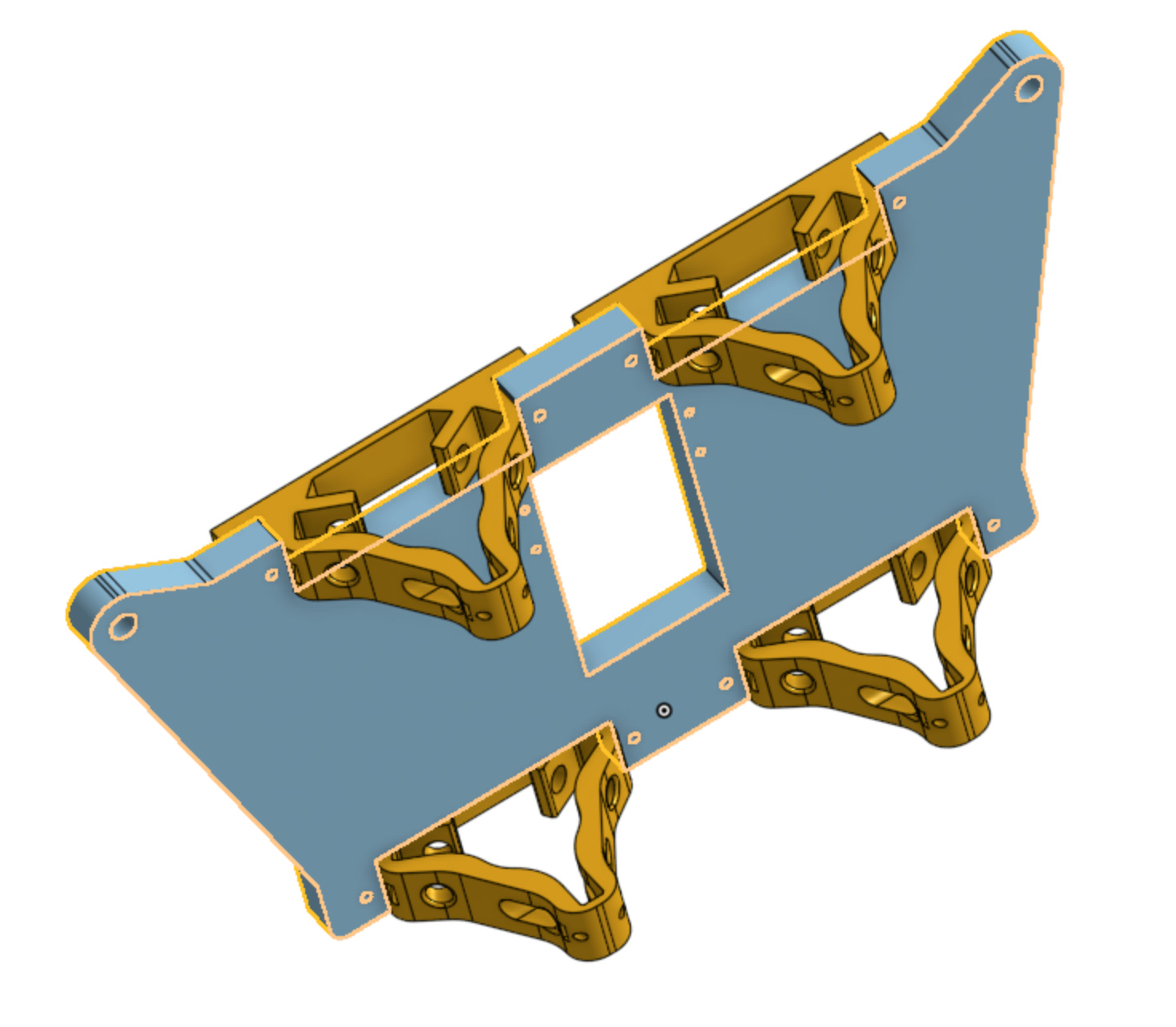
I take that back, if we cut notches out of the y-plate, the brackets can be mounted on the inverted side, bringing the z tubes much, much closer to the plate.
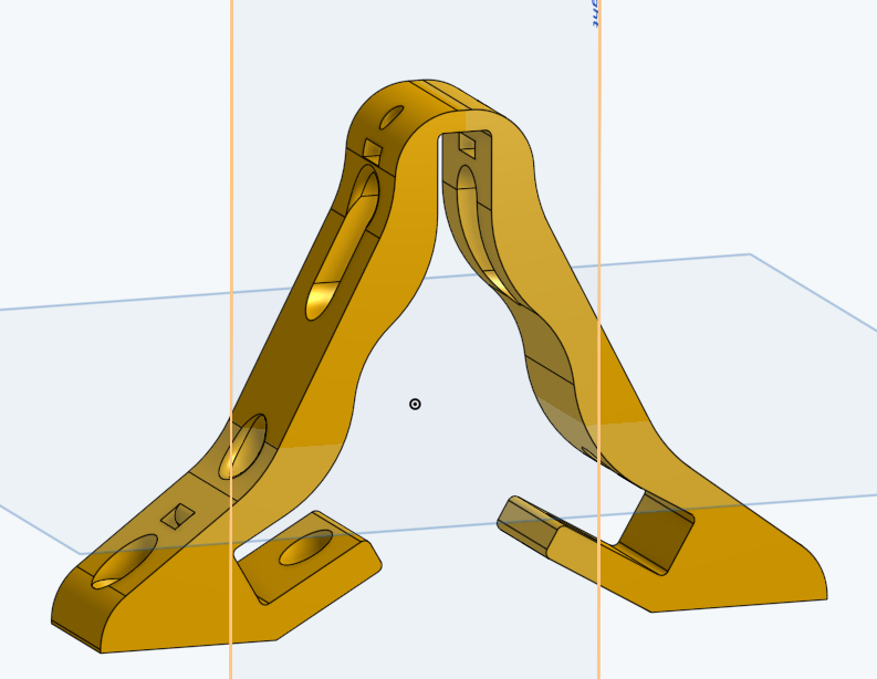
Here’s the proposed piece. This moves the Z-tube as close as 1mm from the y-plate, but the mounting tabs can be shifted backwards so that the Z-tube will have more clearance. Is that desirable, though?
I would recommend modifying that part to reference off the inside face of the plate rather than the outside.
All the current LR2 parts that attatch to the Y plate reference on the inside face. This eliminates any reliance on or limitation to the thickness of the Y plate.
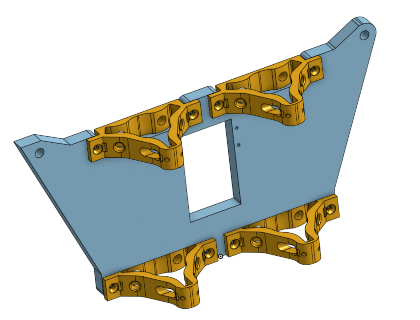
This seems like a doubly valuable upgrade. With the tabs in the new location, the same part can be used on the spindle platform, bringing the X-tubes 1cm closer to the plate.
P.S. Note to self, the Z tubes need to have some clearance for the belt to pass behind them. This might be substantial to the point of eliminating all the gains.
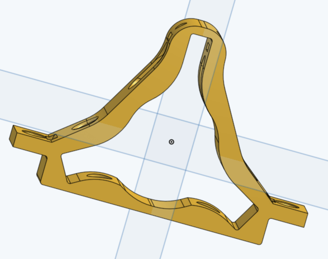
Note that I got rid of the recess. That was because ultimately the distance of the tube from the plate is driven by the need to allow clearance for the Y belt. It would take a further redesign to get this sorted out, and it’s likely a major change since it involves new belt geometries, and not just an optimized block.
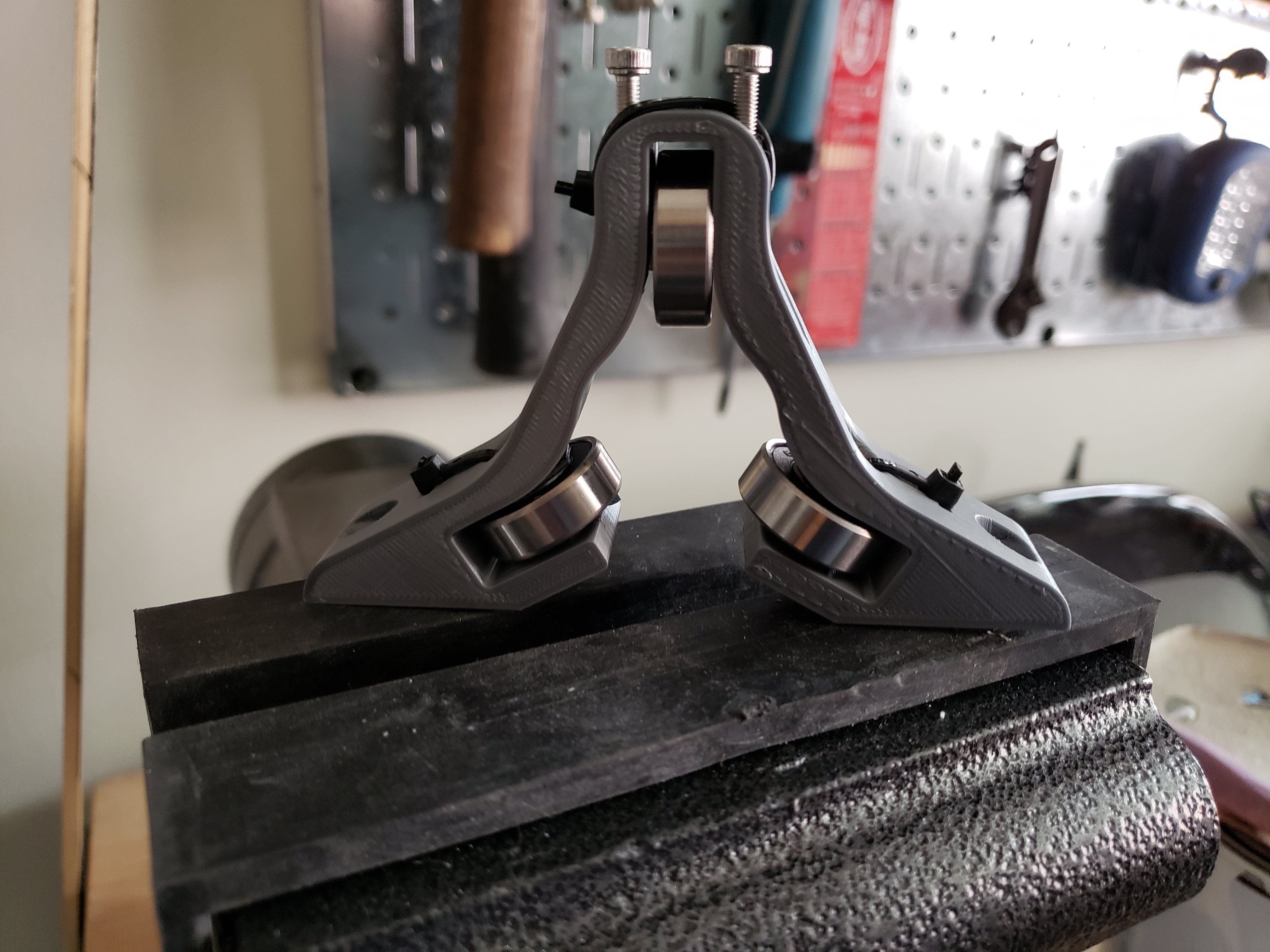
Note in the assembly how the bearings are retained by zip ties, but the zip ties are non-load bearing. The two screws at the top adjust the pressure on the rail, and from my tests I can build an unreasonable amount of force.
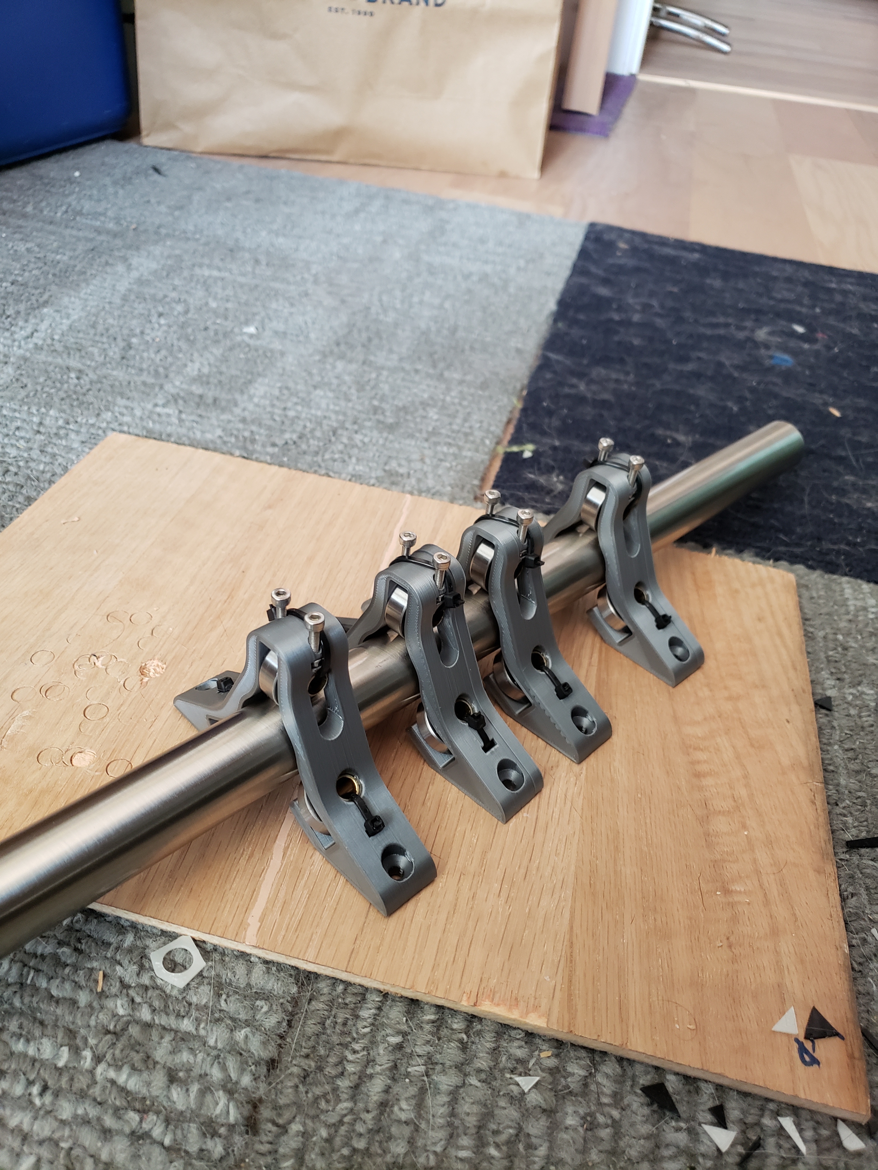
It comes in two variants, a 1/2EMT to a little larger than 1", and a little smaller than 1" to 1.25". The reason there’s some overlap is so that one size bearing block can do an entire assembly. If it’s for a small lowrider, then 1/2 EMT for the Z and 3/4 EMT for the X. And if it’s for a large lowrider, then 3/4 EMT for the Z and 1" for the X. And if it’s for a large, stiff build, then 1 EMT for the Z and 1.25", for the X.
Good idea. I have been dicking around with material sizing and like the idea of a modular system. Given a typical 0.065in wall 1" vs the same 1.25" is half the deflection (1.25" stainless with a 1500mm span yeilds 0.5mm deflection with a 6kg midspan weight, and 1" is 1mm).
For the purpose of accuracy do you think it would be easier to have captured bearing axles at all 3 locations with the addition of your tensioner idea. If the model was parametric, then you could easily produce tube sizes ever mm from 25-32 and use the tensioner to pick up the slack. Also the tensioner would add a preload capability to snug things up.
I suppose another item would be, can the lowrider be calibrated with a software mesh compensation at midspan?
Also, all bearings should be fixed with bolts. Vertical loads are dead weight taken up by the top, lower side bearings take up the cutting forces for y cuts and z cut plunging
Do you mean a tensioner at each of the three bearings? The problem with that approach is that there is no longer a dependable reference point for the tube. This would make alignment very challenging (albeit not impossible).
But I’m not completely sure I understand your question, so lemme know if I got it wrong.
Yes, in theory, but in practice it might take some iterative learning of some kind. Recall that that compensation would be variable based on the forces in that particular cut pass. So for a coarse cut the forces are higher and thus the
Worse, all this is dependent on the cutting tool, the work material, the feed rate, the spindle rate, etc…
It’s definitely deterministic, but I don’t know how to determine it with any precision. It might take some very sensitive instruments and at that point stiffening the structure is probably the far lower effort solution.
Would make for a fun hobby project, though!
In my design, all bearings are captured in place by the plastic. The axles have a little play in the axial direction, but that’s orthogonal to the bearings and shouldn’t have any impact. What do you see as the advantage of adding a bolt to hold the axle in place?
The downside I was looking to solve was that bolts add inertia, and inertia causes slop because the stepper-motor dynamic model assumes instantaneous acceleration/deceleration. The more inertia we add the less accurate this simplified model is.
I suppose I was rambling. From your photos it appeared that a zip tie was all that held the bearings against the tube. Your model shows bolt locations but maybe the bearings are more a fixed with a zip tie than I suspect.
I figured if the bottom 2 bearings were fixed bolted and the top was bolted with your tensioner you could have a quick parametric design for each mm diameter tube. The range between each mm (or half mm) could be taken up with the top bearing tensioner.
On the mesh I was over simplifying the 3D mesh to simply account for dead weight and sag from the router sitting mid span. Not to deal with the effects of cutting.
Lastly, is carriage weight a big deal for wood cutting? I assume the feeds are 10-20mm/s with low acceleration to limit strain in the router. Sorry I have a lot of assumptions, I’m building my first cutting cnc (second cnc) and only have previous hobby experience with manual lathe/machining world. So take any of my comments with a grain of salt.