Adding smarts to the MPCNC

There are some of these closed loop, BIGTREETECH S42C v1.0 42 Stepper Motor Closed Loop Driver Board with O | Biqu Equipment that will work as is but I’m not convinced that is the best solution currently.

The smarts…above my pay grade currently.

If I were to make requests though, the laser thing that seems pretty common would be rad. Where it takes a picture and moves the gcode to fit the material position. Seems like a very solid step one to some real smarts.

Smarts and laser targeting systems… It’s almost like you don’t actually pay attention to the movies any more…

2 Likes

Not really. I built it, but never put in the work required to assess its accuracy, and I have never used it while cutting anything. It was a little finicky, and definitely needed some iterations to make it work better.

I also experimented with closed loop steppers (not on the MPCNC but for 3D printing). I attached some encoders to the X and Y steppers on my Prusa i3, and made some measurements. My conclusion was that the steppers were really accurate, even at very high speeds. (The Trinamic stepper drivers may have something to do with that, they seem to be quite smart). The precision of extrusion seems to be a much more important issue in 3D printing than the X/Y/Z motion.

For the MPCNC, I did quite a bit of research into precision. The belts seem to be one of the largest sources of inaccuracy. Another is tilt of the router. A closed loop loop stepper that has an encoder on the shaft cannot compensate for those. A closed loop stepper also tries to correct for positional inaccuracies all the time. I think that gives a lot of potential issues with undershoot, overshoot, and extra “wobbling” / vibration.

If you just want to detect missed steps, then simpler approaches are possible. Trinamic drivers can detect missed steps for example. You could also try mounting an acceleration sensor. When things start to go wrong, you often get a lot of vibration that you can measure this way. I never tried that myself though.

His machine is already juiced up on its own firmware.

I have not tried the closed loop steppers. But I have a lot of experience in unmanned ground robotics (driverless cars). As soon as you use closed loop, you are replacing the open loop accuracy and resolution with the closes loop sensor accuracy. There isn’t a good way to combine them. Open loop steppers are extremely accurate and precise until they skip steps.

Once you skip steps, you are likely to already have lost your work piece. But even if you managed to skip away from the work, the closed loop sensor needs to be super accurate to be able to get you back on track. And then, because you are already pushing the machine so hard, it won’t be long until you skip again.

Additionally having sensors all the time means that you have the risk of the closed loop sensors thinking the machine is out of place, even when the steppers are not skipping steps.

So that is where I would set the goal posts. The open loop needs to be accurate and precise enough to be good enough for all the milling. Because even though you are controlling steppers, the difference will always be in the sensors. If there is noise, or latency in the open loop sensors, then you will have to accept that as the truth.

The steppers with the built in encoders seem like they would be much more accurate than any camera based system. Our ground vehicles all has expensive camera and lidar systems on them. They also have expensive inertial sensors. But they also all have wheel encoders. The wheel encoders are 100x cheaper, and 10x more accurate than any of them. Even considering the occasional wheel slip (which def. messes things up, but is recoverable).

Our standard system has 100 micro steps per mm. The steppers are not that accurate, because 1/16th microstepping has some noise. But conservatively, whole steps are 6.25 steps per mm or .16mm. That would be impressive for any closed loop sensor. But it is also able to “measure” that very fast (650Hz at 100mm/s), with bearly zero latency. Cameras are going to be 30Hz or 60Hz, and then you have to process those images. A very fast computer and algorithm (like the nvidia graphics card cuda optimized alg.) Would be able to process the image before the next one. So 30Hz or maybe 60Hz is close to the max and you’re not talking about a raspberry pi anymore. All those big fat images need to be moved around, which is high speed buses. If you are expecting very high accuracy, you will beed high resolution, which increases the size and the processing time. It is a really difficult problem.

3 Likes

Thanks for the update and info, Peter.
Helpful insights about sources of error. In the present case, I am just considering closed-loop to prevent missed steps, not necessarily to improve accuracy, which is already very good. I like the idea of just getting a stronger stepper motor and a Trinamic driver that can detect skipped steps and hit the pause button for me. And a “rumble sensor” is a great idea.

Thanks for the problem-solving and ideas, Ryan. I already put a lower-pitch lead screw on (1-start, 2mm per rev), to prevent the heavy spindle from falling when the stepper power is off. I like that pitch and want to keep it. I think the reason I am skipping steps sometimes is just down to the sheer weight and inertia of the spindle (1.5kW water-cooled, weighs about 10 pounds) and the specific shapes I am carving. It is definitely harder to manually screw it in the up direction than down, using my fingers on the coupler.

Although it is warmer than usual here in Ireland, I have a water-cooled heatsink on the Z motor that keeps it below 30C, and a fan on the stepper driver that keeps the IC in it at 53C or less. (would an overheated stepper driver cause skipped steps?)
I had just cleaned off and re-greased the leadscrew before my most recent fail (see photo below), and checked that all the Z axis rails/bearings are sliding freely without slop or binding. I have done a fair bit of tweaking of the relevant variables to optimize speed and torque for all three axes:
-microsteps
-stepper driver current setting
-max speed setting in grbl
-acceleration setting in grbl
(and upped voltage to 40V, and increased max pulse rate dramatically by going to the Teensy controller.)
I am often pushing everything close to the limit.

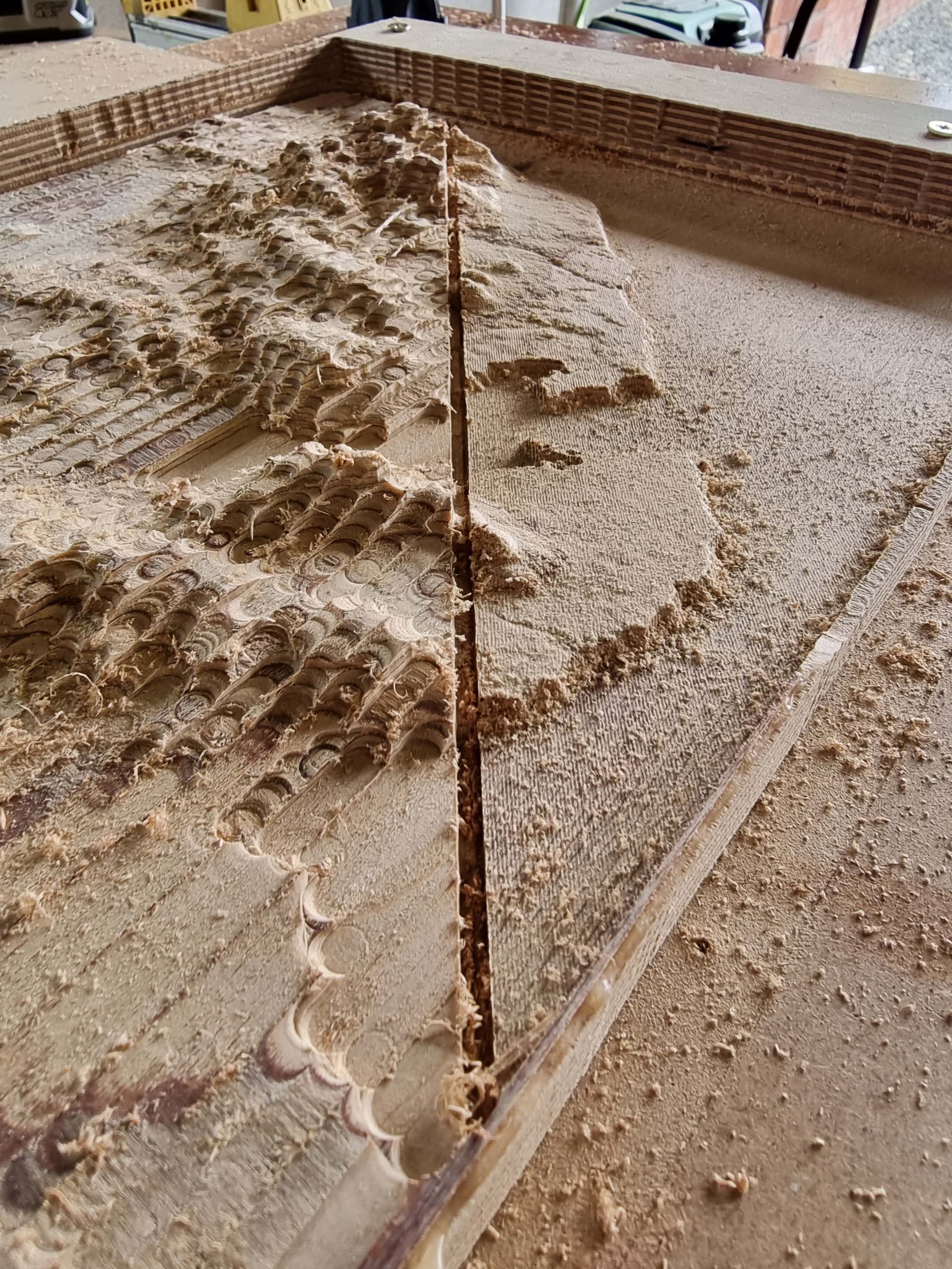
Here is what lost Z steps look like. I also heard a difference in the sound, due to the finishing bit carving a suddenly deeper cut. But because I had not been vacuuming up the dust, it took me about 4 passes to cop on that there was a serious problem.

More smart ideas about smarts, please!

It depends on the driver. Drv8825s will just power off if they get to hot. That really sucks. The trinamic drivers and Marlin will reduce their holding current if they get too hot. That can lead to skipped steps, but they are at least trying instead of quiting like the drvs. IIRC, you have some big, separate drivers. I have no idea on those.

1 Like

Great food for thought, Jeffeb3! I am often referring to Artificial Intelligence as Artificial Stupidity when it gets it wrong. I seem to recall Dui ripped out his S42B closed-loop steppers when they began fighting each other.
Issues of noisy sensors, too-slow feedback loop, data overload if processing images, are all good points you make. A wider safety margin on an open-loop system may be the right answer for now.

I think there are two areas here that are related but worth distinguishing: One is closed-loop (basically servo) control of the machine, and the other is closed-loop refinement of the workpiece.

For the servo control, the accuracy is going to depend on the distance between the point of measurement and where the action is happening. Closed-loop steppers will not have information about the deflection of the machine, whereas a DRO mounted to the router will include deflection of the tubes but not fully capture the tilt of the router. The multiple tape measure approach could use the measured points to virtually measure the tip of the cutter, and then you’re that much closer to measuring the true cutting position.

Measuring the workpiece is a different philosophy. I’m thinking something very different like suppose you were grinding a surface plate. You would have some method of measuring flatness and then the software generates code to selectively grind the high spots. Or if you are making aspheric optics, you have some evaluation methodology and you generate grinding motions from the aberrations.

On a more basic level, if you wanted to cut out a contour that was precise with lots of zeros, you could sneak up on the desired perimeter shape, like people who do woodworking by hand (I’m told). Leave some material behind, measure it with a microscope, and come back and take off a little more, and repeat. This transforms the accuracy problem into a repeatability problem, and repeatability can be orders of magnitude better.

My line follower I would consider a first baby step toward closing the loop around the workpiece. It’s mostly a demo to stoke the imagination and not intended for production, but I think it’s within this general area.

Servo control of the machine and closed loop refinement of the workpiece are independent. You could use them together or individually, although closed loop refinement of the workpiece might reduce the usefulness of servo control of the machine, since accuracy no longer matters and repeatability might be just as good on an open-loop machine.

One of the problems is, where is the ‘smarts’ supposed to reside? Moving the tool based on measurements means there needs to be a host program somewhere to close the loop. I had put it into OctoPrint as a plugin, since that seemed quickest, but for advanced methods perhaps it would need to be a standalone program with a gcode sender module and a calculation and optimization main loop. I think this is one of the barriers, since it is nontrivial to build this even for a simple job.

6 Likes

Thanks, Jamie, for helping us differentiate and refine what “smarts” might mean for CNC. And thanks for sharing your marvellous line tracer! I wonder if you were inspired by Glowforge’s laser cutter, which seems to have some features like this. They were the first (to my knowledge) to add a camera to a laser cutter to make it smarter and easier to use, such as cutting or engraving along a traced sketch. You are helping CNC get to that level.

I like this thought! Now, how to automatically ‘sneak up’ on the ideal carving?

1 Like

Good comments above. I have spent alot of time diving into MPCNC error. Think just pushing string pots around with a basic core under no load. As someone posted above, about .15mm seems a good estimate. Maybe a little better? 0.1 or 0.05? Doesnt matter. To “close the loop” on your feedback syatem, you would want to have a device that can measure 10% of that accurately. Or 0.015mm. Then the controller can make a sensible adjustment. Yes that is possible. And yes machine vision is a possibility. But not a lot of turn-key solutions out there. The hardware is getting cheaper every day, but I still think you need programming and hardware mounting expertise to make it work. I am not going to count the sleepless hours I spend think about this. But in the end, if you start cutting material with a router, the error increases beyond the above references due to flex. My current method of countering that is using the machine to drill accurate center punch holes. And making 2nd pass z adjustments.

1 Like

Looking back at original post, made me think of another application. High end DMLS metal printers use use a camera to monitor the Z movement just like you describe. Often there are glitches where the powder bed does not move and redistribute the powder correctly. I think they create a machine fault which can be corrected before the next layer is melted. Probably accurate to 0.25mm or so.

Another idea in the Smart CNC series: Perhaps thermal imaging could be used to optimize feeds and speeds, or control a mist cooler system.

Here is a Flir thermal camera shot of a fine taper bit doing a finishing pass.

5 Likes

Look up venturi coolers. We have one on one of our lathes when machining hardened shafts. Needs steady supply of air, but gets cold enough to form frost on the nozzle.

1 Like

Assuming closed loop stepper isn’t an option (hopefully it is, and simpler than alternatives?).
Then would you want to end up with solution(s) that detect missed steps, then take action to pause, re-home, reposition and continue? Worse case redo cut path from last known good checkpoint inferred from gcode, or explicitly embedded checkpoints.

Detect missed steps via ADXL345 accelerometer + Klipper on Pi is sensitive enough to measure 3D printer frame resonance frequencies during calibration step, not sure if/whether can active monitor resonance during a cut?

How can missed steps be detected without encoder on the stepper? Audible detection, ampage draw spike, vibrations, something else?

Maybe closed loop steppers have (or could be modified to have…) firmware settings that detect and trigger alert when steps missed, but not take corrective action directly (just use the closed loop stepper for it’s encoder and ability to detect missed steps beyond an acceptable threshold), instead let the gcode executing controller rollback to last known good checkpoint and retry cuts…

Auto zeroing Z could be done with simple spring metal arm suspended at bit height in a corner and metal plate in corner/side of the spoilboard/stock. Or maybe integrate z probe with a metal corner/side clamp, wire to T track perhaps. Or you could get fancy and use some Camera + LED + Vision algo to detect when bit touches (blown/brushed clean) stock based on bit’s shadow connecting with bit (think about how DeWalt chop saw casts sharp shadow onto stock). Pressure sensor approach seems more likely to mark/damage soft stock but 3D printers use that approach for bed leveling/probing too.

2 Likes

I would have cried and sweared a lot. :frowning:

Related, another thought I had mentioned once before in relation to smart tools, is mounting a load cell and continuously monitoring the forces. This may make it unnecessary to detect missed steps since you could (theoretically) back off the feed rate to keep the forces within limits.

If you have a high speed collision where you can’t prevent missed steps in real time, then you could still know that the forces spiked and you might have missed steps. Maybe you can home again and proceed.

6 Likes

That statement is gold my friend! There’s a crucial difference. Put it another way.

Imagine a front loader driving its bucket back and forth to level some ground. Nowadays they can use lasers and a receiver mounted on the bucket to automatically raise and lower it to keep it steady. That is a feedback loop based on the measurement of a machine position.

However the operator also eyeballs the ground and stops once it looks good enough. This is a feedback loop based off of a measurement of the workpiece.

One common method is back EMF waveform measurement aka stall detection. The same method used for “sensorless” homing. TMC drivers and clones can already do that. It tends to be a bit finicky to tune but Prusa printers ship with somethig called “crash detection” enabled for X/Y by default. To recover the printer stops, raises the head by a fixed amount, re-homes x/y and continues. I think Marlin even has these features built-in nowadays, but I haven’t checked. Not exactly sure how one would recover from a missed step on Z. This may be possible if there’s an end-stop at Z+ and a touch-plate at a fixed location that will never be covered with a workpiece.

3 Likes

Apologies if you have a different machine now, but I recall you built an MPCNC, So one with a single Z motor?

Based off of that, a few idea^H^H^H^Hspeculations that may be usef^H^H^Hamusing.

  1. I disagree with @vicious1 about motor speed. You’re running at 40V so unless something is wrong with the drivers and they don’t actually get that 40V to push to steppers, it’s not very likely that shaft speed is the issue. Torque loss at higher RPMs is mostly driven by increased back EMF voltage and this is fairly well mitigated by the use of higher supply voltages.
  2. If you switched to a lower-pitch lead-screw did you also lower the microstepping factor for Z? E.g. went from 1/32 to 1/16 or even to 1/8? If not, it may be that you are hitting the pulse rate limit of the driver or control board, or the higher frequency signal degrades more in the wires ( I recall you used external stepper drivers, again apologies if your machine has seen revisions since I last read about it).
  3. Have you thought about balancing the weight of the spindle with a spring or something so the stepper doesn’t need to work as hard to lift it? Given the gauges I speculate that the machine loses more steps in “up” direction so balancing the Z may help.
  4. The closed-loop S42[A,B,C] board just on the Z should not be underestimated here. They do offer an advantage that they try to “return” to the desired position even if the motor is temporarily overloaded. That will come at an expense of carving accuracy but at least it will not gauge the workpiece too bad. I have a few collecting dust in a drawer, never thorouhgly tested them though.

Have fun.

2 Likes

I also recall this being discussed. Accurately measuring, predicting and compensating for cutting forces is an active research area in CNC industry.
Here’s a fairly recent (from 2020) meta research paper that summarizes what’s being done and they use all kinds of load-cells, dynamometers, strain gauges etc. The small ones are getting cheap so why not.

1 Like