Adding Limit Switches and Homing

Greetings all!
I’ve done some searching and not 100% confident in the info I’ve gathered up to this point. So I’m hoping the hive mind will be able to help me out here.

I’ve just received a MPCNC Burly from a friend. He built it during the pandemic, just before the Primo was released, and has barely used it since. I have need of a machine and he is letting me have it for the time being. My plan is to get this thing tuned in and running really smoothly while I put it to good use. That way, when it goes back to him, it’ll be in better working order than it is currently.

Now, on to my current question.

This machine doesn’t have any homing or limit switches set up. I don’t want to have the dual end stops, just X- and Y-. I know where to mount the switches, where to plug in the wires on the Rambo board, and pretty sure I wire them in the NO position.

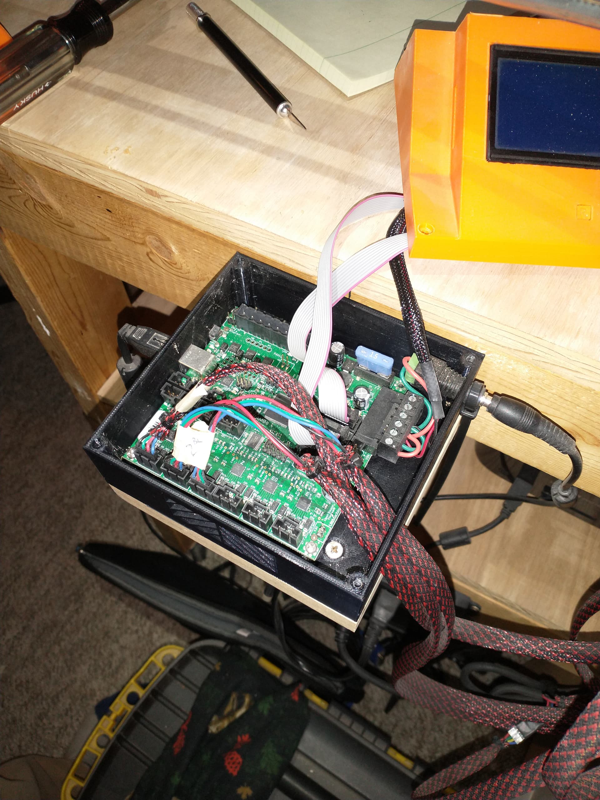
Since I’m using only 2 of the terminals on the limit switch, which of the 3 (+ , - , S) pins do I use on the board?

Once I have it all wired up, do I need to do anything fancy for telling it to home? or can I simply push the home button on Repetier or on the Marlin display screen?

Thanks so much!

At least the dual endstop version requires NC. We usually wire the XY NC and the Z probe on zmin as NO. Confirm things with M119. They won’t stop normal motion, only during homing. M119 will tell you if the endstops are triggered or open (not triggered).

(-), (s). Never (+).

Be careful which axis you home. You don’t want to home Z if you don’t have an endstop prepared.

I have to tell you. There isn’t much point in doing that. The zero is determined by the workpiece, not the machine. So forcing the zero to be in the corner isn’t much help. I don’t use dual endstops. But I also don’t use endstops on my CNC. I just zero the coordinates with G92 before I start the job.

Thanks Jeff!

Lots of good info there for me. I really appreciate it.

Regarding an endstop for the z axis, I plan on designing a “touch plate” that basically is a glorified limit switch, so I can “zero out” the Z axis. But that is later down the road.

Regarding homing the x and y axis, Like a 3d printer, I want it to home so I have a reliable and consistent 0,0 position. I will be pushing the limits of this machine for a bit until I’m able to expand the platform and install longer rails. So I’d like to be consistent in my zeroing.

Could you explain more the wiring and m119 command? I’m still fuzzy on that one.

Thanks!

Ryan sells a little metal spatula in the shop. It works great for this. It has a magnet you attach to the bit and a spatula with a wire on it. When the bit touches the spatula, the controller thinks it hit the limit.

It is your machine (well, your buddy’s :slight_smile: ) and you can do what you want. But unlike a 3D printer, you are subtracting from a workpiece, not adding from a bed. Once you strap in a board, the only position that matters is the position of the board.

You also will need some way to start the machine square. If you are not using dual endstops to autosquare, then you need some kind of hard blocks (I used to use 3D printed ones with my MPCNC) and pull the machine up to those blocks before enabling the motors. After that, they will move in lockstep. If you skip this step, there will not be any repeatability and the squareness will be “to the eye”. Good enough for some text, but not square boxes.

Conveniently, when you enable the motors, the controller assumes that is 0,0. So no need for single endstops. When you install your board and move the bit to the origin, you will reset the 0,0 to that new location. A lot of people coming from 3D printing want to add endstops. But it is not useful on a CNC.

From repetier or cncjs, you can send M119 (always capitalized). The response will include the state of all the endstops. It will say something like:

X: triggered
Y: open

triggered means it thinks the endstop is touching. Open means it think it is not.

You wire a switch with C and NC going to ground and signal (it doesn’t matter which one goes to which). They should show “open” if the switch is not pressed or “triggered” if they are.

The whole thing is pretty fault tolerant. Just don’t ever wire a switch between positive and ground, or you will short the board and you could toast something.

What controller does it have? Can you share a picture of your wiring so we are all on the same page?

I will say that single endstops are useful for just getting the gantry way out of the way. Just home and it sill park over there in the corner. If you ever home after setting up a job it will not save the zero you picked on your board. So that can suck.

For sure. I’m an engineer by trade and have worked with several CNC machines over the years. This is just my first time setting one up and getting it all working how I want.

For sure. I just want a consistent 0,0 that I don’t have to manually move to.

Perfect, thanks!

Absolutely. With this, I’m considering putting the limit switches in the top corner so the gantry’s are completely clear of the work space. Giving me more access to the part on the table.
Do you know what the g-code would look like to have it home in a different corner?

I have the Rambo board with both x motors and both y motors being joined and plugged into the same port (respectively).

That is a good board. It can do dual endstops, which is what I think you want. You’d need to flash it with firmware from MarlinBuilder releases. You can ise platformio if you want to compile it yourself or xloader if you just want to use the .hex we compiled.

If you don’t flash it. Make sure your motors are wired in series. Parallel would look like it worked and then be pretty weak.

You will need to modify the firmware in order to “home” to a different corner. You will either have to change the homing direction or alternately you could enable G38 probing, and then probe to an alternate corner. Probing will require you to enable the following define in configuration_adv.h:

//#define G38_PROBE_TARGET

As for homing, you will need to change the direction of the homing by editing this section in configuration.h (and there may be other changes necessary):

// Direction of endstops when homing; 1=MAX, -1=MIN
// :[-1,1]
#define X_HOME_DIR -1
#define Y_HOME_DIR -1
#define Z_HOME_DIR -1

From a mechanical standpoint, the mounting points for the limit switches assume homing to the minimum corner, so you will need to figure out an alternate mounting on the trucks, or mount them stationary in the corner.

Hmmm, I’m not a fan of modifying firmwares and such. Not my area of comfort.
Maybe i keep the home in the lower left corner and then set a work offset for the top right corner. Then i can send the machine there at the start and end of a program to access the table top.

My take is that 99.99% of all work done on the Primo or Lowrider use an origin relative to the stock, and that origin is in machine coordinates. That is, as part of setting up a job, the router is moved to a corner of the stock and the machine origin is reset using a G92. Once the origin is reset, you don’t have enough information to send your router to any corner of the machine.

There are a couple of things you could do to get around this issue. The first is to set up your machine home/origin to the intersection of a couple of fences mounted on the spoil board. As long as you wanted to use the lower left corner of your stock as the origin of the job, and the fences did not get in the way of your cutting, the home/origin of the machine would also be the home of your job. On this forum, I’ve seen just one machine set up this way.

The second solution is to use workspaces. If you’ve used other CNC machines, you’ve probably used workspaces. They allow you to maintain both a machine origin and a job origin. They do introduce a level of complexity to setting up jobs, and there is a bug in Marlin workspace code that must be worked around. The bug is described in this topic.

Personally, I just disable the steppers (M18), or turn off the electronics, and push the router out of the way.

Alright, I’ve got my x- and y- limit switches in place and wired in.

Problem: when I have them wired to C and NC, i run the M119 command and come back with both triggered while they are not pressed. I can press the switch and it’ll read open.
When I wire them to C and NO, then runn the M119 command, both come back open when not pressed. But when I press, it doesn’t read as triggered.

Also, when I’m making the machine move, pressing the switches does nothing… From my understanding, pressing the limit switches at any point during movement should stop the movement.

Turns out I had wired my switches incorrectly. I can now get the limit switches to read triggered and open as they should be. But they still won’t stop the machine movement when I press them.
Thoughts?

I really need to test things out before posting. limit switches are working fine. I tell it to home either x or y axis, machine moves and stops at the limit switch.

Thank you all for coming to my TED talk.

1 Like

We don’t have it configured this way. Because the firmware is used on machines without endstops too. They are ignored unless you are homing.

Makes sense.

Thanks so much for all the replies and helpful info! I greatly appreciate it!

1 Like