I’ve had my LR3 for over 2 years now and decided it was time to add a laser.
Step 1 was trying to figure out what to get. I eventually settled on a Lasertree K20 Pro. It’s a 20 watt diode laser. It seemed around the right price to performance ratio. I plan on doing some engraving and don’t see myself cutting through anything more than 1/4 inch, if that. I also got some laser glasses and an air assist pump.
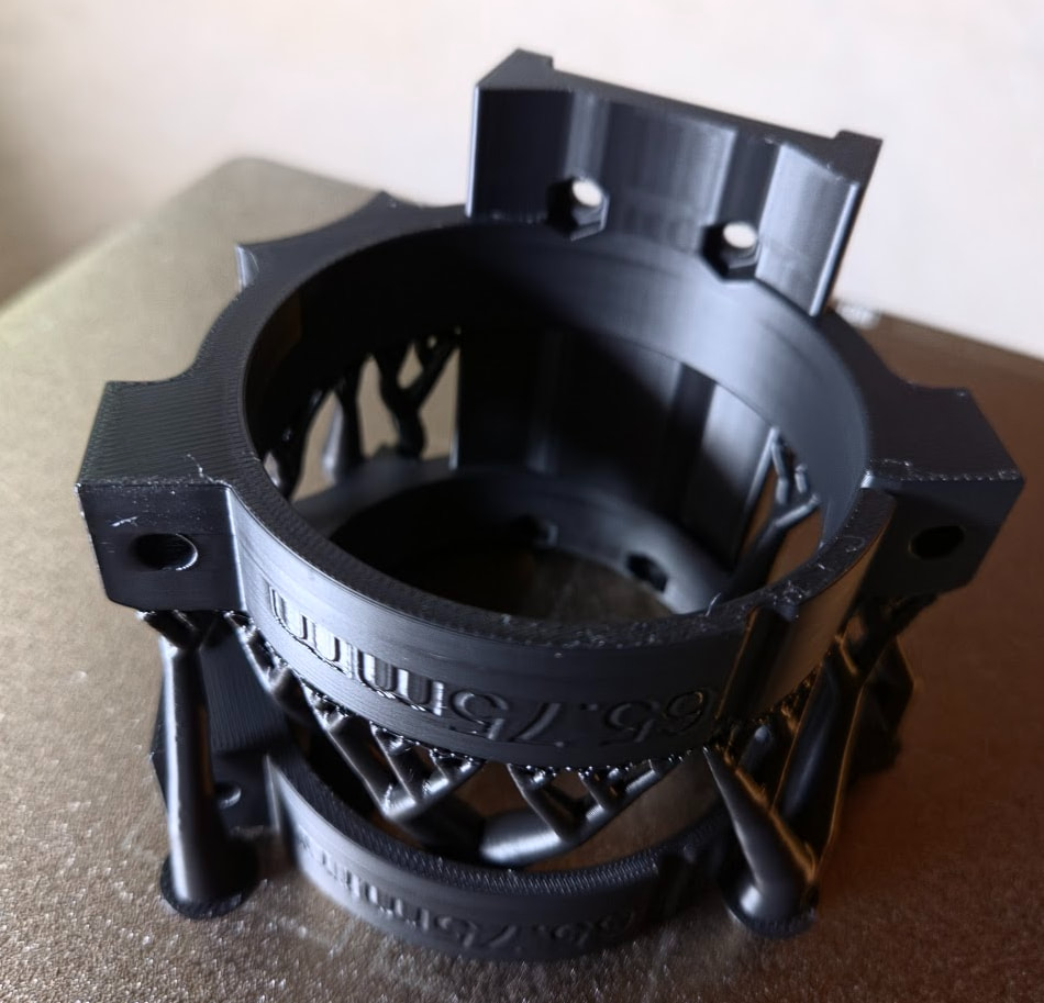
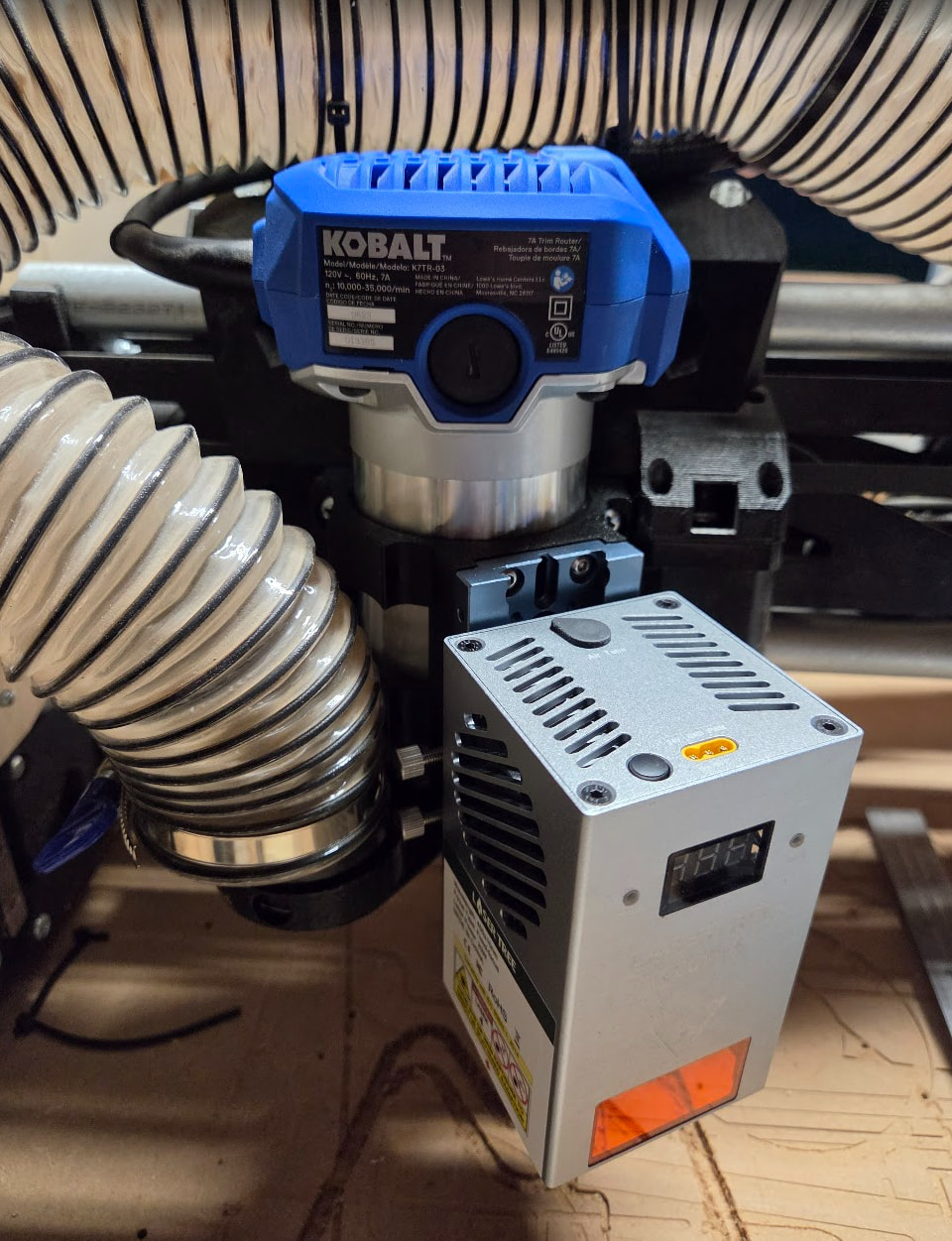
Step 2 was figuring out how to mount the thing. It comes with a nice mounting bracket. After a few failed attempts, my CAD work was successful.
I’m using a Jackpot 1 and the board the laser came with. I have the config.yaml updated. I started a Lightburn trial and am figuring that out. The laser board is connected to pin 27 and ground on the Jackpot. The air assist pump is also plugged into that board as well as the power connector. There’s a 3 pin cable with 24v, ground, and PWM coming out of that board and going to the laser.
My wiring isn’t very pretty, but basically all the mods I’m doing are helping me make decisions for building an LR4. I got my LR3 originally setup based on the yellow brick road, have made some mods, and figure I know enough now to know how far I can detour for the LR4.
A few questions:
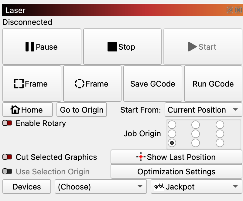
How do I make Lightburn so I can zero at the starting position? It seems to want to use absolute coordinates. I’m so used to zeroing at the project origin. I am exporting gcode and running it that way. I’d rather not need a computer for running a job.
For safety, I’m trying to make sure I understand when the laser would be turned on. As far as I can tell, any G1/G2/G3 command will turn it on based on the S value. G0 or M5 will turn it off.
Does that mean it won’t turn on unless G3 or G4 is set? The config.yaml has the laser set with 0 as the tool_num and I don’t have a spindle, so I think that means it assumes the laser is always active.
I sure you meant to say M3 (full power cut mode) and M4 (engrave, ramp up and down laser signal while moving) and M5 to stop. Yes, that is how it’s working for me.
Right now since I have already had one scare I am also using the tool change command at the end of my program:
T0 M6 - to change to my Autospin so it doesn’t get any bright ideas. My laser is on T10 M6 and put that in my lightburn start command.
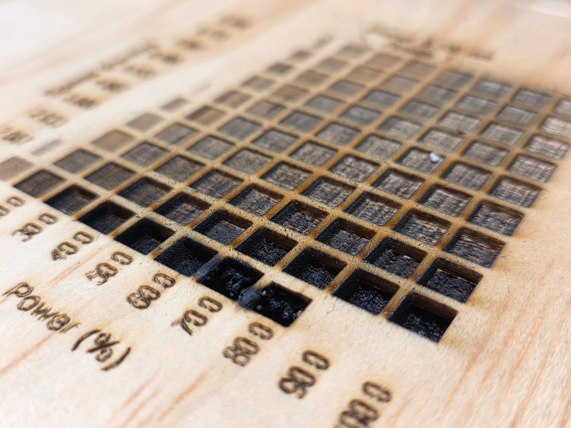
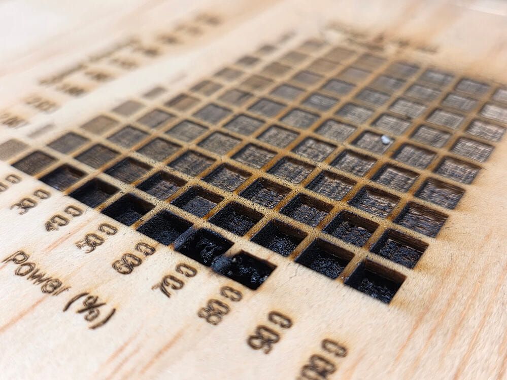
Did an engraving test and killed it at the end because it was going through my 3/16 inch plywood. I’m guessing I should turn the air assist up a bit higher too.
Well done! I just threw a random offcut of 1/2” when I did mine so it made it to the end, but the last hole was pretty deep and a little ashy - and was only at 20W. Have lots to learn!
Also, did you happen to notice on yours if you can read the numbers on the laser while wearing the safety glasses? On mine the letters are blue, and the glasses are pretty darn effective at eliminating any blue so it’s totally invisible
Yeah I noticed that too, it’s pretty amazing. I got the goggles option from your Amazon link and I like them a lot, and it’s already come in handy to have a second pair when one of my family members comes around.
I also connect to my Jackpot with either USB or Wifi. I’ve used gcode on the SD card, but I alway like to frame my project before I run it. My laser is on an MPCNC.
I was out messing with this a bit. I was trying to determine how I could zero things so I could both cut and laser for the same gcode. There are 3 things in play here: router, laser, laser crosshair. I should technically be able to zero for any of them and use either the router or laser for the same positioning.
The answer is this zero script:
; Set active WCS to current position and derive all others
; Activate the appropriate WCS, jog to work origin, then run this
;
; WCS assignments:
;   G54 (P1) = Router bit
;   G55 (P2) = Laser crosshair
;   G56 (P3) = Laser beam
;   G57 (P4) = Pen tip (TBD)
;   G58 (P5) = Drag knife (TBD)

; === Raw measurements - update these with measured values ===
#<_router_to_crosshair_x> = 23.4    ; crosshair X offset from router
#<_router_to_crosshair_y> = -77.7   ; crosshair Y offset from router
#<_crosshair_to_laser_x>  = 14.57   ; laser X offset from crosshair
#<_crosshair_to_laser_y>  = 7.75    ; laser Y offset from crosshair

; === Derived WCS offsets relative to P1 ===
#<_p1_x> = 0
#<_p1_y> = 0
#<_p2_x> = #<_router_to_crosshair_x>
#<_p2_y> = #<_router_to_crosshair_y>
#<_p3_x> = [#<_router_to_crosshair_x> + #<_crosshair_to_laser_x>]
#<_p3_y> = [#<_router_to_crosshair_y> + #<_crosshair_to_laser_y>]
#<_p4_x> = 0       ; Pen tip (TBD)
#<_p4_y> = 0
#<_p5_x> = 0       ; Drag knife (TBD)
#<_p5_y> = 0

; Capture current machine position and active WCS
#<mach_x> = #<_abs_x>
#<mach_y> = #<_abs_y>
#<wcs>     = #5220

; Zero the active WCS here
G10 L2 P#<wcs> X#<mach_x> Y#<mach_y>

; Resolve active WCS offset into act_x/act_y
o100 if [#<wcs> EQ 1]
  #<act_x> = #<_p1_x>
  #<act_y> = #<_p1_y>
o100 elseif [#<wcs> EQ 2]
  #<act_x> = #<_p2_x>
  #<act_y> = #<_p2_y>
o100 elseif [#<wcs> EQ 3]
  #<act_x> = #<_p3_x>
  #<act_y> = #<_p3_y>
o100 elseif [#<wcs> EQ 4]
  #<act_x> = #<_p4_x>
  #<act_y> = #<_p4_y>
o100 elseif [#<wcs> EQ 5]
  #<act_x> = #<_p5_x>
  #<act_y> = #<_p5_y>
o100 endif

; Derive and set all WCS from active tool offset
G10 L2 P1 X[#<mach_x> - #<_p1_x> + #<act_x>] Y[#<mach_y> - #<_p1_y> + #<act_y>]
G10 L2 P2 X[#<mach_x> - #<_p2_x> + #<act_x>] Y[#<mach_y> - #<_p2_y> + #<act_y>]
G10 L2 P3 X[#<mach_x> - #<_p3_x> + #<act_x>] Y[#<mach_y> - #<_p3_y> + #<act_y>]
G10 L2 P4 X[#<mach_x> - #<_p4_x> + #<act_x>] Y[#<mach_y> - #<_p4_y> + #<act_y>]
G10 L2 P5 X[#<mach_x> - #<_p5_x> + #<act_x>] Y[#<mach_y> - #<_p5_y> + #<act_y>]

(print, Zeroed from WCS %d#<wcs> at %.3f#<mach_x> %.3f#<mach_y>)
This is setup such that the router is G54, the laser crosshair is G55, and the laser is G56. So, if you want to zero based on the crosshair, switch to G55, go to the zero position, and run this script. Similarly for the others in their respective WCS.
The result of this is that no matter what I zero in, G54 X0Y0 takes the router to the zero point, G55 X0Y0 takes the crosshair to the zero point, and G56 X0Y0 takes the laser to the zero point.
I got Claude to write that gcode for me with some direction.