I’m working on making my Primo a bit bigger than it started out. I have an idea for a tool or aid to help me make sure the foot placement is near perfect. I had a lot of trouble getting this right in my first build and now that I’m enlarging the Primo, I want to remove the hassle and increase the accuracy. Is this already a thing? Is there a model I can already print or even an easier way? I know I have a tendency to accidentally reinvent the wheel.
The idea:
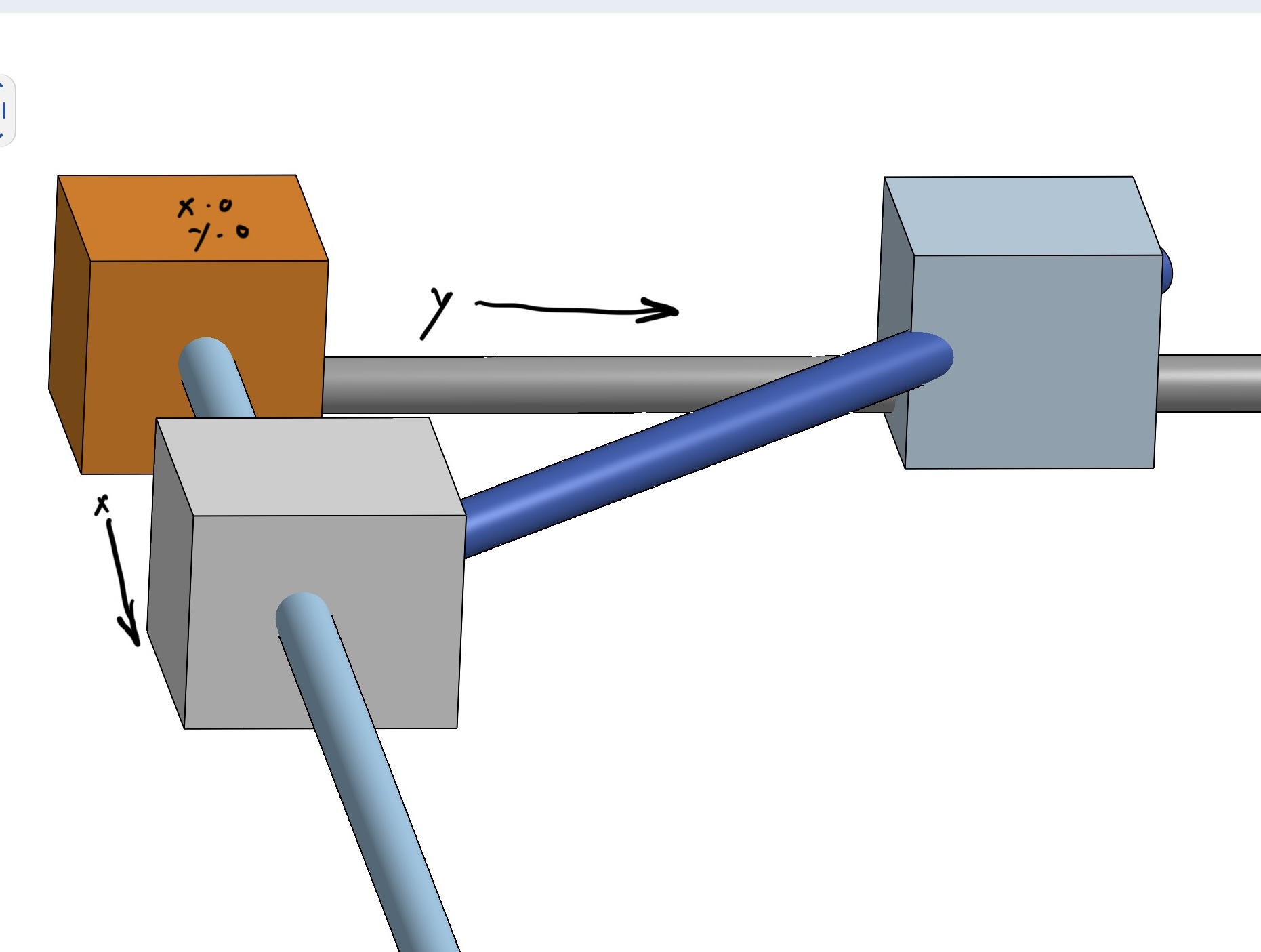
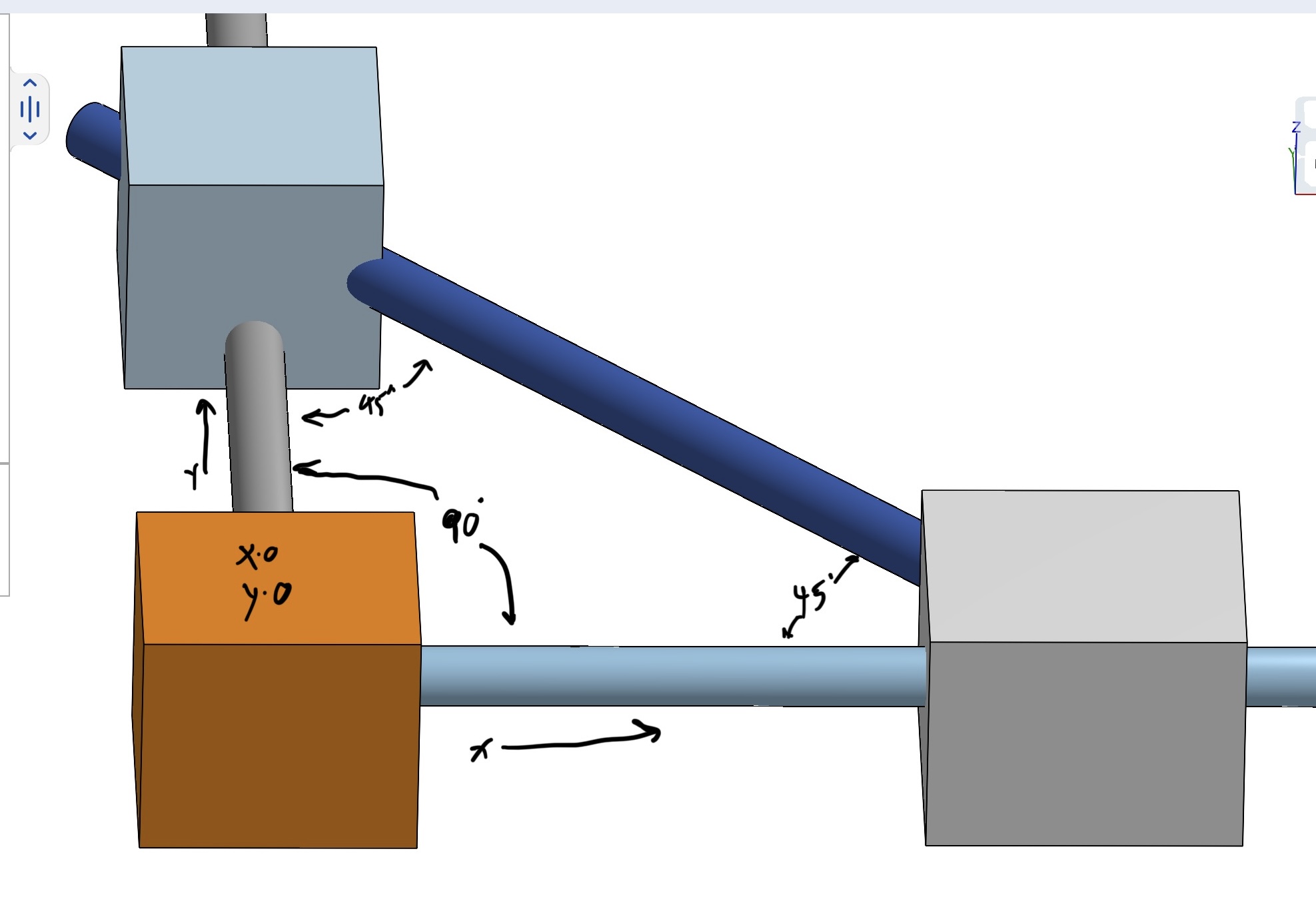
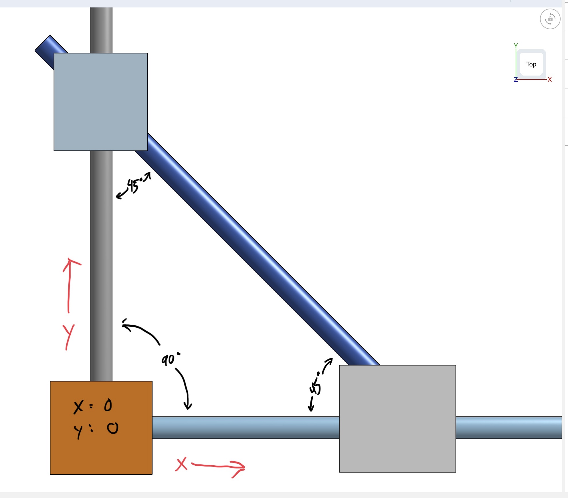
I’d 3d print some parts to hold another piece of conduit in place just for the phase where I’m mounting the feet. I’ve tried to illustrate it here. Thoughts? Point me at a thing that already exists if any? Thanks!
I’m not convinced that this will help much. It will help with right angles, but will still allow a little misalignment, which may result in the sides being not quite parallel. I believe that parallel is more critical than square for the Primo. Square cab be adjusted with the endstops, but parallel is crucial to the machjne motion.
My setup was to use a couple of strips of MDF, which I clamped together, then drilled pilot holes through for the feet. This ensured that the Y length for the feet would be identical for both sides, which in turn means that the X rails will be parallel.
Then I cut pieces that would go between the 2 strips to space the X axis, ensuring that it, too was identical on both ends.
One strip was then glued and screwed to an edge adjacent to a known square corner on the tabletop, and the other set with the spacers aligned to the other edge known square. The result was that the screws formed a good squared footprint. The pieces allow a little adjustment, from which squaring the Primo feet was a cinch. This resulted in corners both square and parallel with minimal effort.