About Steppers: Voltage, Torque, Current, Pulleys and Power Supply

(First of all, sorry to all US guys, but I’m used to metric, is way easier to me :sweat_smile: :rofl: )

I builded up LR2, 3, 4 and MPCNC Primo but never went deep into Steppers topic, I simply stick with default specs, but the LR4 capabilities are to a point where it’s worth spending time to learn thing about it.

I’m using “standard” 59Ncm NEMA17+TMC2209 with 24V power supply, and I always considered the 48W min power supply spec as ok without thinking why. I Realized that it comes from 12[V]*0.8[A]*5[steppers]=48W, but with 24V it has to be doubled, cause the Amps are the same.
So 24[V]*0.8[A]*5 = 96W + 20~30% safety margin = 120W.
Ok, not all the steppers are working at 0.8A at the same time, but the dimensioning have to be done considering worst conditions.

That said, using a stepper calculator I found that at 0.8A the max speed is about 25 rpm, but I can’t really understand why increasing the Amp this value is reduced, maybe someone can explain it to me.

With a 16t Pulley we have:

25[rpm]*32(mm/rotation) = 800mm/min

Than, considering 59Ncm torque applied to the 16t pulley(5,1mm radius):

59[Ncm]/0.51[cm] = ~115[N] = ~ 11.8kg of pulling force.

My conclusion is that we can have about 10kg of pulling force on X axis(the weaker) at a max speed of 800mm/s.

Increasing the pulley to a 20T(6.35mm radius and 40mm/revolution) we can raise the max speed to 1000mm/min but with a pulling force of ~9.5kg, more than the double of what we need(deformation tests have to be done in next days)
So in my opinion we can have better performances with 20T pulleys, considering that the speed we use on ply is between 1000 and 2000 mm/s.

Now the missing part to me: how can we calculate the max torque at a given speed and given Amps?
Cause torque curve is made with 2.2A.
1 Like

I can’t do a proper job of this as I have to run, but your math is wrong, as is your understanding of stepper drive methodology.

That’s exactly the answer I need, It’s not easy to figure it out but I want to understand. No rush, if You can explain me how it works when You’ll have time would be great

1 Like

Today i have tested at what load the axis lose steps. At 1000mm/min with 0.8A happened around 4kg, with 1.2A at about 5kg… so I understood my math was wrong😂

1 Like

I’m doubtful that you are running at 60000 to 120000 mm/min, but if you are, that is pretty amazing! :upside_down_face:

The drivers are constant current, not constant voltage. They work a lot different than 90% of power supplies you are used to (which are constant voltage).

The power supply is constant voltage, and will supply a variable amount of current. When the current needed to keep 24VDC out exceeds what the power supply is capable of, it will overheat or reduce the voltage.

But the drivers provide constant current. Let’s start with a stationary motor and just one coil. The stepper driver will want to provide 0.8A through that coil. To do that, it will apply the 24VDC to the coil and turn it on and off until the stepper coil has 0.8A going through it. The 24V may only be connected to the coil 10% of the time.

As the driver wants to move the stepper, it will move how much current is going into coil A, coil B and reverse the direction of the current to get smooth motion. At any microstep, it is basically applying a total of 0.8A across the coils in total.

But also, as the stepper moves, it is moving through a varying magnetic field. That causes a backflow of current, which can also be modeled as a reverse voltage or increased impedance (resistance). So instead of applying 24V 10% of the time, it might be applying effectively 12V for 20% of the time.

There is also a loss of voltage in the wires and coils leading to the stepper motor. So some of those calculations are going to be machine dependent.

In the end, if you are moving very fast, the power supply may be attached to the coil 100% of the time. At that point, the power supply is saturated. Above that saturation limit, the current will not be at the max 0.8A anymore, and the holding torque will be reduced. When the external torque (from the force of the bit moving through the material) exceeds the holding torque of the motors, the motors will skip. This torque is almost proportional to current. So it doesn’t go to zero right away. Even above the saturation limit, it will still have some holding torque.

That 59Ncm is the max rating for the motor. The max current for the motor is probably 2A. At that current, the drivers and the motor will be too hot, and we never set the current limit that high.

More likely, you’re seeing skipped steps in your tests because you are applying 0.8A. I would guess that is proportional, so 59Ncm*0.8A/2.0A = 24Ncm. That’s what I would guess the limit is when standing still, and it should be pretty similar when moving. It is difficult to test because acceleration has higher forces and there is friction to contend with.

This might be the case in the rare situation where every driver was moving at a speed above the saturation limit (rpms) for each motor. In that situation, each driver would be connecting the power supply 24V directly to the motors 100% of the time.

Outside of that saturation, if you want to compute the power, you need to include the duty cycle. If the motor at rest needs 10% duty cycle, then the effective voltage is 2.4V, not 24V. 2.4V * 0.8A * 5 = 9.6W. The 10% number is coming from nowhere though.

7 Likes

:rofl: I’m using Rockets instead of steppers

2 Likes

Thank you, You were very clear!
Now another doubt arises in me: the Holding Amps are set to 0.5 instead of 0.8, but when the machine is moving along a single axis, for example X, the Y axis is withstanding the side force of the cut only with 0.5A?

That is a software decision in FluidNC. I am not sure what conditions need to be met to switch from run amps to hold amps. My guess is that it needs to be in idle to switch.

Is it?

I thought this was done automatically in the driver anytime it wasn’t in motion.

That’s what I gathered when looking into it for my 3D printer as to why Klipper suggests keeping hold current and run current the same.

The explanation was that it automatically switched between run and hold, and that switch could cause print artifacts due to vibrations, etc.

A quick scan in the FluidNC code looks like it passes both configurations into the Trinamic driver, and just lets it manage it.

But I might be too far out of my knowledge area…

4 Likes

Yeah, it’s a function of the TMC2209.

Section 9 of the datasheet.

There appears to be a few key parameters.
I(run) - Normal running current
I(hold) - Current in ‘stand still’ mode
T(powerdown) - Time between normal running and stand still, set in increments of 2^18 clock cycles which is 16.4ms on a 16MHz clock. Max setting is 4.2 seconds with a 16MHz clock.
T(Iholddelay) - Time for the ramp between normal and hold current once the power down delay has elapsed. Set in increments of 2^18 clock cycles with a max of 15 so ~250ms max on a 16MHz clock.

3 Likes

That’s an interesting consideration. I don’t think it’d be much of an issue because the holding torque at a given current is much higher than the torque at speed. There’s also the situation that you only need the torque capability to be above the torque demand instantaneously for any given situation. That torque demand is only partially going to be cutting torque, it’s also going to have components for acceleration and drag losses.

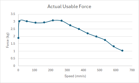
I took a look around and found a roughly equivalent stepper at StepperOnline that had a torque curve listed. It’s 55N.cm at 2A. I extracted the torque curve from the document provided and converted it to actual usable torque, assuming 0.8A running torque, 0.5A holding torque and a 16T/32mm circumference GT2 pulley:

image

My assumption was that the torque fall-off of the motor was going to mean that the crossover point between the holding torque at lowered-current and the lowered torque as speed increases would be at a relatively low speed. As it stands, it’s a fair old way out there.

I still really like the idea of the stand-still torque being set lower to reduce motor heating but I don’t see it being logical for them to be so far apart. I personally wouldn’t change anything unless I were seeing issues, but I’d probably either bump the hold current up first if I saw issues or the run current down if things were warm and I wasn’t seeing issues.

The ideal situation would be to have the controller change the holding current to be the same as the run current while a job was in action and then lower it once the job had completed but even then that might cause an issue where you only see overheating issues during a long cutting job, rather than being able to test it while it’s just sitting doing nothing.

1 Like

This looks like the torque curve that I was basing the 500 RPM number off of.

Correction on the pulley, we use a 16T pulley with a 32mm run on GT2 belts, not a 32T pulley.

2 Likes

Good spotting, I used a 16T pulley in the calculations and then meant 32mm circumference. I’ll edit.

1 Like

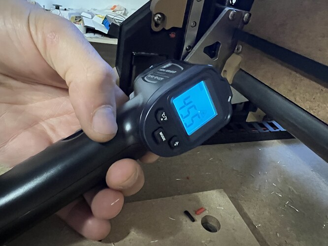
This is kinda cool. I was testing new configs earlier, and I could see the step down from .8 to .5 on the thermal camera. The drivers move heat pretty fast.
I changed the new config to be 0.8 and 0.7. I will hit them with the camera tomorrow to see if the difference is noticeable. I get the feeling some issues were from that step down being to low. 0.6A or 0.65a might be better. I see no reason to slam them with heat if we don’t need to.

1 Like

The more I think about it, the more I can’t see a reason to do the step-down in current in the drivers. They’re simply not configurable enough nor have enough information about the operation of the system to do it in a smart fashion. Given the speeds that most people will be cutting at I suspect there are a lot of scenarios that will see the drivers go into hold current mode. Cutting at 10mm/s, any straight cut along a single axis of ~50mm will see them drop back to hold current.

Compared to the situation where someone may have a job full of curves that may run for an hour and never see the drop down to hold current, that situation will see peak temperatures that may never otherwise be seen.

That seems like 2 traps that are being set for people with unnecessary variability, in both cases potentially only becoming issues as jobs get larger and more complex.

My approach would be to disable the hold current (or set it to the same as the run current) and then adjust that to a point where I was happy for it to run long term, much like already happens on the other non-UART configured drivers.

The temperatures that we’re running these things at in order to preserve the PLA parts aren’t remotely hot enough to worry anything and if the drivers are overheating, I’d rather know that sooner rather than later.

4 Likes

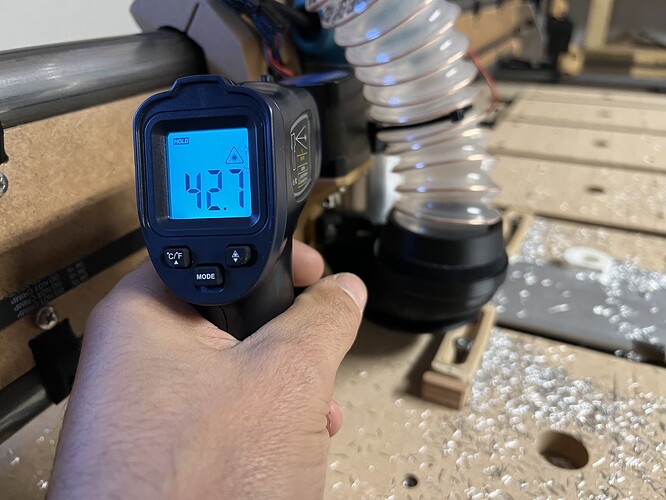
Measured during aluminum trochoidal milling, with Run Current at 1.2A
(Reflection settings have to be check)


We aren’t even traveling at 200mm/s. So this effect doesn’t bother us, right?

Ah, right. So I agree that it doesn’t make sense to have a lower hold amps. Unless you have a lot of friction.

Slap a piece of masking tape on there. Unless your shop is very very cold that is not the correct temp. Steppers are usually shown as temp over ambient so the scale does move but there is no way my steppers are that cold at 1.2A. In the summer, mine sit at ~45C at 0.8A

I’ve never had an issue with tool changes but I know some avoid it because of losing position. I wonder if increasing the hold amps would resolve that.

Hmm, on the Jackpot it might be possible to change the hold amps in gcode. So, increase at the start of a job and set back at the end. You can do this with single commands but I’m not sure if they take effect without a restart.

2 Likes