I suspect there are electrical engineer types on these boards so I thought this would be as good a place as any to get some help. I bought some 3-pin/2 position switches for the main power for the control board. It wired in fine with the positive from the AC/DC brick to the middle pin and a wire from the correct outer pin to the 24V input of the control board, and the negative wire from the brick to the negative post on the board. Simple enough and that works fine to turn on or off the board and fan. The problem is I would like the LED on the switch to power on when the switch is in the ON position, but it doesn’t light when ON and I can’t figure out which wire from where should go to the second outer pin - assuming that’s what I need to do and the switch isn’t defective. I tried a wire from there to ground but that did nothing.
Any electrical insights from someone who knows how this should work will probably save me from frying my board, so thanks in advance.
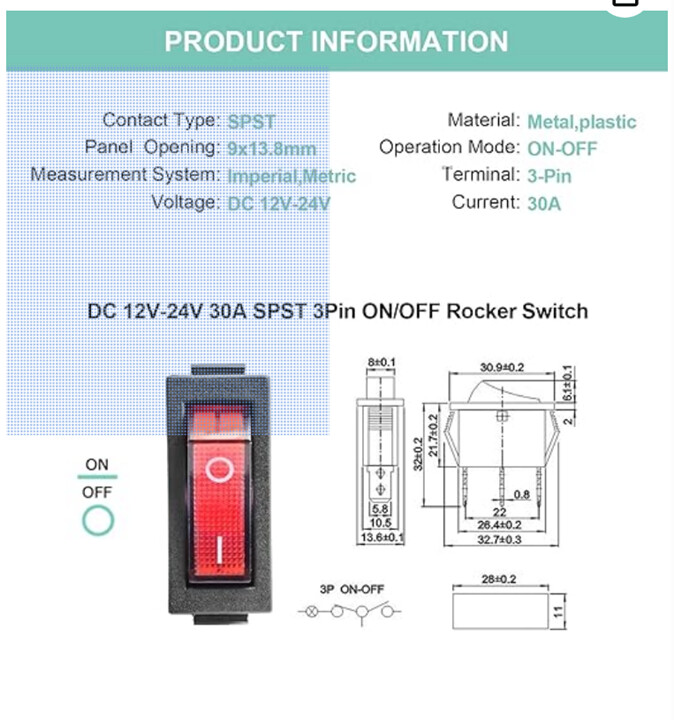
Amazon listings often omit stuff like correct diagrams. It’s frustrating.
If you measure conductivity from terminal to terminal in both on and off positions.
1 pair will be 0/infinite. This is power in/out.
1 pair will have constant conductivity, but diode polarized.
The remaining pair is switched but polarized.
If you put power and ground to the switched polarized pair, the LED will light whenever there is power, regardless of switch position. Useful for showing where the switch is and master power status. Load (board) then goes to the other side of the switch.
If you put power and load the other way around, the light will switch on and off with the board.
Some switches operate this way switching ground, not power. You can tell with your multimeter continuity tester.
The switches of that type that I use switch A/C power, but work the samw way. Live in/out and a neutral connection for the light.
Edit: from the diagram there I think that for what you want, you want power in from the brick at one side, and out to the board in the middle, with ground at the other side. It looks like the center pin and one side is always connected to the lamp.
Thanks. Still a little confused, because the diagram you posted implies (to me) they want the positive line from the brick to the center and the load (to the control board) from the silver end. That’s how I soldered my switch. I then ran a ground wire from the gold terminal to the negative post on the board, where the ground from the brick is also connected.
I have 5 of these and I can get it to work (light on when the switch is on - my preference) when I run a positive from another brick to the center and the negative to the gold post - I think that’s exactly what I set up on my control board/brick. Unless I’m really confused, I suspect the switch might be bad.
Thanks for the video, but that exactly how I have it wired, but the LED won’t light (the board works fine).
I discovered the problem, but now I’m not sure how to proceed. If I use a different power brick that I have around for testing, I can connect the leads to the middle and gold post and the led lights. This works with the brick leads in either orientation on those two posts. However, if I connect the V1e brick’s leads to the same posts, it only work with the red lead connected to the gold post and the black lead to the middle post. That’s opposite of what every resource I’ve researched indicates, including the limited schematic from the Amazon listing (where the “hot” lead goes to the center and the negative/black lead goes to the gold post).
All 5 switches in the set I bought work the same way. Are the diodes in all of them backwards? I tested the brick leads and they are correct. In any case, since the switches worked to power the board with the red brick lead to the center post, the black lead to the outer silver post and the load (the board) from the outer silver post, and the board worked with red and black directly from the brick to the board’s 9-24V input posts (as “+” an “-”, respectively) before I tried installing a switch, which post should I run the load line from the board to. Is the center post now the return negative from the board?
I’ve never had so much trouble with what should be a simple switch.
Mine (And every one that looks liek that that I can get here) are lit with 120 or 240VAC, not DC. That does seem to be what hte listing you linked was, but the only ones that I see are for mains AC wiring. Maybe yours is mislisted?
You can also see if the LED is reversed.
It appears to me from the diagram that the center pin is connected to the copper pin through the light all of the time. Take one of your spares, and try your DC voltage through it with ground at the center and voltage to the copper, and the other way.
Failing that but carefully you can try running the AC voltage through the lamp. This will result in a big “pop” if that really is set up for a small DC voltage, but if it’s set up for AC, it will light.
I use a couple of those for things. Some, I want the switch to have light all of the time, and some I want the switch as a power on indicator. Wiring with the power and load reversed will make the light work different ways. Power to center lights the lamp all the time. Load to center only lights the lamp when the switch is on.
Thanks. The Amazon listing indicates the switches are “only for 12-24V DC”, and they light up properly when I use a spare 9V brick wired to the center and gold posts in either orientation. Given that 9V lights up the LED, I’m hesitant to try wiring the switch to mains. The V1e brick only lights up the the LED (when the switch is “on”) when the red lead is wired to the gold post and the black lead to the center. No other combination of posts and leads will light up the LED and no combination leaves the LED light on independent of the switch position (i.e. I can’t get always-on).
I think I’m going to call it a day and re-wire the switch the way I originally had it (hot to center, load to silver post ad neutral to gold), and forget the LED light. The only other option I see is to risk blowing up the board by wiring power to the gold, neutral to center and hope for the best when I connect it to the board -somehow.
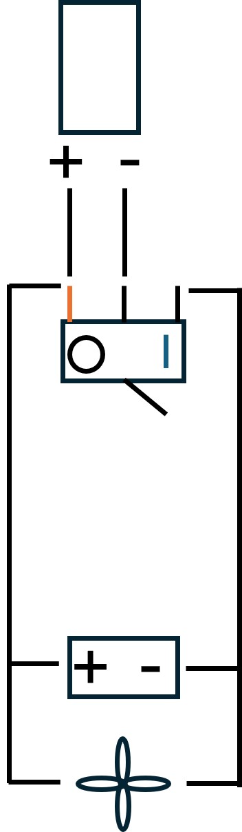
Thanks everyone for the suggestions and advice. I figured out a wiring scheme that turns on the light when the power is on. It seems to me to be very different from what was implied by the Amazon wiring instructions, but that was confusing so who knows what was meant. In any case, the key was wiring the power from the brick to the gold post, not the center, and the negative from the brick to the center post. Neutrals from the loads go to the outer silver post.
If anyone else has trouble with this type of switch, here’s the wiring diagram for what I ended up with. The +/- box symbol at the bottom is the 9-24V input block on the Jackpot control board. A fan is after that.