I’ve completed the build and initial wiring of my LR3. I have a Jackpot board. Using FluidNC, I can move in any direction. So far, so good.
However, I’m not clear on how to:
Enable the endstops. Using the LEDs on the board, I can see that the switches are working, but they don’t seem to be doing the job of limiting motion. Is there a setting I’m missing?
Since both Y (rail) axis endstop switches are facing the same forward direction, how is the limit of travel set for the reverse direction?
From what I can read, it seems that to update the configuration, you edit the YAML file and place it in the root of the SD card and restart the Jackpot board. Is this correct?
And, finally (I’ve save the newbiest question for last), how are the extents of the x, y and z motion set? In Marlin (for 3D printers) there are settings for each of these, I missing how this is determined in Fluid.
Thanks in advance.
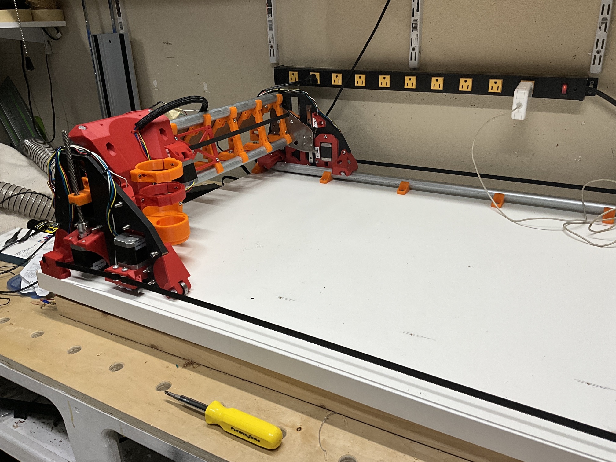
I’ve added a photo of my build. The substrate is an IKEA desk panel that is mounted via hinges to the wall. When not in use, I loosen the y tension, pull out the belts and store the LR3 elsewhere. My workspace is a garage which serves home storage, my woodworking workshop and budding metalworking shop. Space is at a premium!
Endstops only work during homing. They will do nothing when you are just jogging around
Know the size of your table and don’t set a job to run outside of that.
Depends on what you are needing to update. Once you get your machine all trammed and square you can make those changes in the webui and save it to your config file. To update the firmware its best to save a copy of your config somewhere else. Then you can upload the new firmware. After that you can load your config file back on the machine and have all of your pull offs set correctly
We dont set soft stops. Doing that messes with things because of the way we zero for each job.
My experience is with 3D printers and I guess I have a skewed view of things in CNC world.
I have it now, all it took was realizing that what I thought was Y zero was in fact Y max.
I’ve got my endstops working when I home, I have a rough tram in place and I’ve completed a dry run of the crown (I have to make a touch plate and implement the macro to zero the Z axis).
The default V1E config file does not know the size of your table, and it has hard limits disabled and soft limits disabled. You can input the dimensions of the cutting area of your table, into your config file, and there you can also enable hard limits and soft limits. Hard limits will prevent the machine from jogging past an end stop. Soft limits will prevent from jogging past the travel distance of your table in a given axis direction, both ways, in each axis where it is enabled. Please note this is something that is an attribute of each axis, it needs to be set for each one.
Thanks, I’ve set the Max Travel for each of my axes based upon physical measurements of my LR3 and the work area.
I am using your Probe macro (unedited). I’m having trouble with the crown.g file in that it doesn’t seem to be responding to the probing. I ran the probe and then the crown file but the LR3 rises up about 40mm from the working surface and draws in the air.
I set my Z max travel at 65 mm and I noticed that in the G32 command in your script, you specified 80mm of travel. Should I change the value?
Also regarding the G32 command, I’m guessing that any .g job will work from the offset determined. Is that correct?
Again, thanks for your help, I really appreciate it.
My LowRider has “Dan’s extra tall YZ plates” ( @SupraGuy ), so I have more Z travel than normal LowRiders. The script would likely need edited in two ways: The travel distance would likely need edited if the LowRider is “normal” height, and the touch plate thickness would need edited to match your own.
Yes, for the exact reason I explained above.
Yes, assuming you stay in the same workspace (which is a segmented storage of origin coordinate values), the origin (set of zero values) should apply to all jobs cut within that same workspace.
Below, I am echoing two replies I made on YouTube in response to your questions there:
Regarding the concept of a global var or param, there is a whole array of coordinate values that are stored in any board running either GRBL or FluidNC, regarding not only the “machine” origin for each axis, but also for multiple “workspace” origins for each axis. The Zeroing process sets one of these, depending on how you program it. Please watch this super helpful video that explains the various workspaces:
The FluidNC wiki has a nice helpful section on probing. Notice the subsections on “Using the probe” and “Setting Work Zero” and especially “Optional P parameter” which is what I use in my script, and it not only sets the zero but does so to accommodate for the touch plate’s thickness. http://wiki.fluidnc.com/en/config/probe
Also note: a more accepted practice for probing, would be to manually jog / move the bit closer to the material and then use a probing script that has a shorter target distance. I just tend to like homing to the very top, and then probing to the very bottom, without trying to do manual jogs in between the two.
Quick question. I’m also planning to implement your dust extraction mods using your parts for the DeWalt router. Is the universal pen holder compatible with the revised router mounts that are part of the dust collector modification?
By the way, your contributions to the Low Rider community are outstanding along with your unflagging support of its members. Thanks so much!