Would the order you do the commands in matter? Invert the axis before setting the home position or vice versa.
These values just appear to be setting flags, so it doesn’t matter in what order you set them.
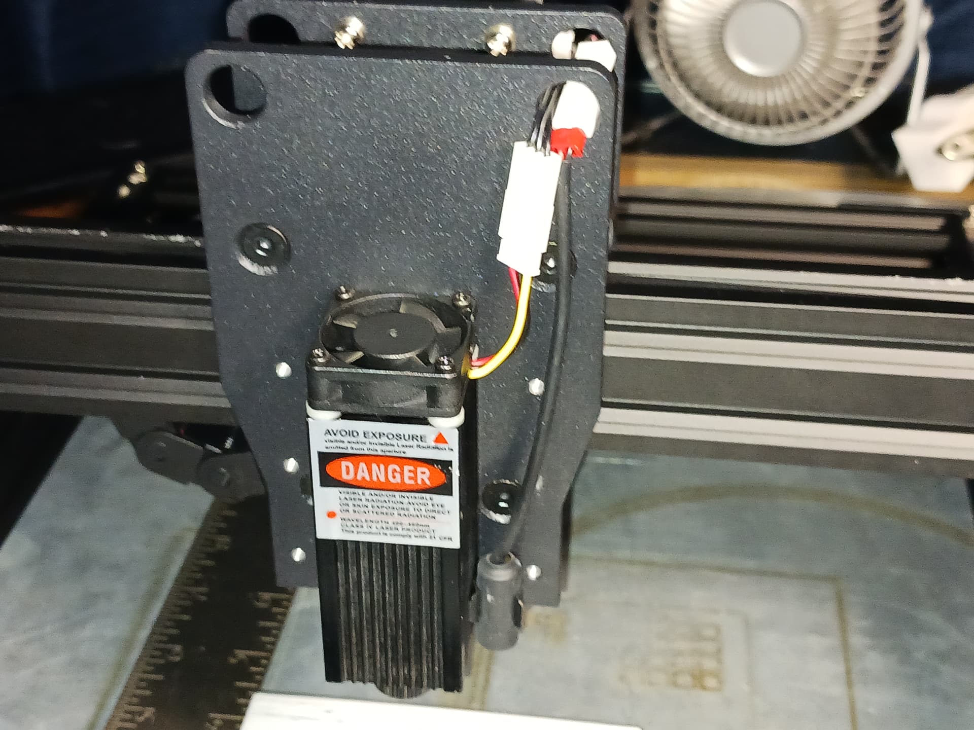
As many/most of you know I bought two of these machines… and I’m now setting up the second one. All is going well… flashing and configuring GRBL, wiring mods for different laser, etc. One thing I’m doing different, however, is adding a newer, thinner, Z-lift to minimize futher reduction of an already small workarea.
This machine really presents a nice big, flat, metal, carriage plate to work with and enough convenient pre-drilled/threaded holes to make it a “snap” to bolt stuff on…
Removing the included laser and red cross-LED module, I used Onshape to create and set up a relatively thin three-piece dovetail slide using the 3-hole “stack” down each side…
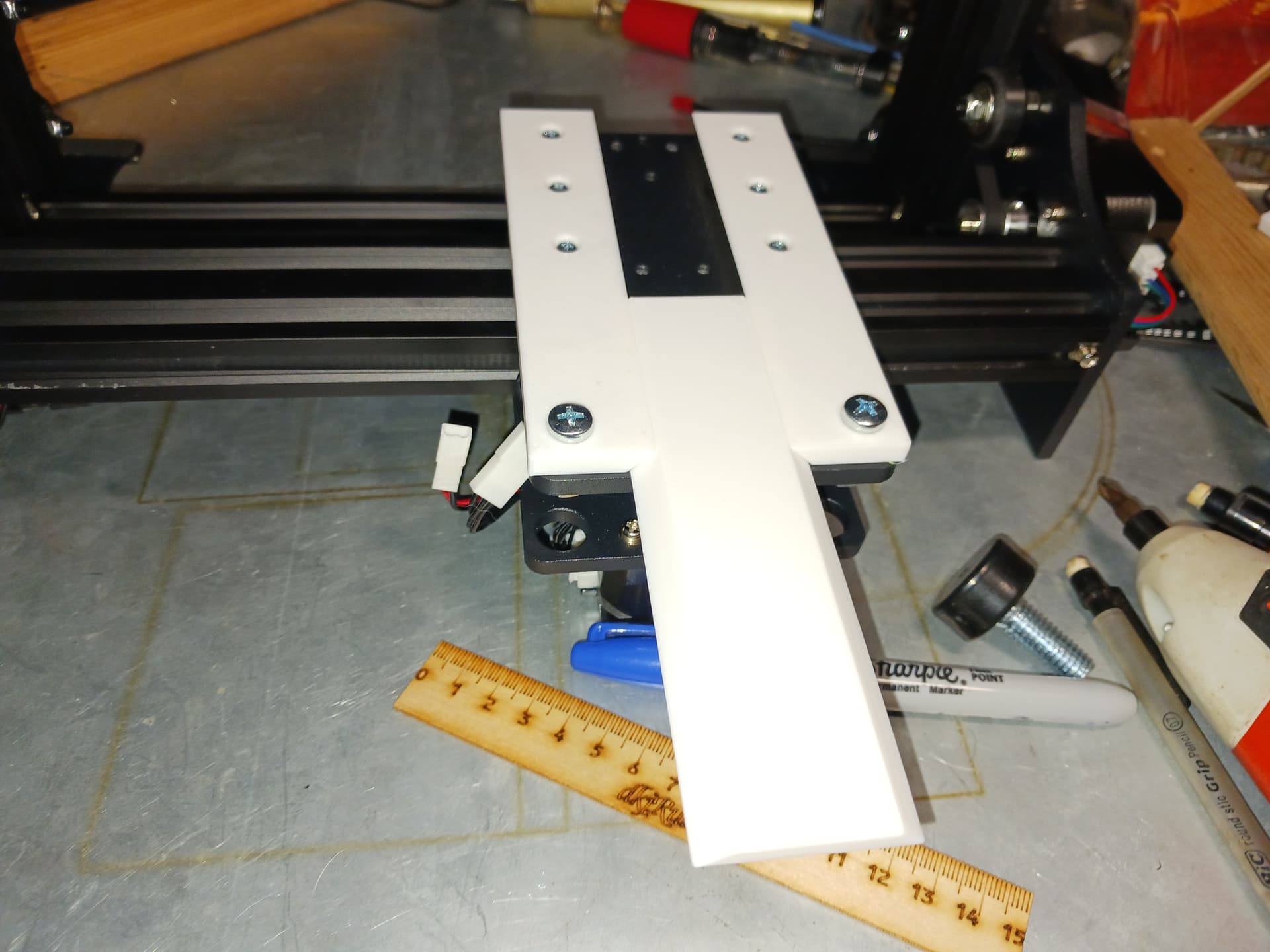
The central slide provides ample room for different laser module hole patterns. But I’ve got several Neje laser modules that came with a high quality metal clamping mechanism so I just added holes to mount one…

Setting the laser on it’s feet a simple clamp holds things quite securely for testing…
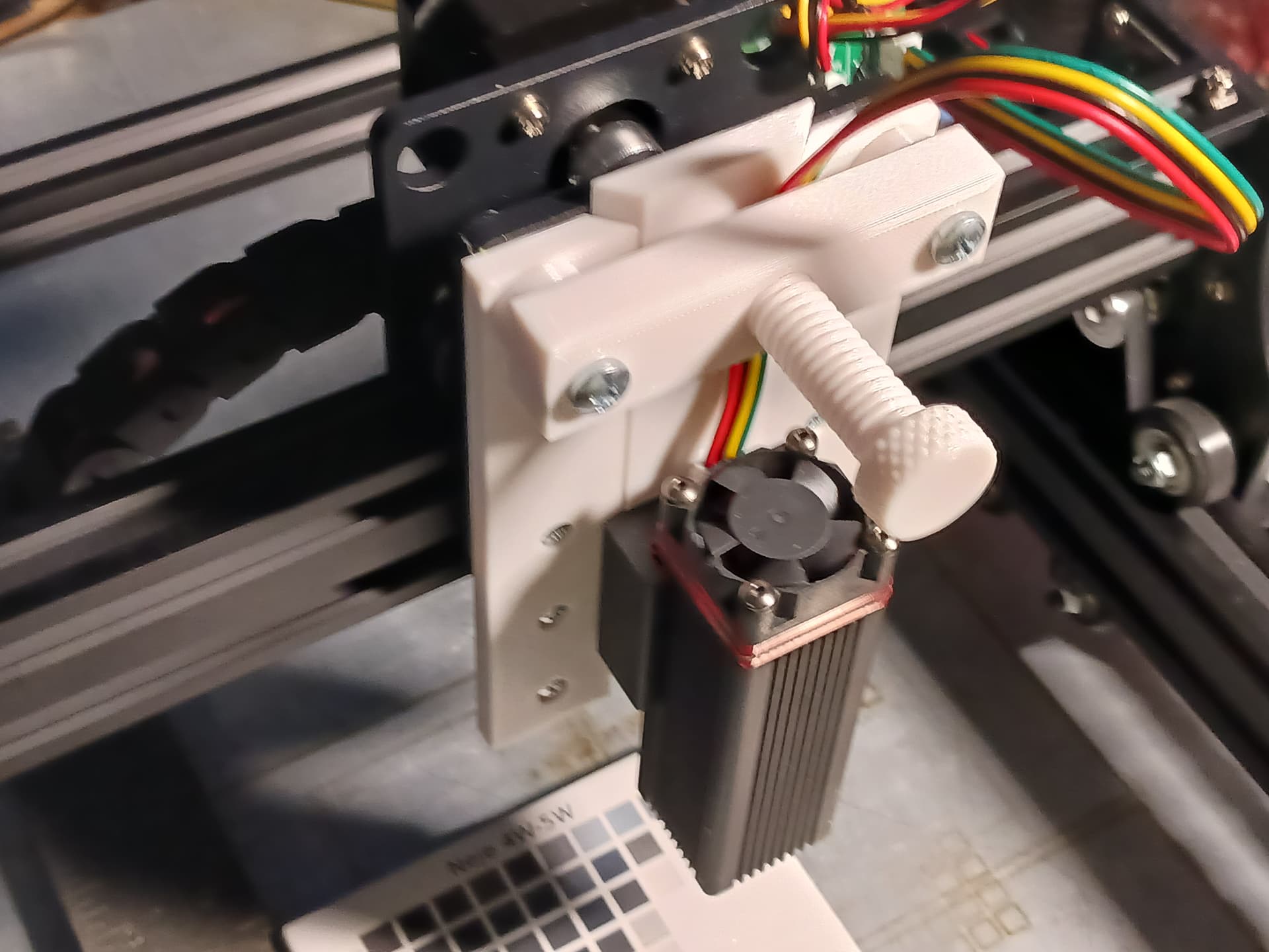
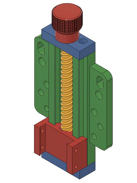
Noting the two large holes at top, I envisioned a bar with threaded bolt through it to clamp the slide in place. I found a printed C-clamp and a knurled thumbscrew out on Printables… and then used TinkerCad to cut, stretch, combine, and add the bits I needed to make a suitable clamp mechanism…
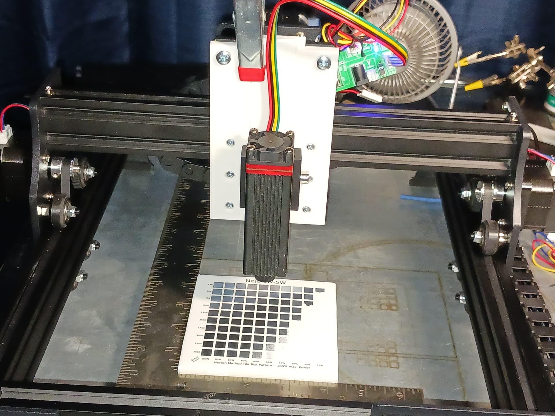
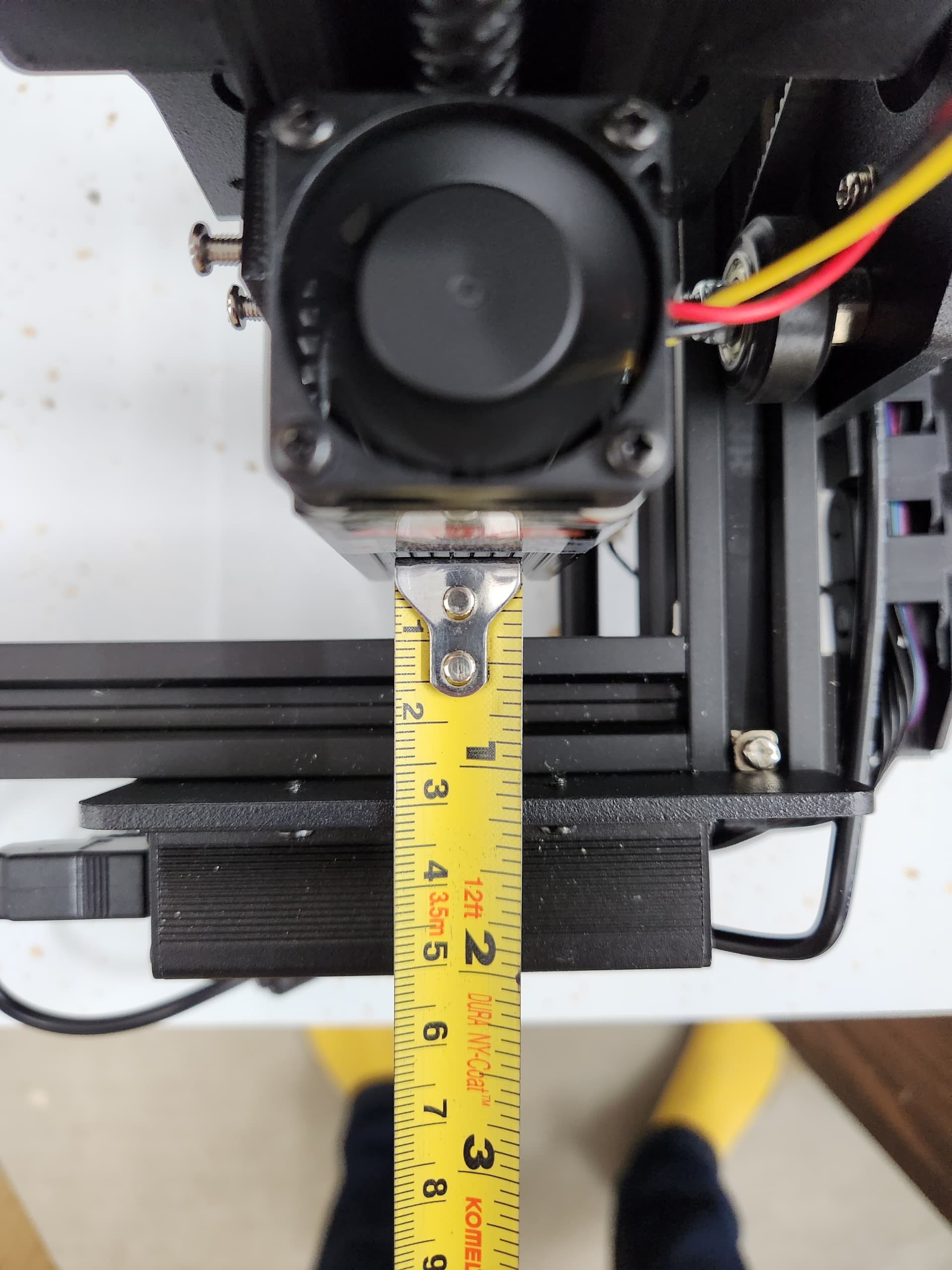
I’ll probably need to lengthen the central slide to insure I have enough “reach” to get down to the work surface but otherwise all this seems very workable. I usually set all my lasers to focus at 50mm below the bottom edge of the laser housing, so using a 50mm gauge block I can easily set the focus for varying material thickness…

I’ll put it out on Printables when I get the time and energy. Wow, so busy I am 

But right now… I think it’s time for my nap. 
– David
5 Likes
Not being able to leave well enough alone, I decided to redraw @dkj4linux design in fusion 360 so I can adjust it some. It is supposed to be here tomorrow, so will wait until then to adjust the design any. I will print a couple of test prints first to see if tolerances work for me. Here is what I have so far. I used the coil in fusion 360 to make the leadscrew. Think I have the assembly correctly.
2 Likes
Now we’re talking!

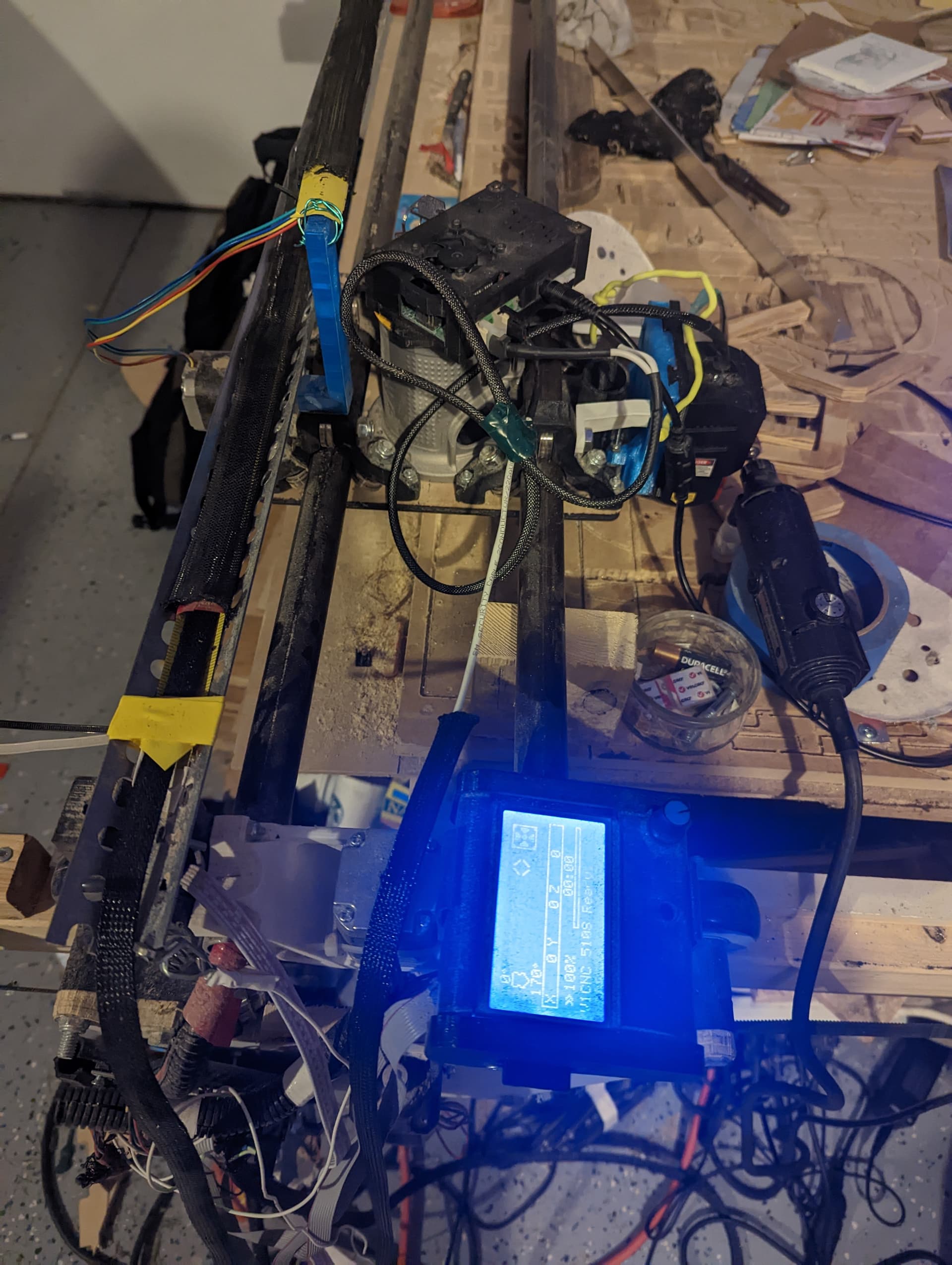
Lowrider v2 setup that barely makes recognizable pictures (but does good wood work). Think it’s loose laser holding and definitely a touchy connection.
The new setup.

Much cleaner wiring and setup as well as good looking pictures lol. Got a raspberry pi cncjs on WiFi flashed so hoping to try that out next week so I don’t rely on Windows sending my gcode.
Thanks for the recommendation @dkj4linux
2 Likes
I put “Another Z-lift mechanism for $79 Cenoz JL1 laser engraver from Amazon” on Printables for those interested. – David
4 Likes
I think I’ll be keeping the screw lift for now. Losing 20mm in the Y axis isn’t that big of deal for me.
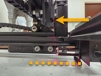
As I mentioned before, here is what I ended up doing to move the Y axis to make room for the original Z lift mechanism added thickness. I just increased the screw and spacer length for the limit switch by 20mm.

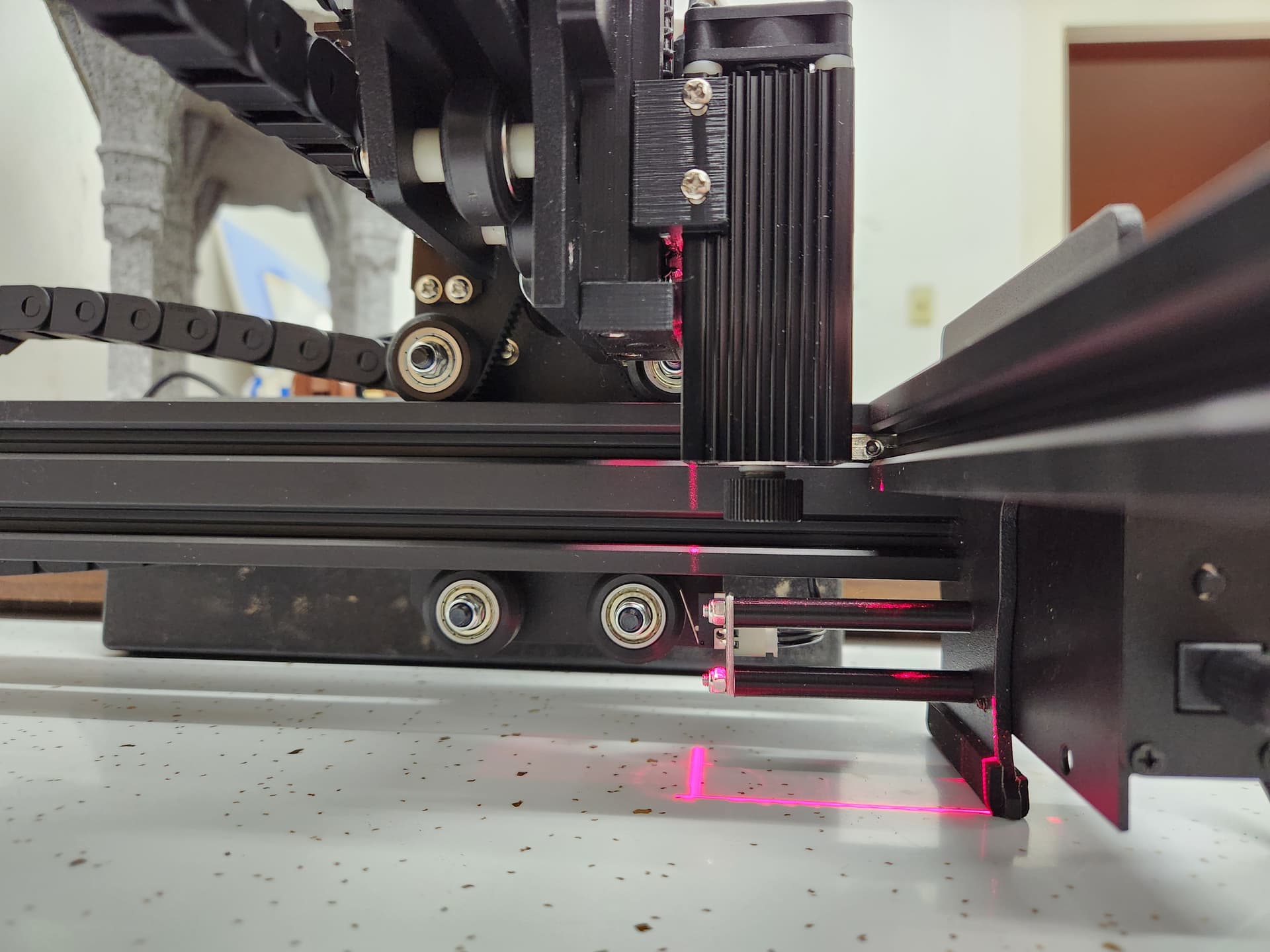
I could probably reduce the spacer a little to bring it a closer but I think I’m going to keep that gap because I want to make a shroud thing ,like the one below, to add some extra protection from the laser since it’s not in an enclosure.

Also, I found out the X axis is actually 220mm not 200mm. So I now have a engraving area of 220 x 270. Good enough for an $80 machine.
4 Likes
Well, they shipped me the JL2 cantilever version & not the JL1 version, so mine will be going back. The photo on my order page shows the correct one, so I know I ordered the right one. On another note, I see the cantilever version is now $59.39
I tried the @Bigburlybug parameter.
It would home to the corner where the limit switch are, but Y moves the opposite that I would expect / want. As much as I don’t “need” homing, it is bugging me to the point that I messed with it again last night while I was letting some paint dry.
I moved the Y limit switch to the opposite rail (actually installed a new one so I could easily revert by swapping which one is plugged in and I still couldn’t get my directions the way I wanted them without the automatically triggered overtravel. I even tried electrically switching the direction of the Y motors by reversing a coil wire pair to no avail, so I went back to developing a “homing macro”.
LaserGRBL let me put $ system commands in a code sequence that I could save off as a “button”. However, there seems to be something about GRBL that gives a higher priority to system commands and doesn’t make them sit in a buffer waiting for movement commands to finish. Consequently I couldn’t get a unary macro to do what I want, but breaking it up into two works fine.
- The first one adjusts the steps/mm down and then calls the homing sequence $H.
$101=50
$H
G92 Y-110 ; this gets applied relative to the 360 offset built into the firmware such that Ymax = 250 - The second one restores the correct steps/mm and then sets the G92 offset to the right value so that the front right corner is Y-Min, X-Max (0, 220).
$101=80
G92 X220
So, its two clicks and no typing if I decide I need it.
This technique doesn’t work in UGS. I’ll give it a whirl in Lightburn at some point.
The remixed laser holder for the screw version of the z-lift does fit better for me than the original, but I will probably print David’s latest slim version just to try it out anyway. One thing my son pointed out on the screw drive one is that if you set the focus nominally at the plane the machine sits on with the lift mechanism all the way down, you can set the focus for a work object by setting the gap with a scrap piece of material in the lift mechanism.
I’m probably going to just keep using a gauge height block, but I thought that was pretty clever…
Once upon a time I showed him how to do something similar with a stop block on a saw to get a material thickness offset without remeasuring / changing the stop position - maybe he has been listening
2 Likes
Kudos to your son for the idea.
1 Like

Mine arrived today as well… i haven’t opened it yet as I am waiting to close on a new house and don’t quite have room to set it up yet, but after reading this…maybe I should!! Sorry to hear you got the wrong one!
1 Like
Mine arrived today.
It did home when first powered on, then I tried to flash with update.exe as described in this thread.
Now, it’s unresponsive.
I see that I should have hit the button while powering on (I didn’t on the first attempt), so re-tried that and it remains unresponsive.
Tomorrow I start learning about flashing this controller- and perhaps find an older Win7 machine to try flashing again.
Looking forward to getting this cheap laser working.
Edit- it looks like by not hitting the button, when I ran update.exe it killed the bootloader? I’ll order the ST-Link V2 and start figuring out how to fix it. Thanks @ dkj4linux for starting this thread. This device is worth the $79 just as a pile of parts, and will be great when I get it ressurected.
A replacement grbl controller (like the one in David’s first few posts) might be money better didn’t that the st link cable.
1 Like
That’s an interesting suggestion. I took a quick look and it seems those controllers are around $30, and the programmer I can find with US shipping for $10 on ebay.
I don’t mind learning from my mistake and hope it warns others to avoid doing the same.
I also just realized as I look through my collection of old 3D printer parts that I have multiple RAMPS 1.4 setups, a couple of SKR Mini 1.1s, and I swear somewhere I had a couple of clone CNC Shields (Can’t find them at the moment.)
So maybe this is a good time to play with flashing boards. The RAMPS setups are super easy to flash and I have extra mega 2560s and somewhere a pile of extra drivers.
Meanwhile I finally have a printer that seems to be calibrated well enough that I’m going to start printing MP3DP V4 parts (the reason I finally showed up here), and also the Z lift for this machine.
All that will keep me busy for a while.
Need to clear out my mess in the garage and get set up to do some build and test.
Maybe I’ll also look for a decent 2020 mount case for the RAMPS or SKR minis, and think about flashing those as well. Always more rabbit hole to wander around in…
2 Likes
The upgrade does wipe the boot loader, but if that happened it may have been successful.
I assume you power cycled it after the flash, it won’t do anything after the upgrade until you do.
It may also show up as a different serial port after the flash - check the device manager for a ch340.
Baud rate should be 115200.
A ch340 did show up after the flash attempt - but no matter what I tried, I couldn’t get any response from the board.
I used bCNC (Not sure what else to try), and tried GRBL0 and GRBL1, with both 115200 and the 200k setting.
Openbuilds has a nice controller software that I have used occasionally to troubleshoot problems. It also runs on Win/Linux/Mac
OpenBuilds Software - FREE Software for CNC Control: OpenBuilds CONTROL and OpenBuilds CAM
Nothing “ground-breaking”, here. Just a longer central slide on my latest Z-lift mechanism to allow for a longer “reach”… also has been added to Printables.


– David
2 Likes
I’ve been trying to dial in the settings for this machine and my laser, and I’m having an issue I don’t know how to fix. I’m getting “double” images, or some sort of offset. Here is a simple example:

You can see the problem in the points on some of the shapes, and on the left ear. Some info:
- I do not have rapids setup for this machine in Lightburn, it should be covering the white space at the same speed as it does the engraving.
- The machine is mounted to a heavyish base and sits on a stable table.
- I have a rock-solid mount for my laser. There is no play in the mechanism.
- I don’t feel any play in the belts.
- It happens at different places on the spoil board.
- I cut the acceleration in half, going from 1000 down to 500, and it made no difference.
- It happens in the middle of scan lines, so it is not an overscan issue.
The above tile was engraved at 32mm/s at 40% power using a NEJE A40640 laser.
Any ideas on what it might be, or tests I can run to figure things out? Mabe the control board is turning the laser on late, producing a lag in each direction?
Robert, I’m positive you’ve got your machine in good operating condition. But just jumping on the first thing I note… have you done a NWT test tile for your A40640 laser? Back in your earlier post you showed a couple of tiles that looked much better… and I’m assuming those were done with the original laser?
I would expect some similarity of results between your A40640 and mine (and paint also)… and here’s my A40640 test tile (cropped from my 5 tile photo from before)…

Note that at 1920mm/min (~2000mm/min) and 40% power, I would not expect my “best black” image… it’s on the hairy edge of being below the “best blacks diagonal”, where you might start seeing lesser blacks and the striations you asked about before.
Judging from my test tile, I would expect a much better image if it was run slower at 1500mm/min and 40%…or faster at 2000mm/min at 60%-70%… solidly in the “best blacks diagonal”. I’d give that a try. It’d probably be a lot quicker than doing a full test tile and it would also be interesting to see if there really is a similarity of results from physically different lasers of the same brand and power.
I also like those tiles you’re using… those are from one of the big box stores?
– David