Hello so this could be very silly or helpful.
I am very indecisive and have a hard time nailing down a for sure plan some times. So I wanted to post some ideas and thought I have on expanding a table so you can do a full 4x8’ sheet.
I want it to be removable repeatable and tuneable.
So I am doing some proto type ideas.
I am trying to make them as universal or easily changed as I can.
Going with the basic idea ppl have a table or want to temporarily mount to tables without messing up the top as far as drilling into it.
Ok ideas are as follows and I am open to ideas or tweaks or input 100%
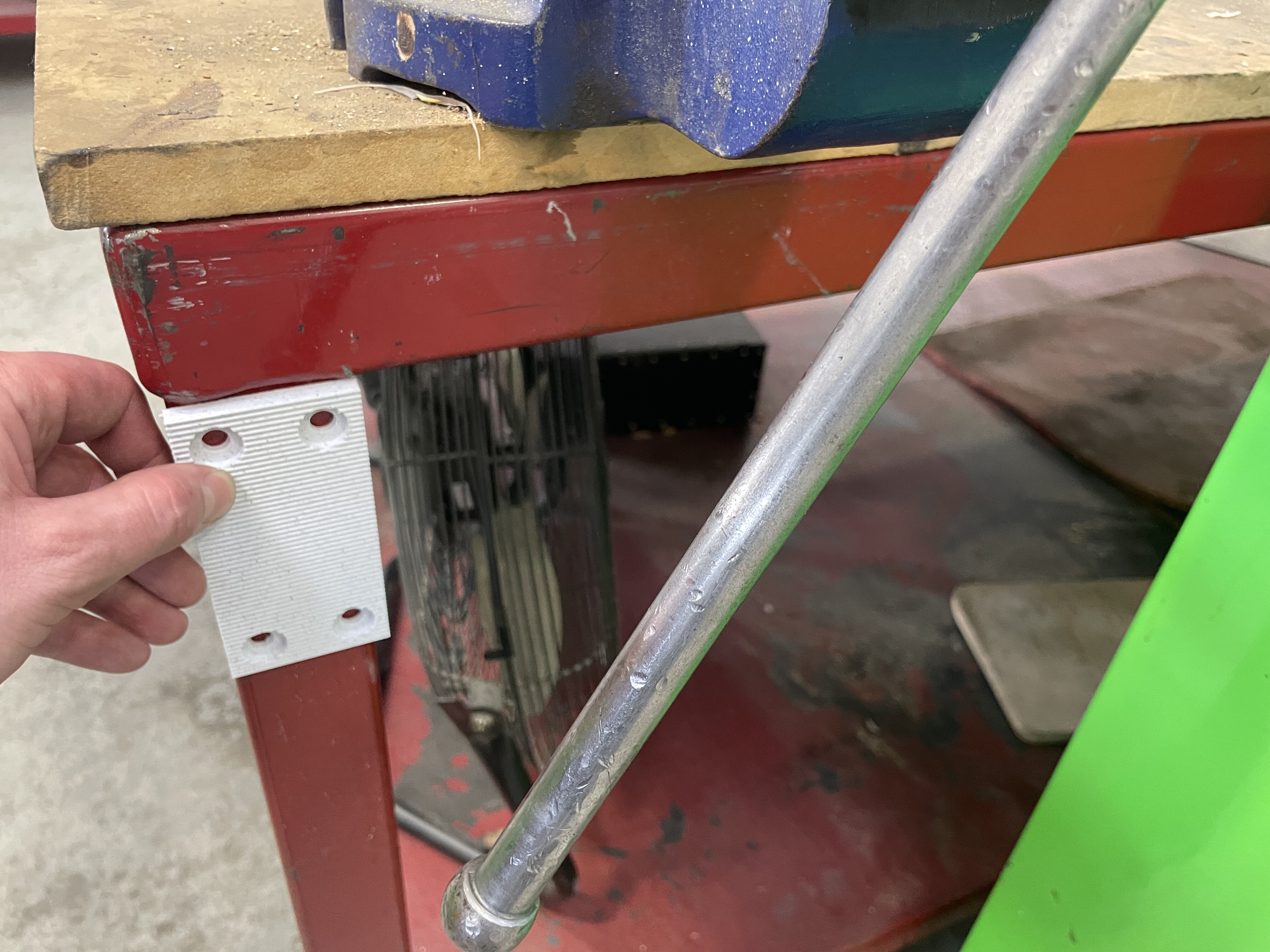
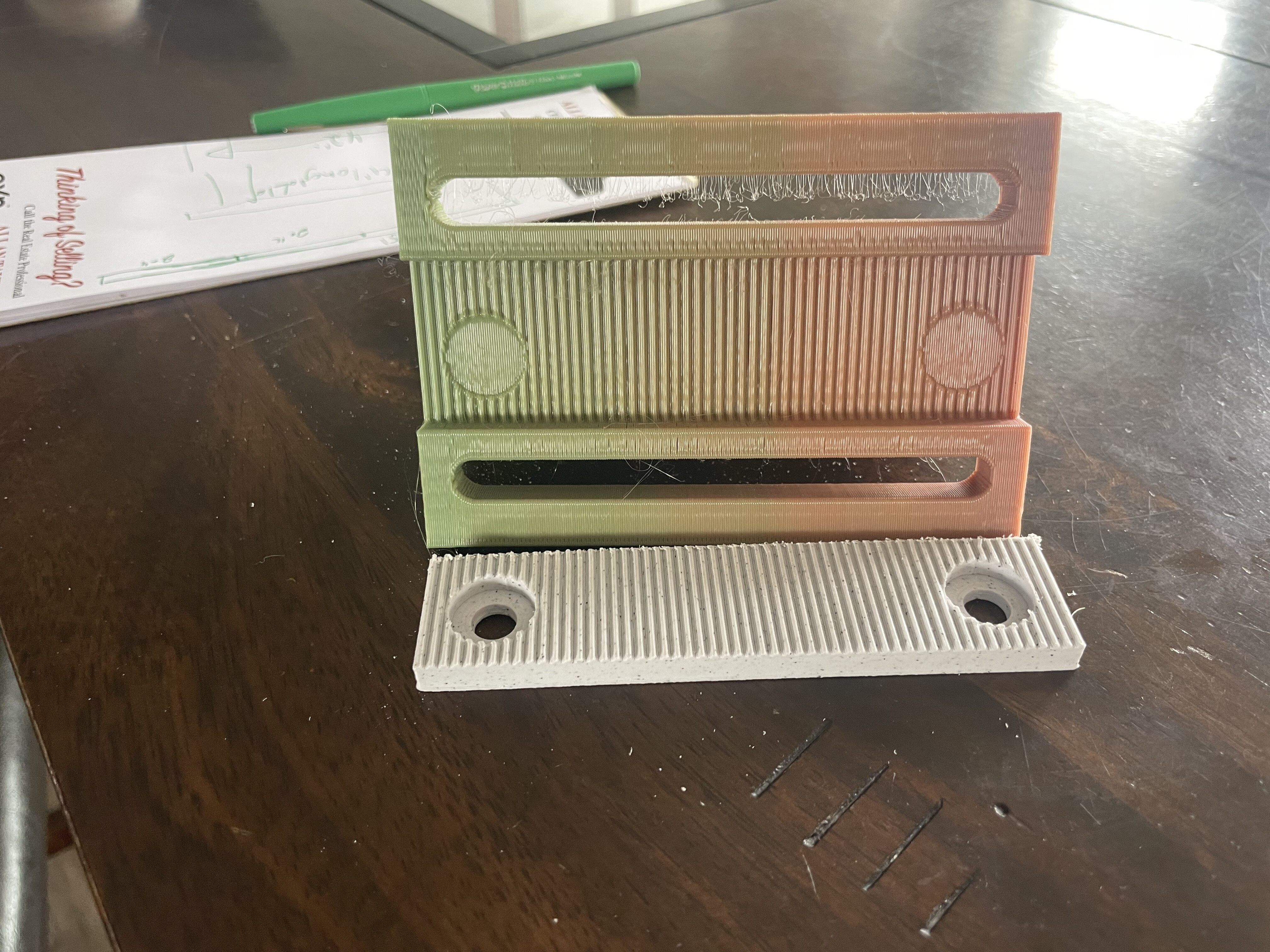
I want to use aerated bases mounted to the side of the table. The corner pieces would be long and serrations horizontal. These bases you’ll be squared up and permanently fixed to the table. And flush mounted.
The bracket would be serrated as well and it’s mounting holes elongated for tuning the bracket up or down about 1/2”. And being able to be marked so you can re install easily.
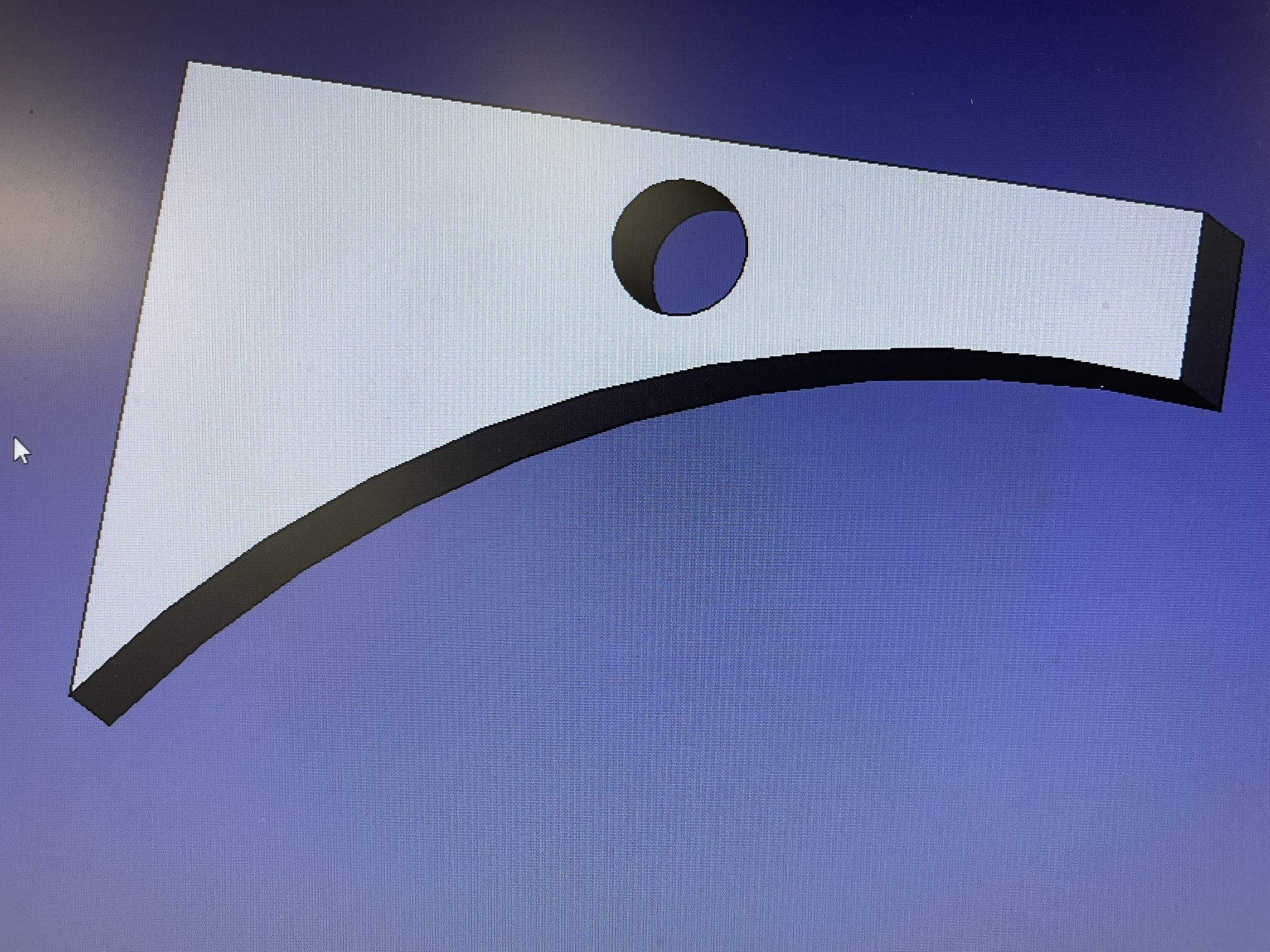
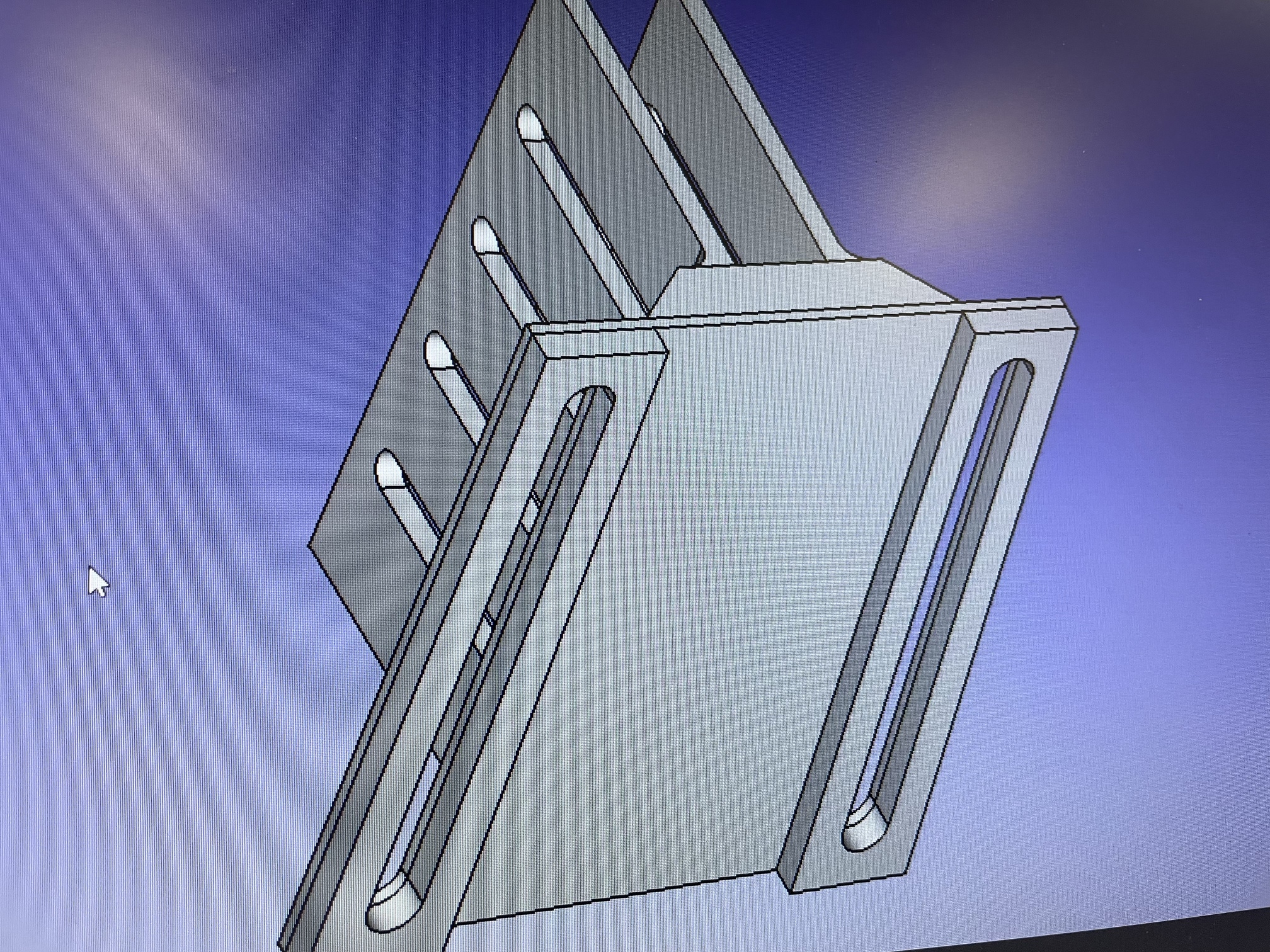
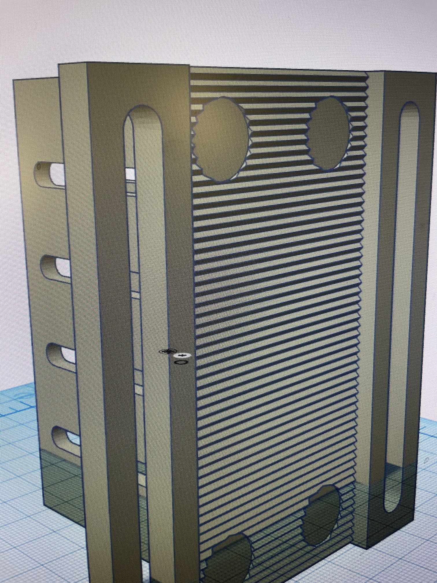
This is the example of the corner serrated mount. And the start of a corner angle bracket.
I will add flanges and elongated holes and the serrated face later.
As for the mid span brackets they would be 4” wide horizontal serrations and fixed on the outter frame. The angle brackets would be wide and have the same elongated holes for levelling.
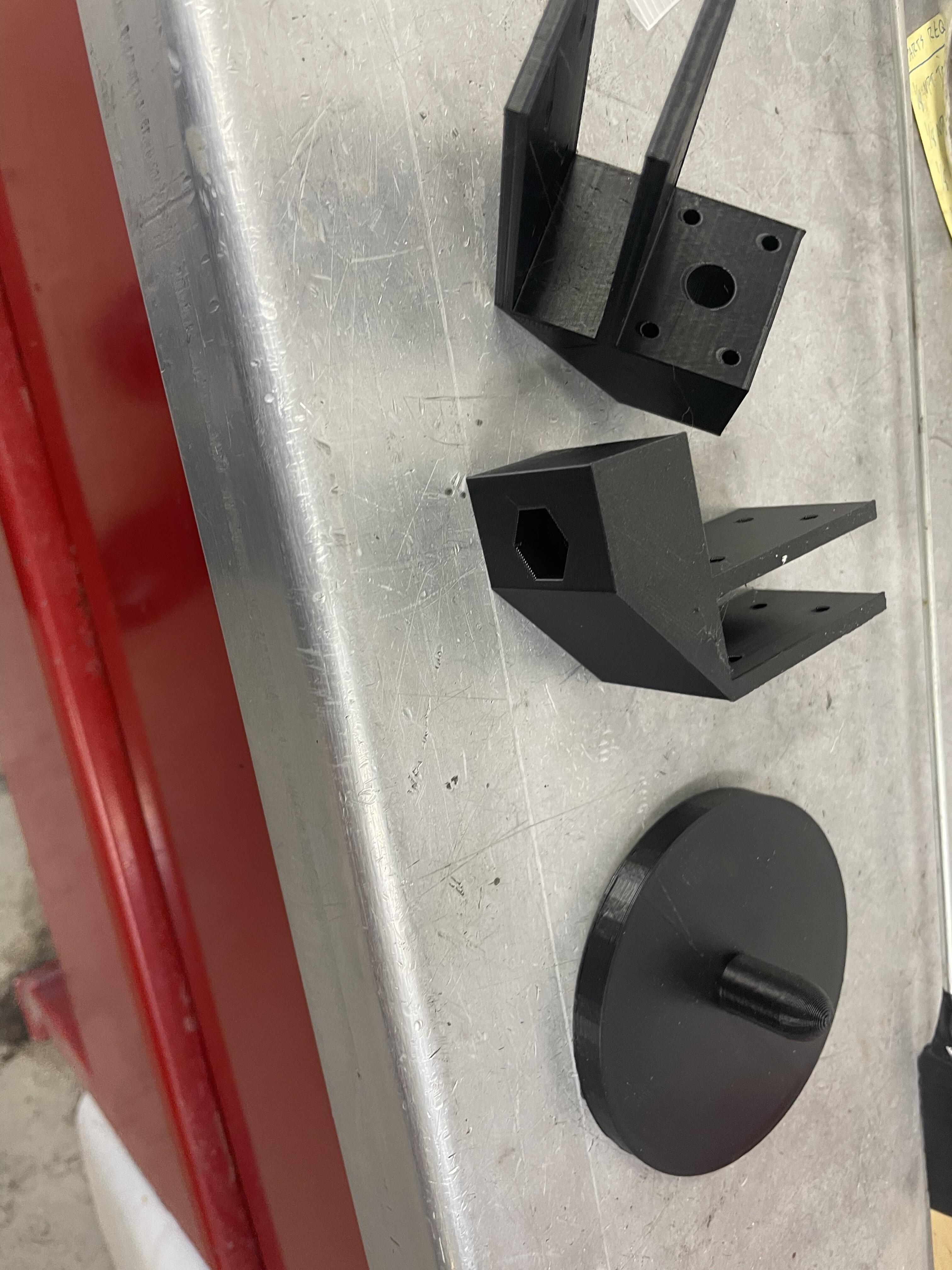
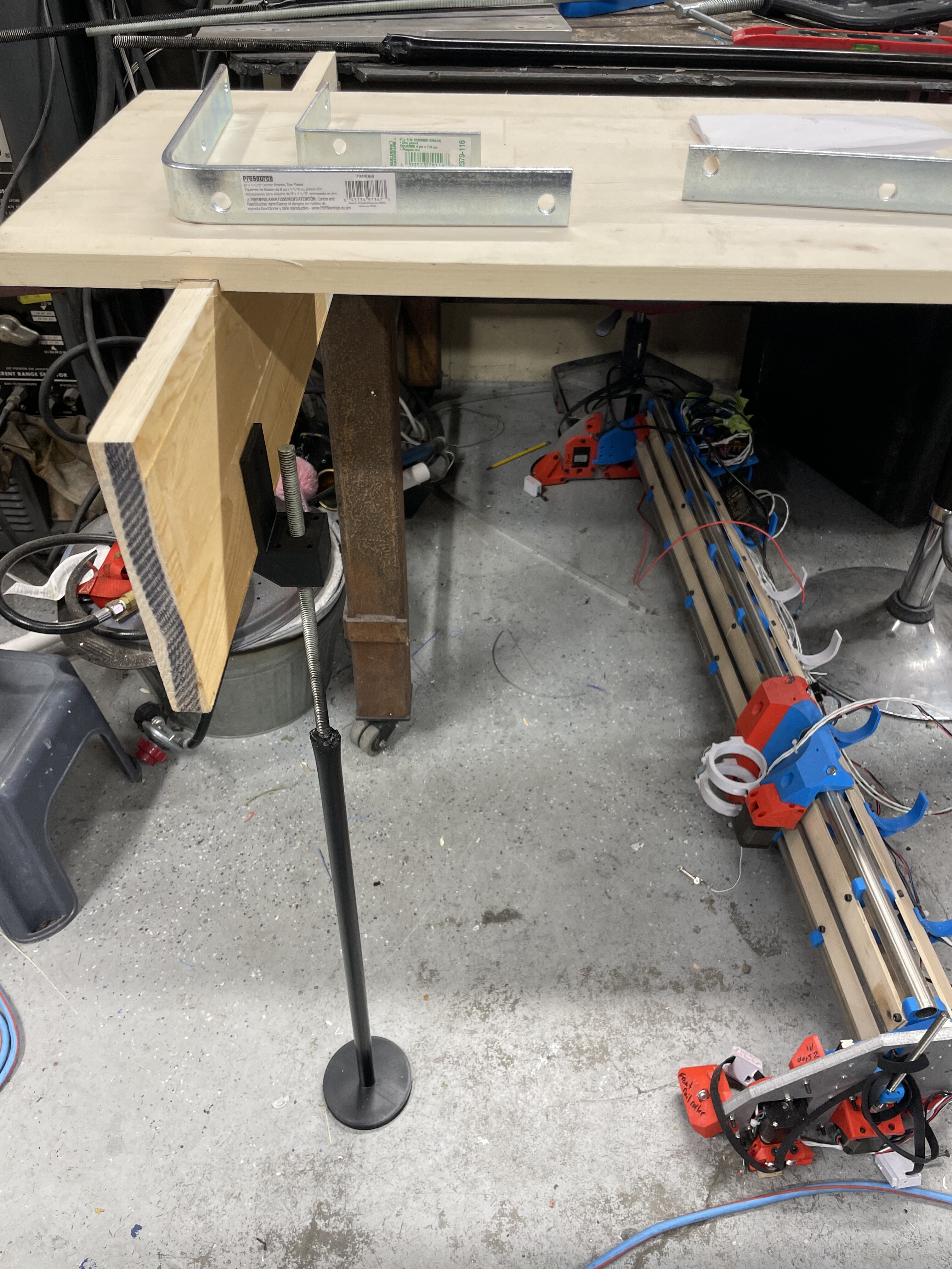
I also wanted to add 3/4” emt holes in the angle brackets to either tie them all together ( that would make the levelling tricky and not as independent) or just have a small 1’ section that goes through so you could use more 3/4” emf and have a threadable top on it so you can go from the floor with a bit of a foot pad up to the angle bracket to help with support and to try and keep the sag down.
Also want to make the brackets small enough for standard 3D printers so the extra support at the outter edge would help take the weight.
Basically I have no room for another work bench and if I can have a modular removable setup I can keep at work I will get a lot more use out of the machine.
I was inspired by Doug’s idea and I think supra had made some nice wooden table wings.
Anyways just more silly ideas on a Friday.
Actually I think a hing mount on the outside that has a jack screw that would fit in the end of some emt would be better.
Also for extra points who know what this cool tool is.
Well I think I am going forward with this.
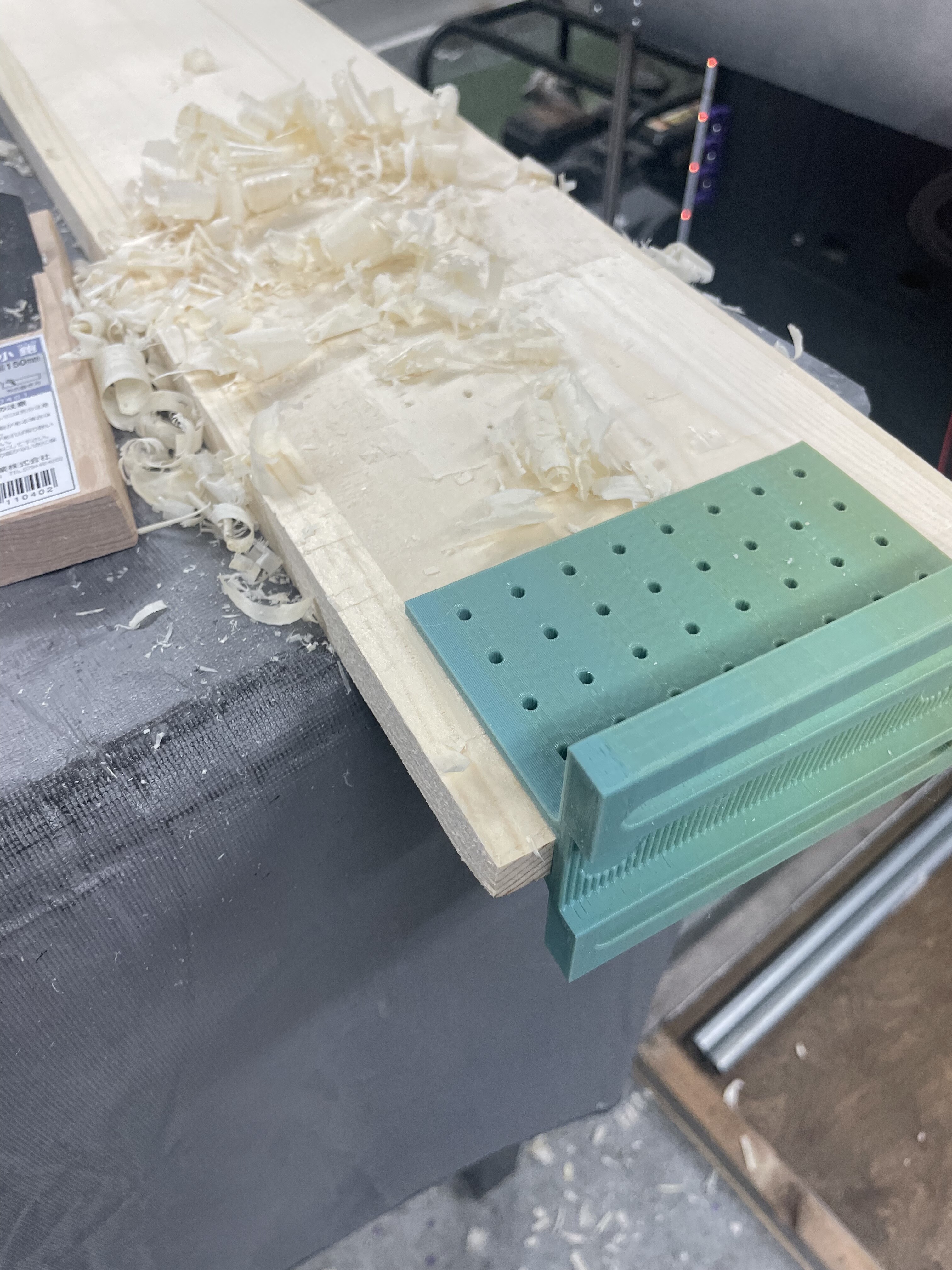
I have made this to fit my 16mm pine I have. These will be mounts so it can move around for levelling. I will use my mpcnc to cut the pine into a shape that fits in and will have some geometry for strength.
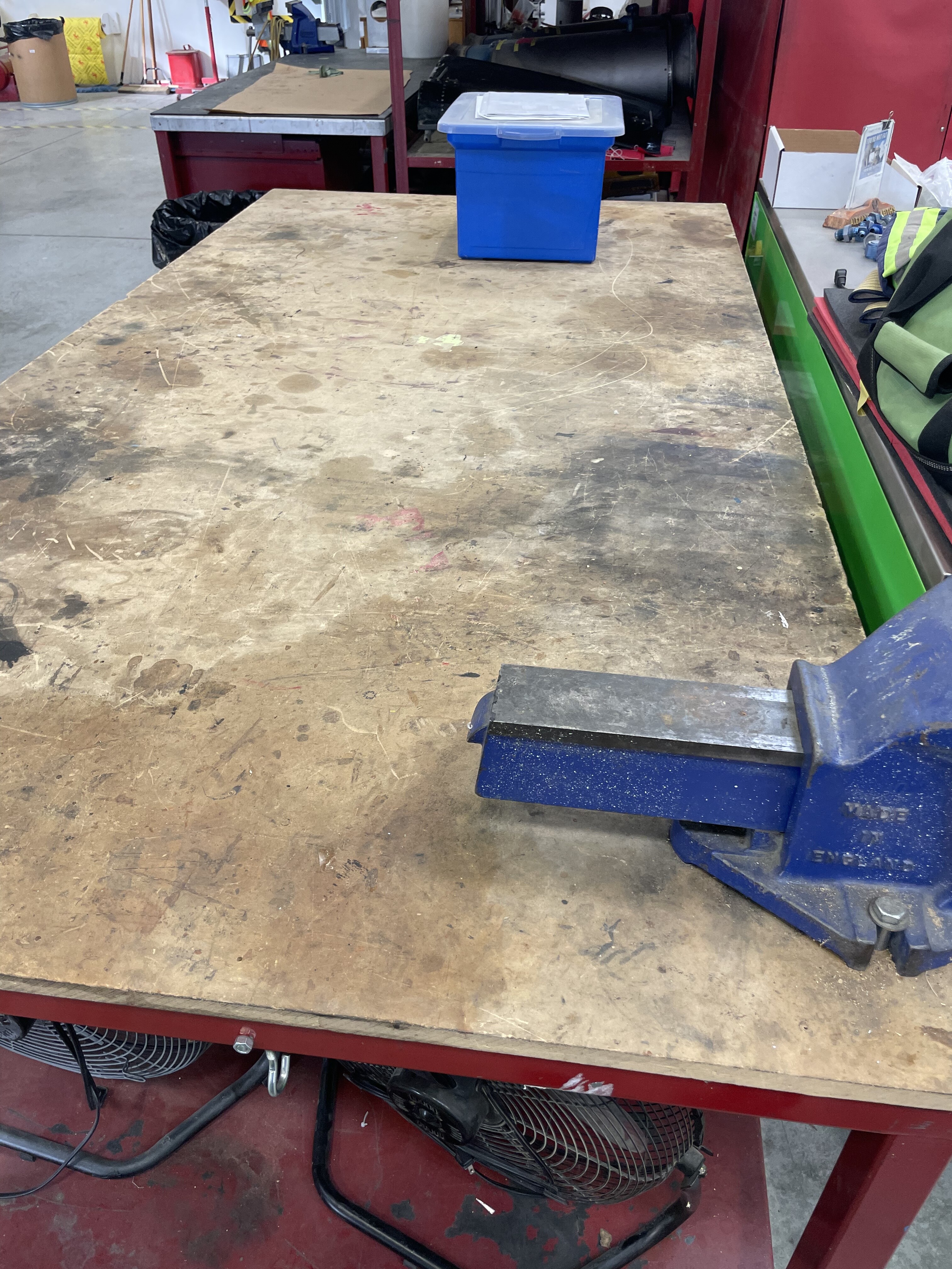
I stood in my garage for a good hour trying to figure out where I am going to store this table top etc. and ran through many ideas etc. and I think this is my easiest way.
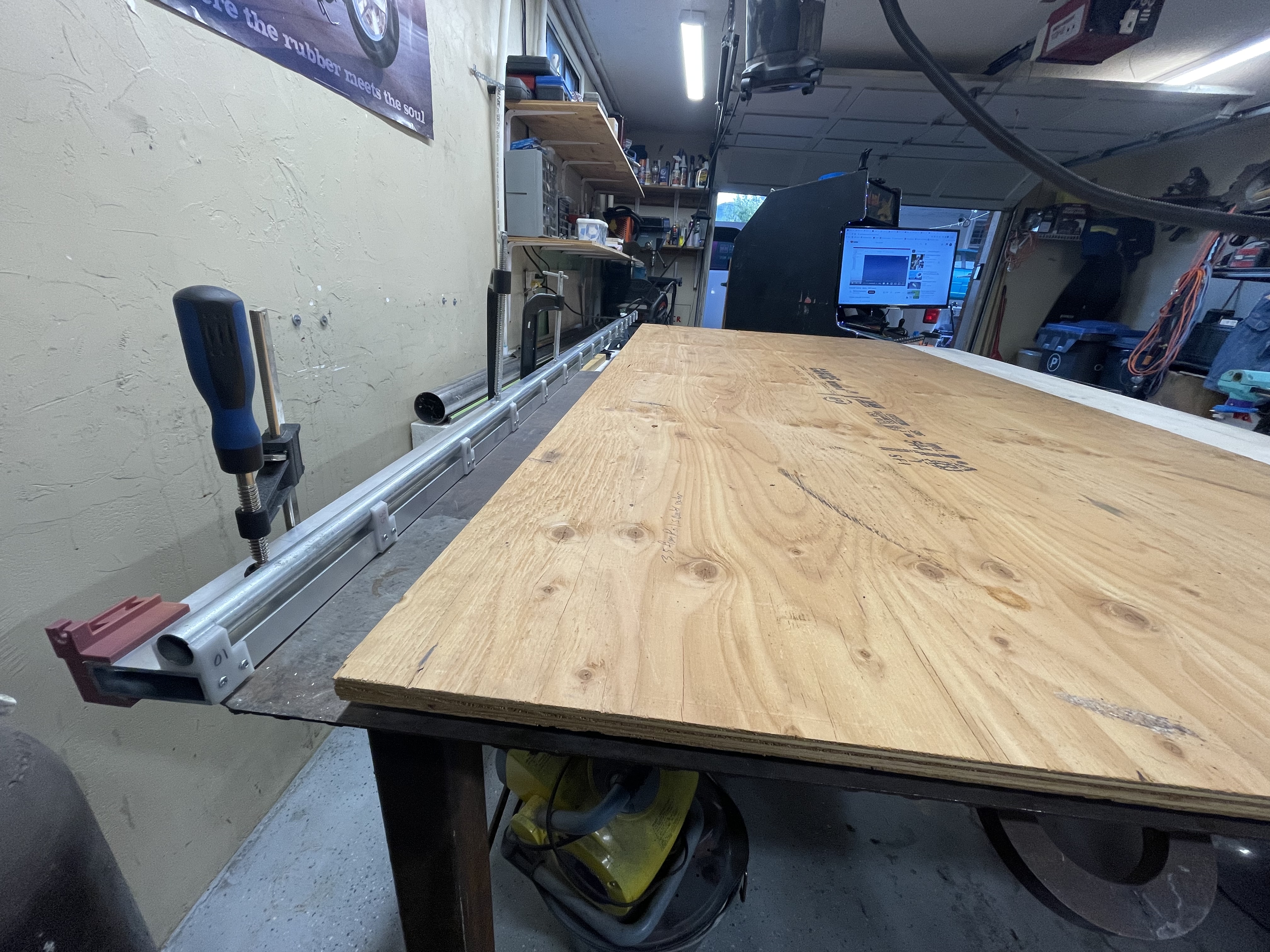
As I will be mounting a 4x8’ sheet on my welding table then using these table extender ears to mount my 30” extension pieces that I will level up with these brackets.
Well that’s the plan anyways.
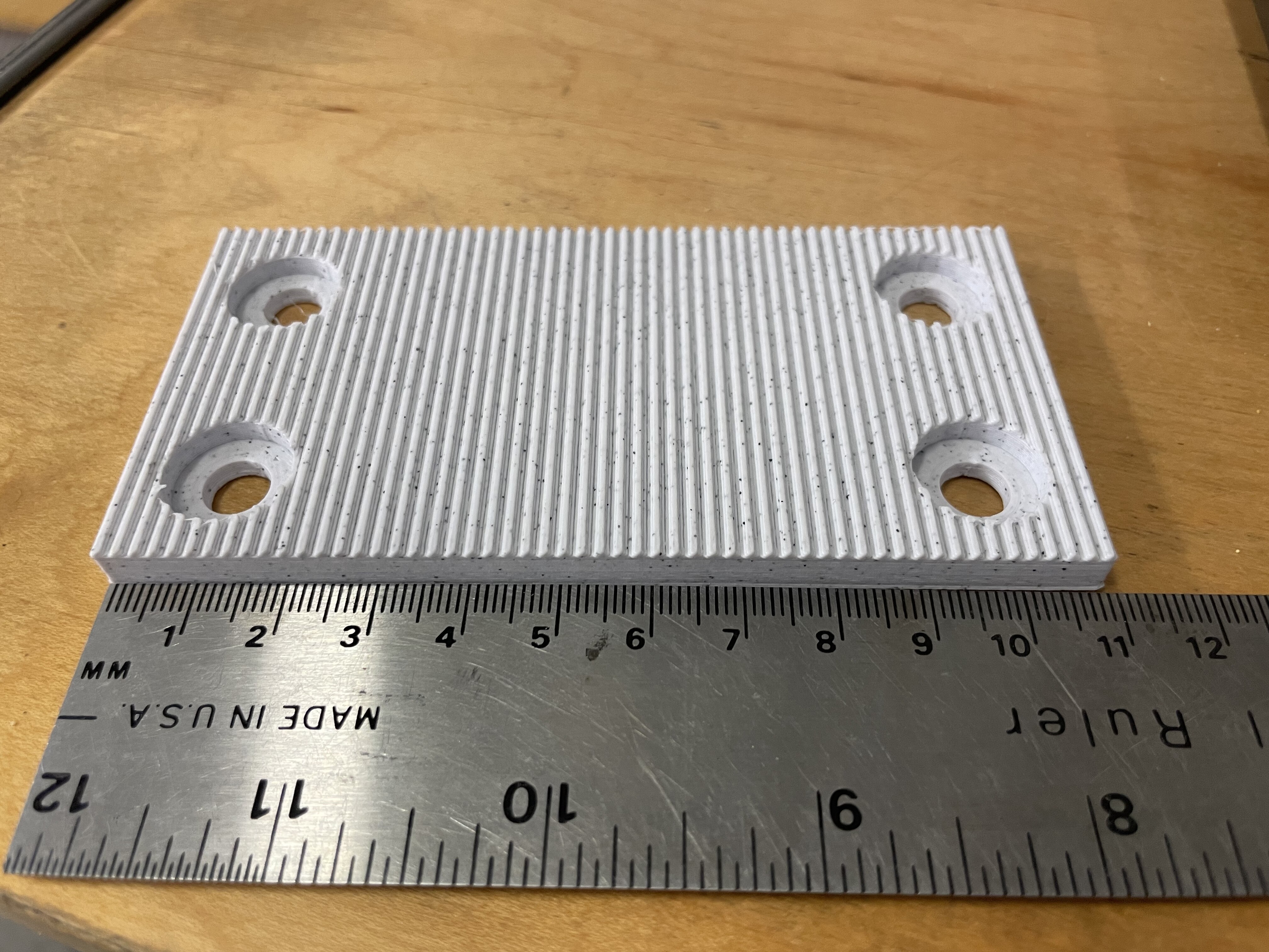
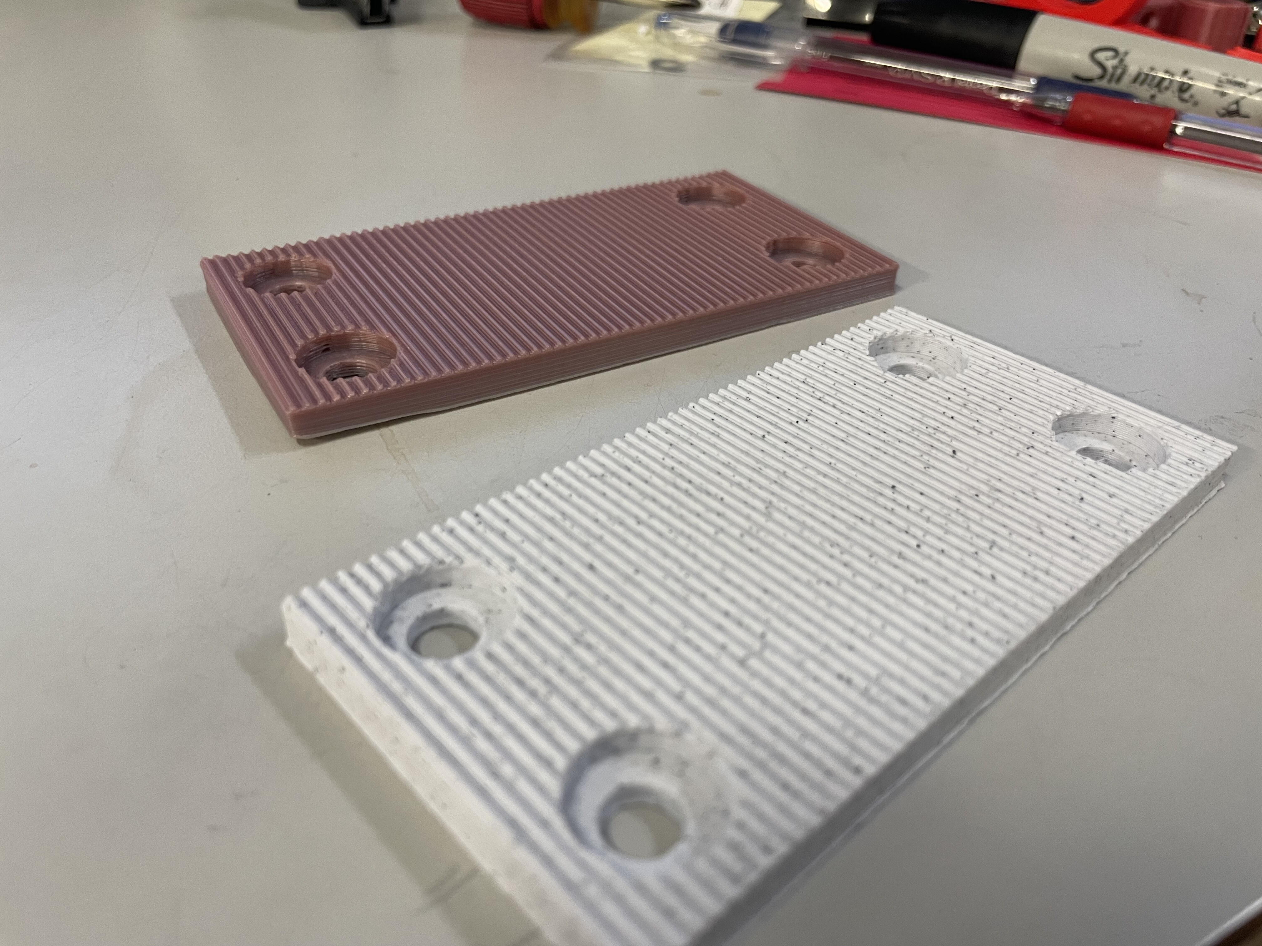
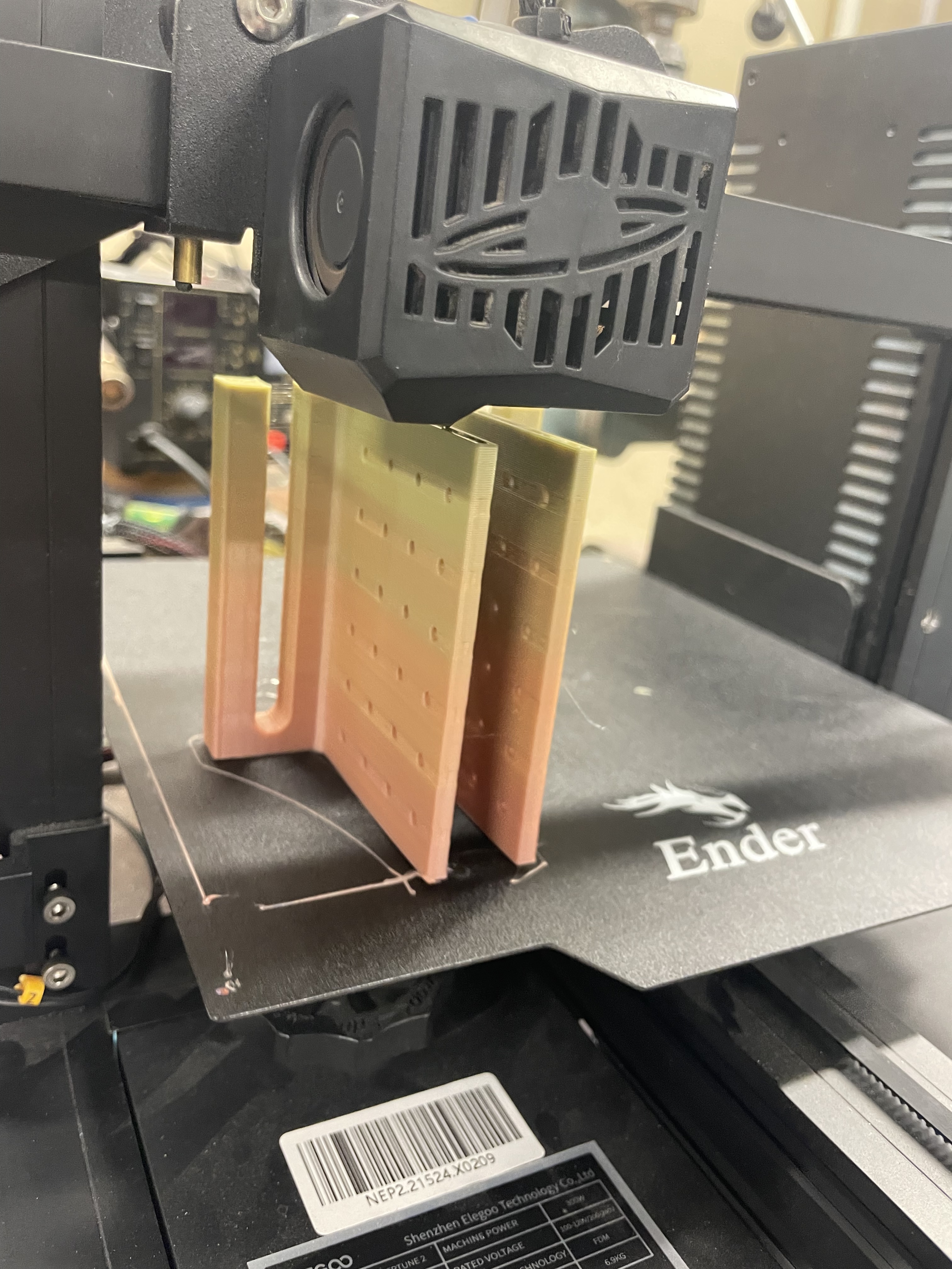
I modified the first version
And thought that multiple holes was better than slots in the bracket.
Then you can just put some wood screws in once it’s leveled and a couple more to lock it in.
Slow update. It now I have some space again.
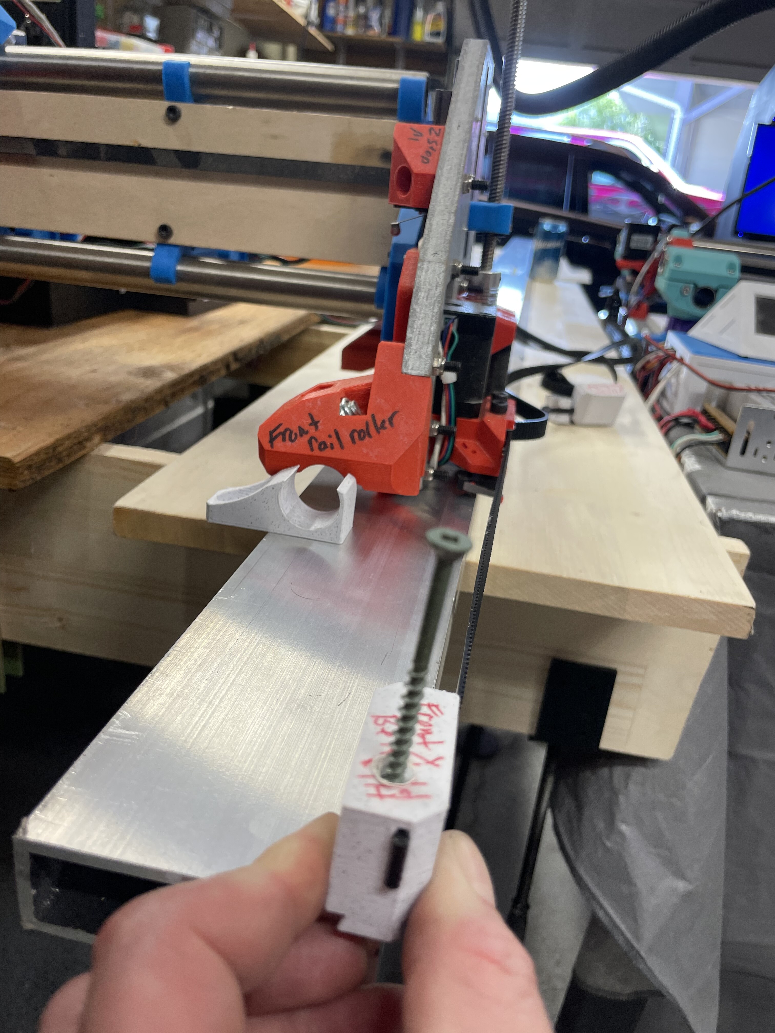
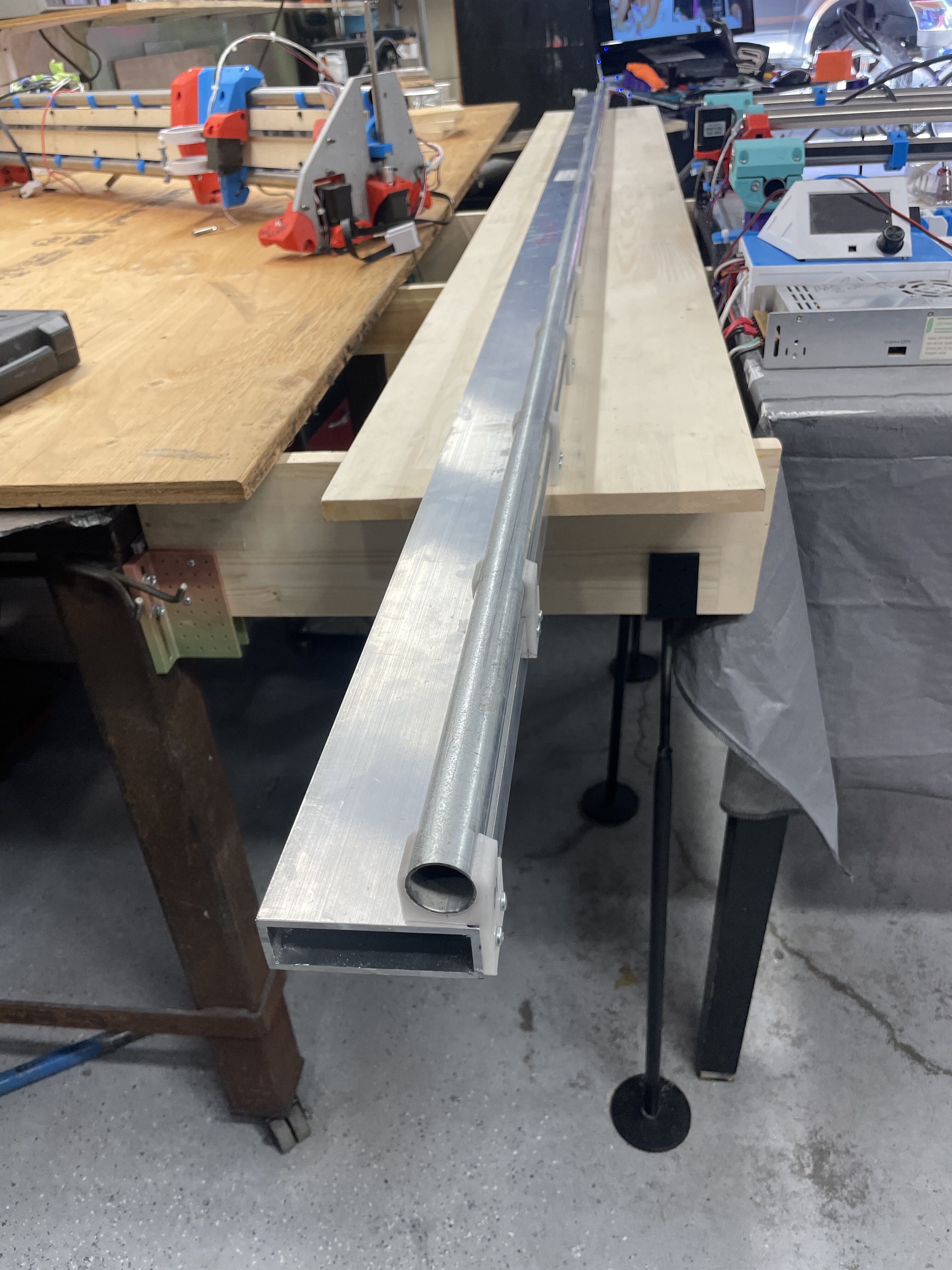
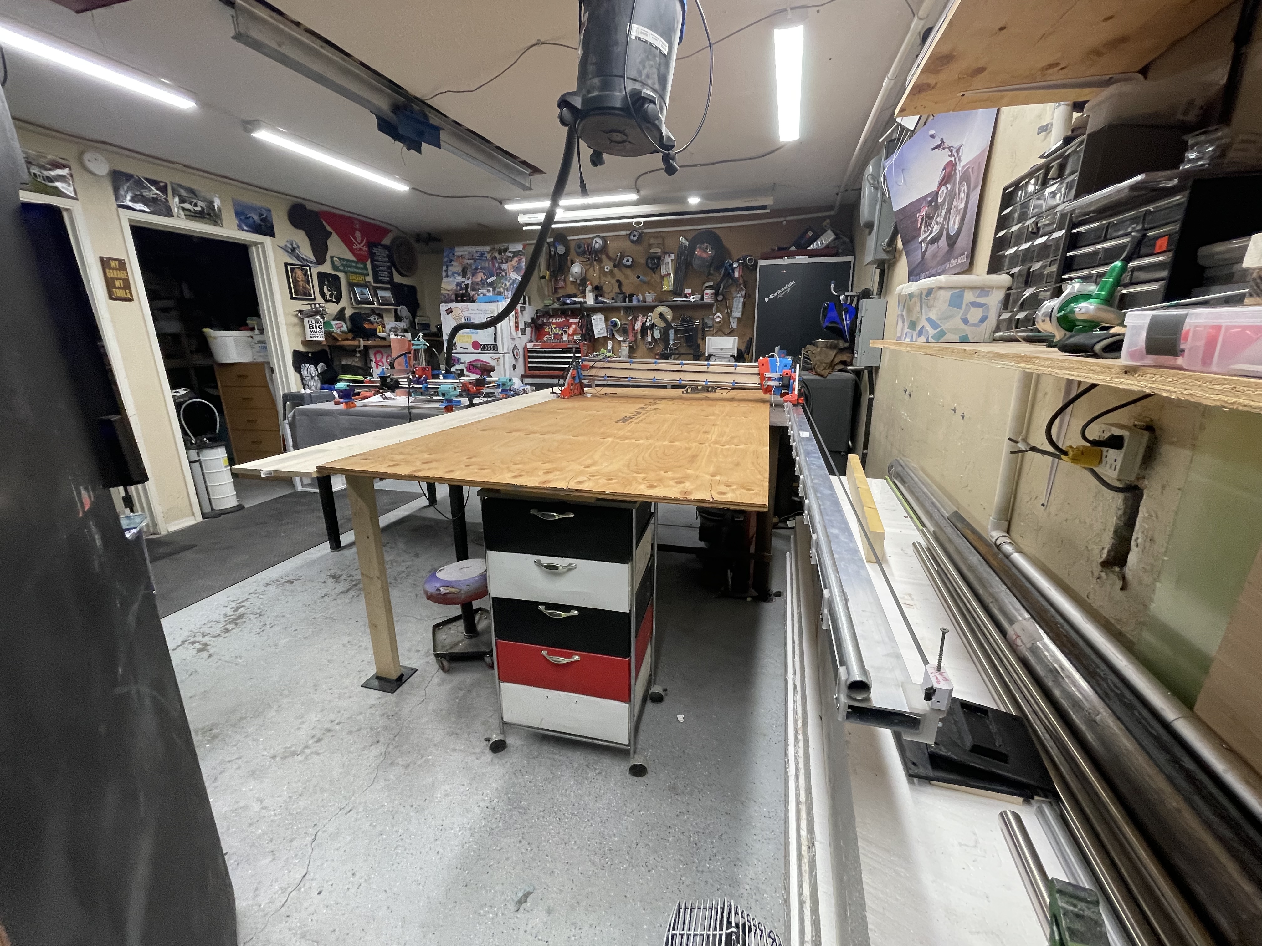
Going to do this for a table. And expanding my lr3 to use 5’ x tubes
The wheel side will be on the pine wood shelf
And the tube side has yet to be added it will be mounted to a 3x1” aluminum rectangle.
That’s the plan anyways
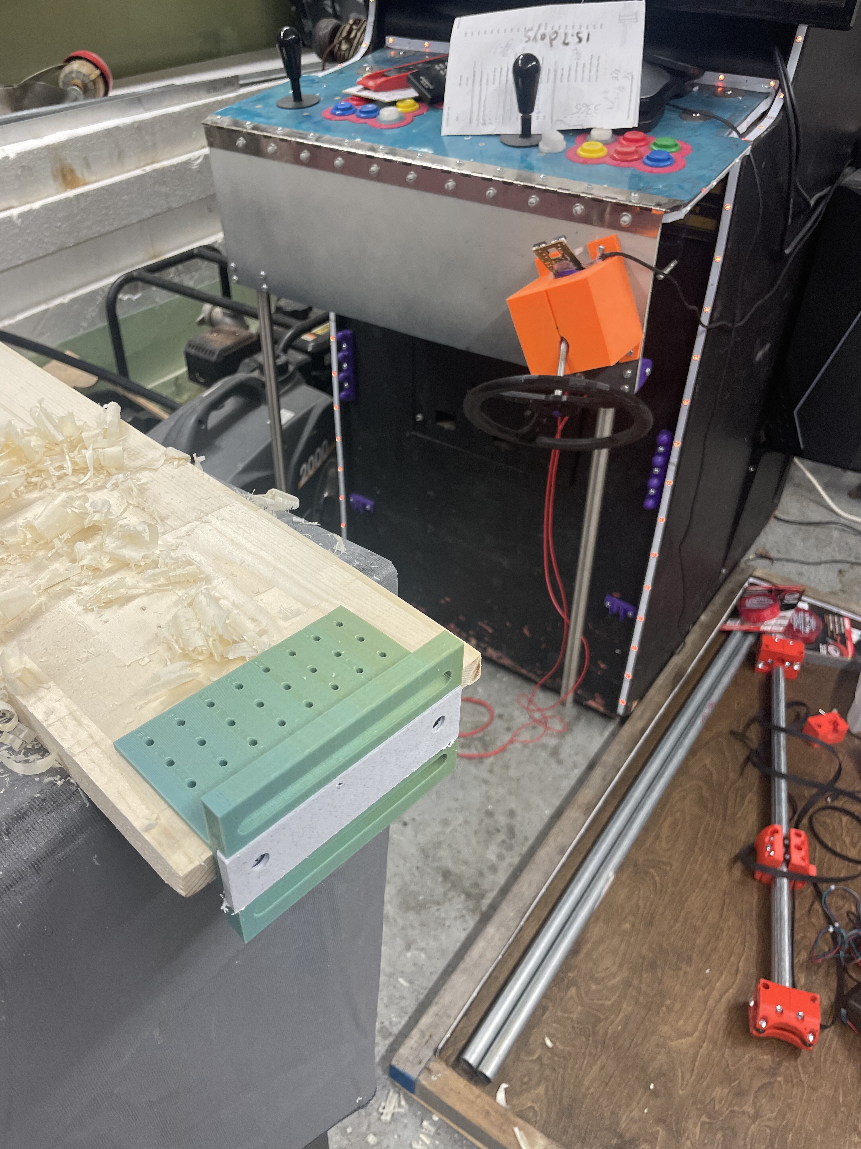
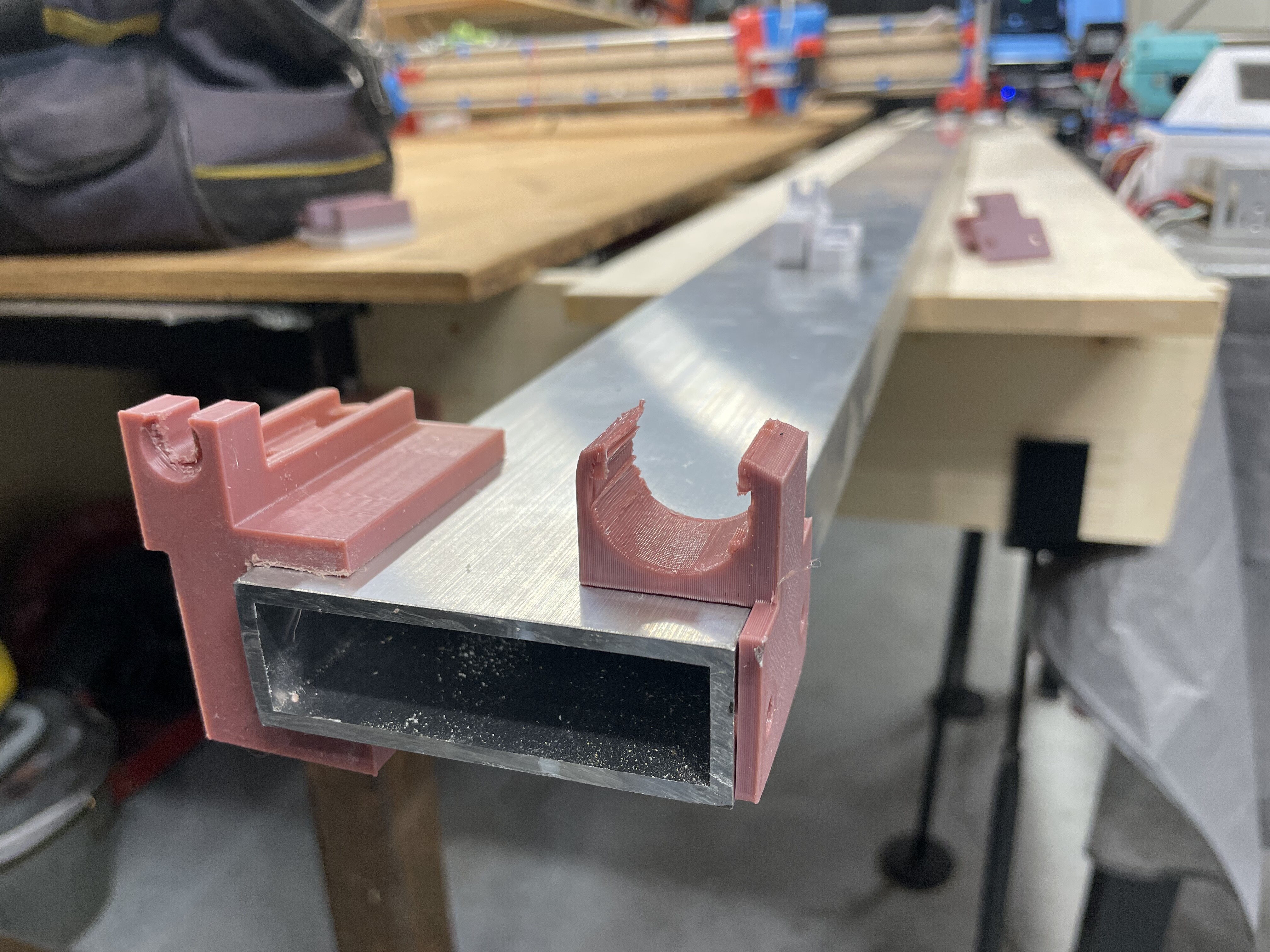
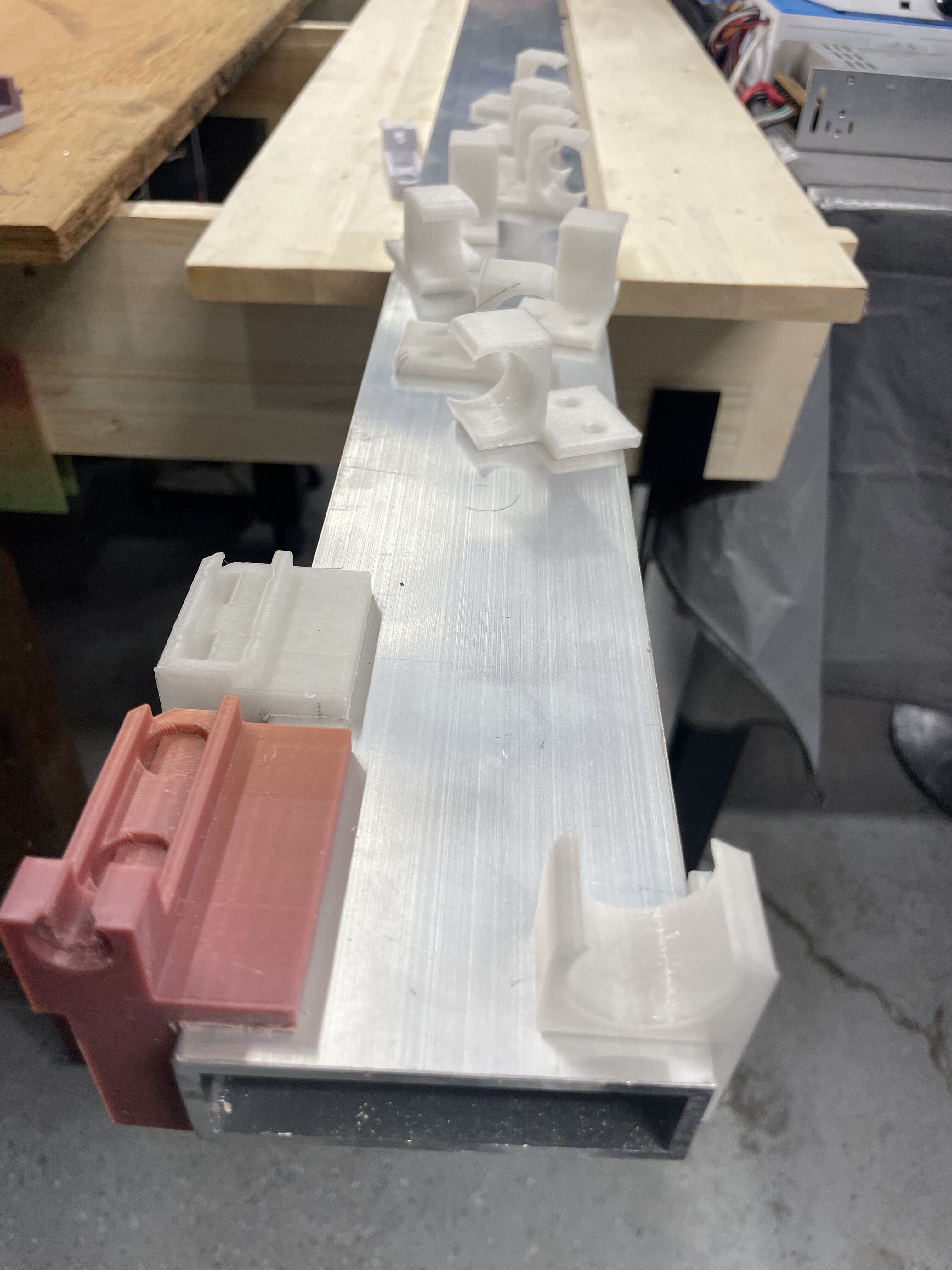
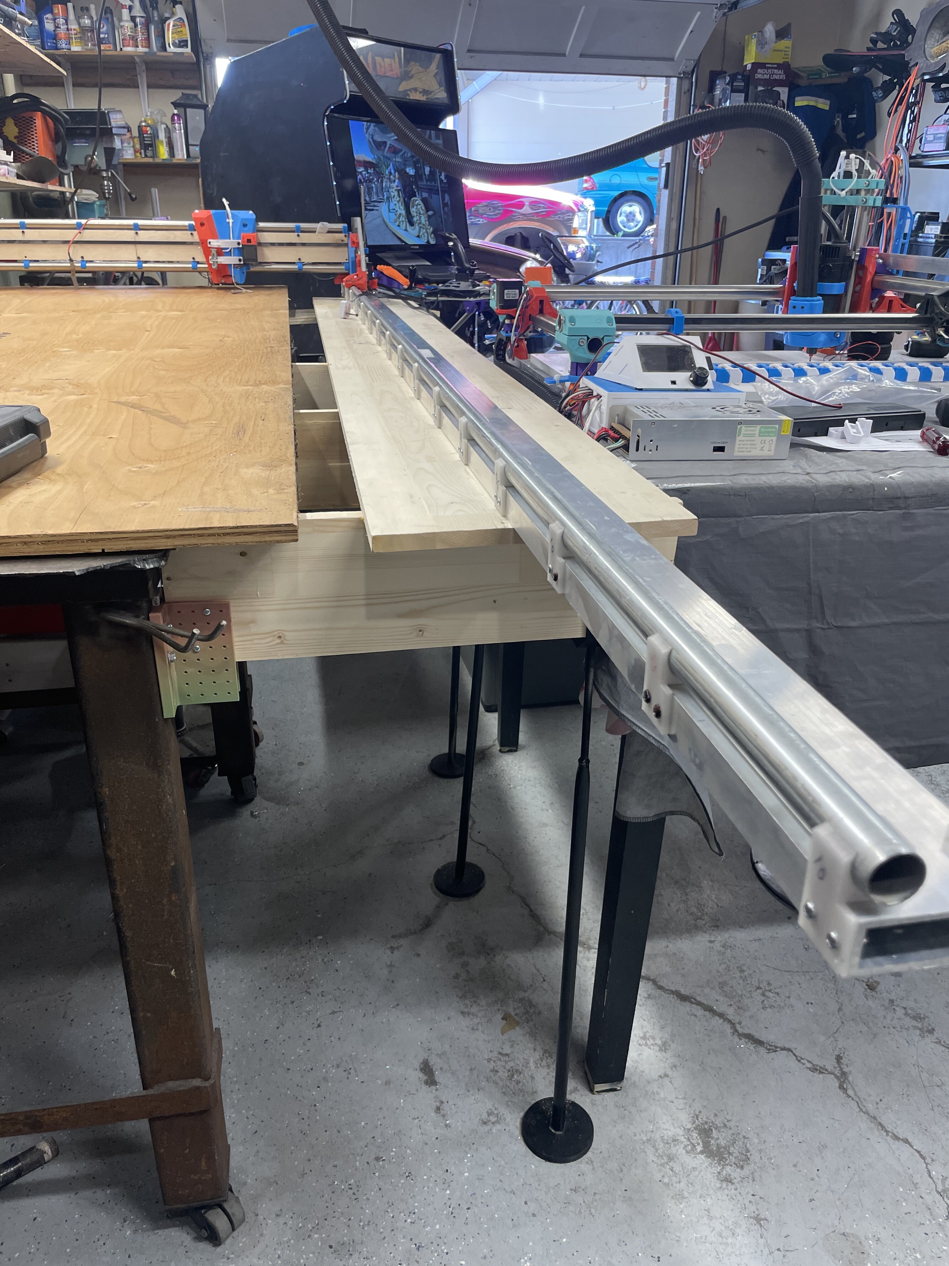
Couple updates
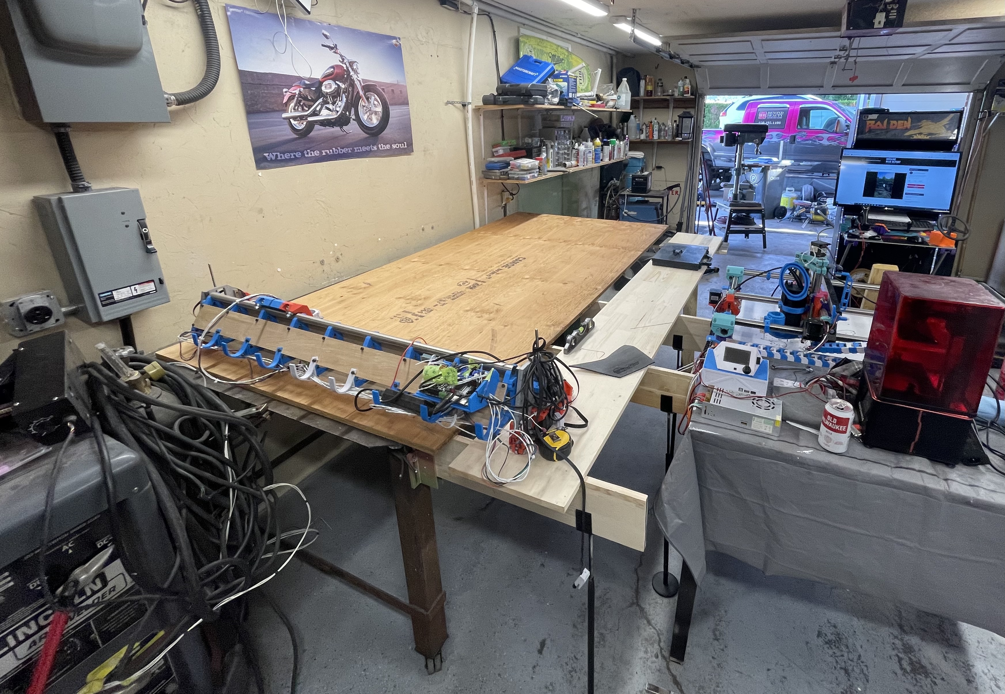
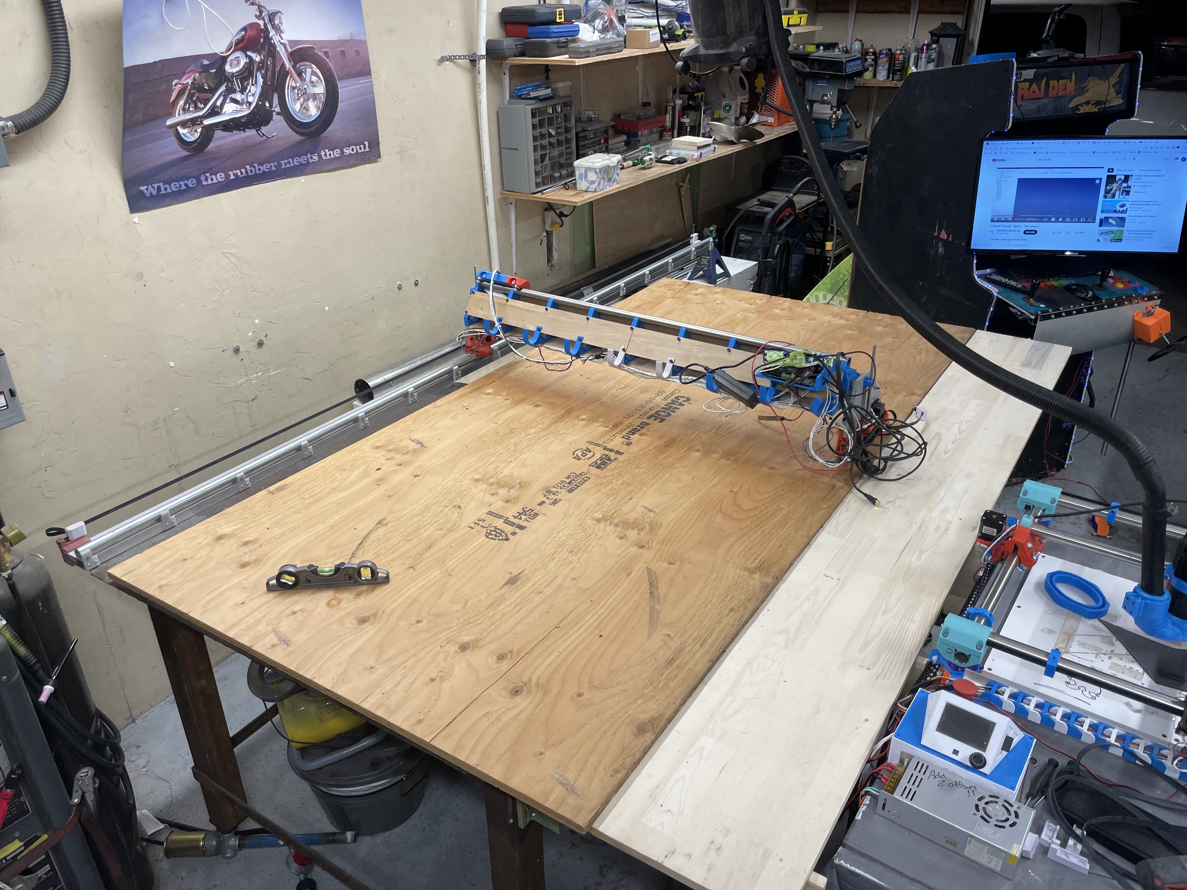
Things are rough mounted and dimensions work out for the use of full sheet.
I need to trim my extension wings and I am going to build a tension bridge for my long y so it should be independent.
Not sure if I should use a full triangle pulley setup or just two fixed points yet.
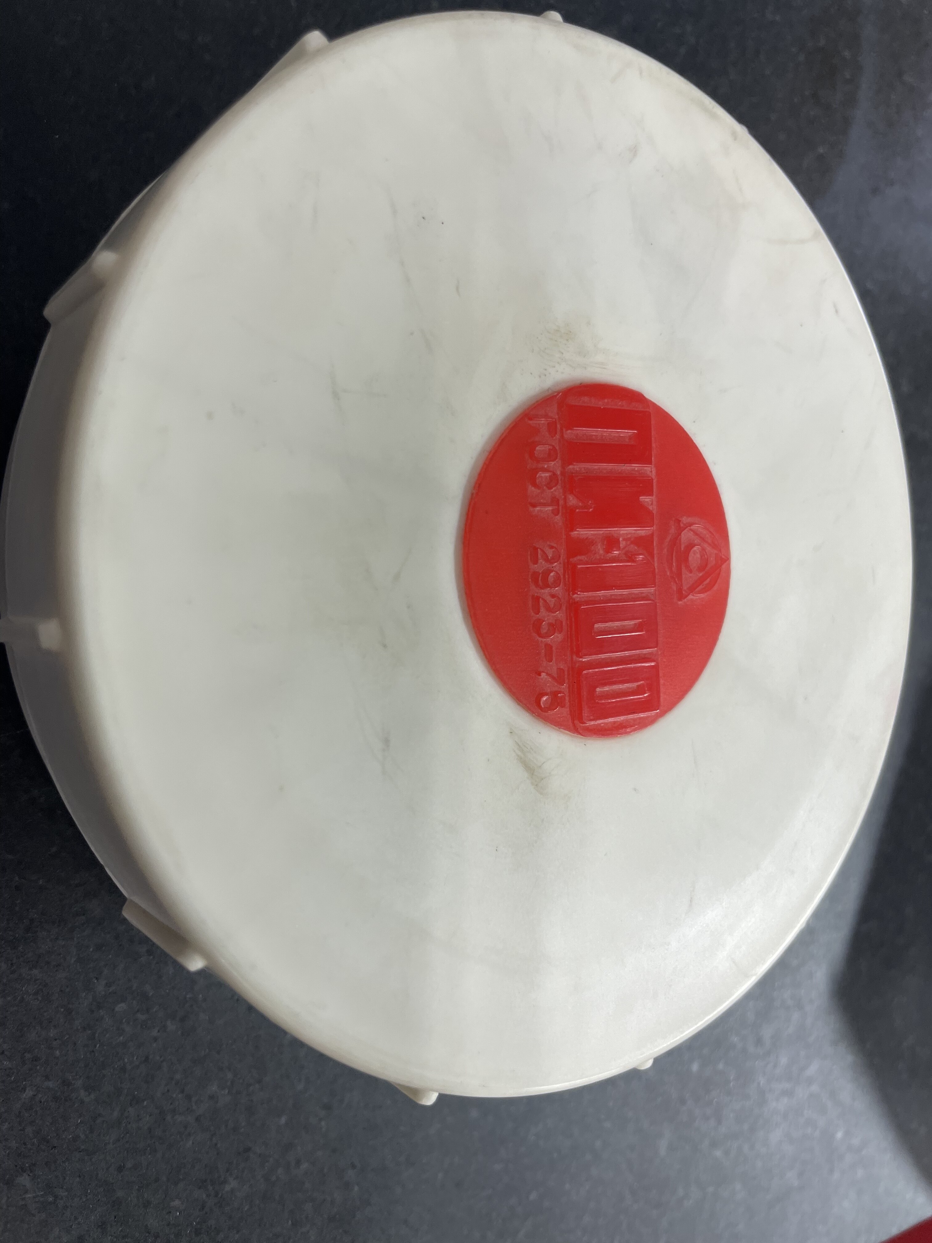
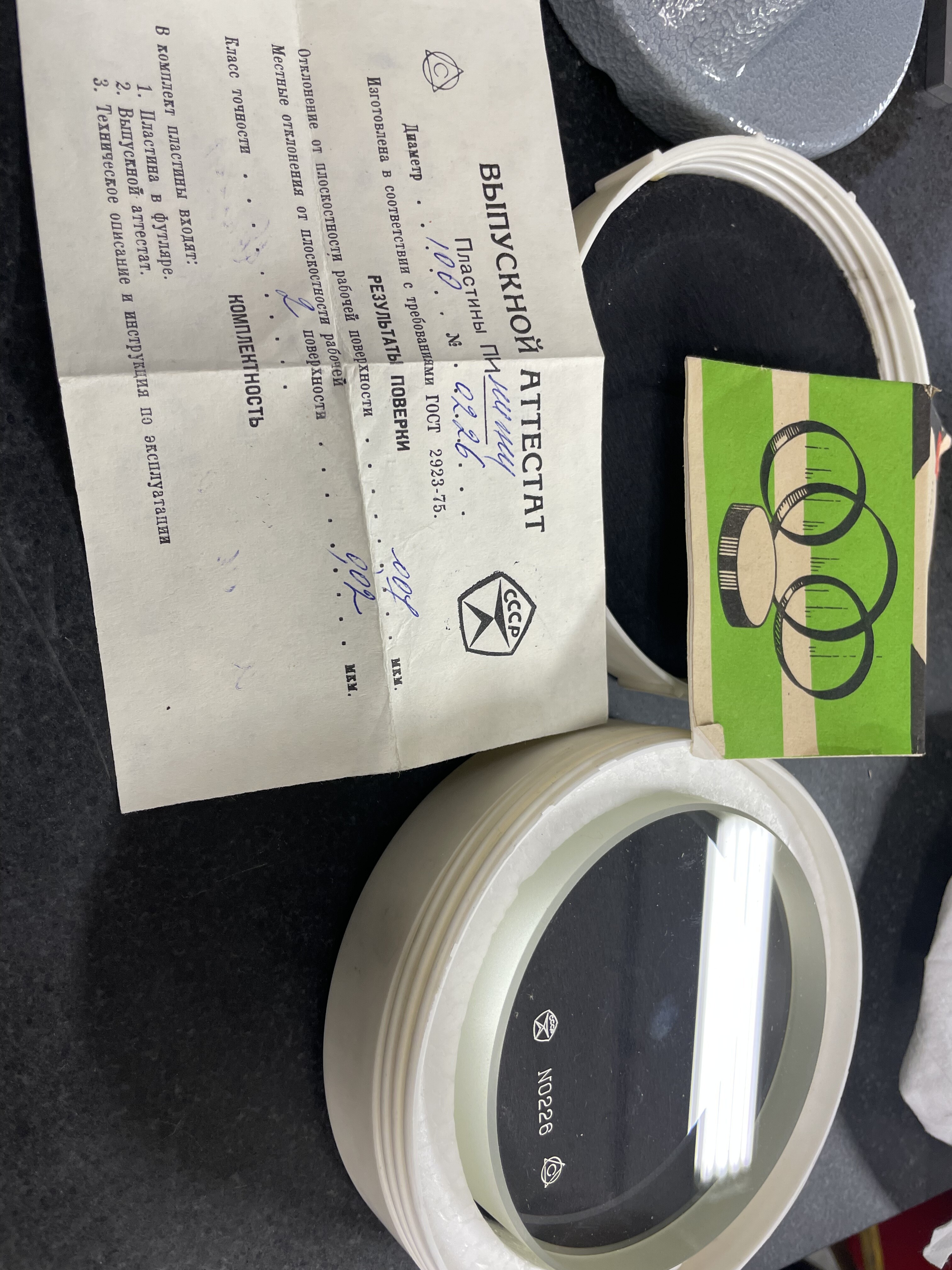
Without Google-translating the certification doc there, my guess would be some sort of calibration lens for either a mirror or focal apparatus? Maybe an interference lens for checking flatness of a surface? Either that, or a monocle for a party leader (I saw the CCCP) trying to compensate for something…
You are right it could have many jobs lol.
It’s for measuring optical flats. Supposed to use a green mono chromatic light. It amazes me the first time I used it and found out about it.
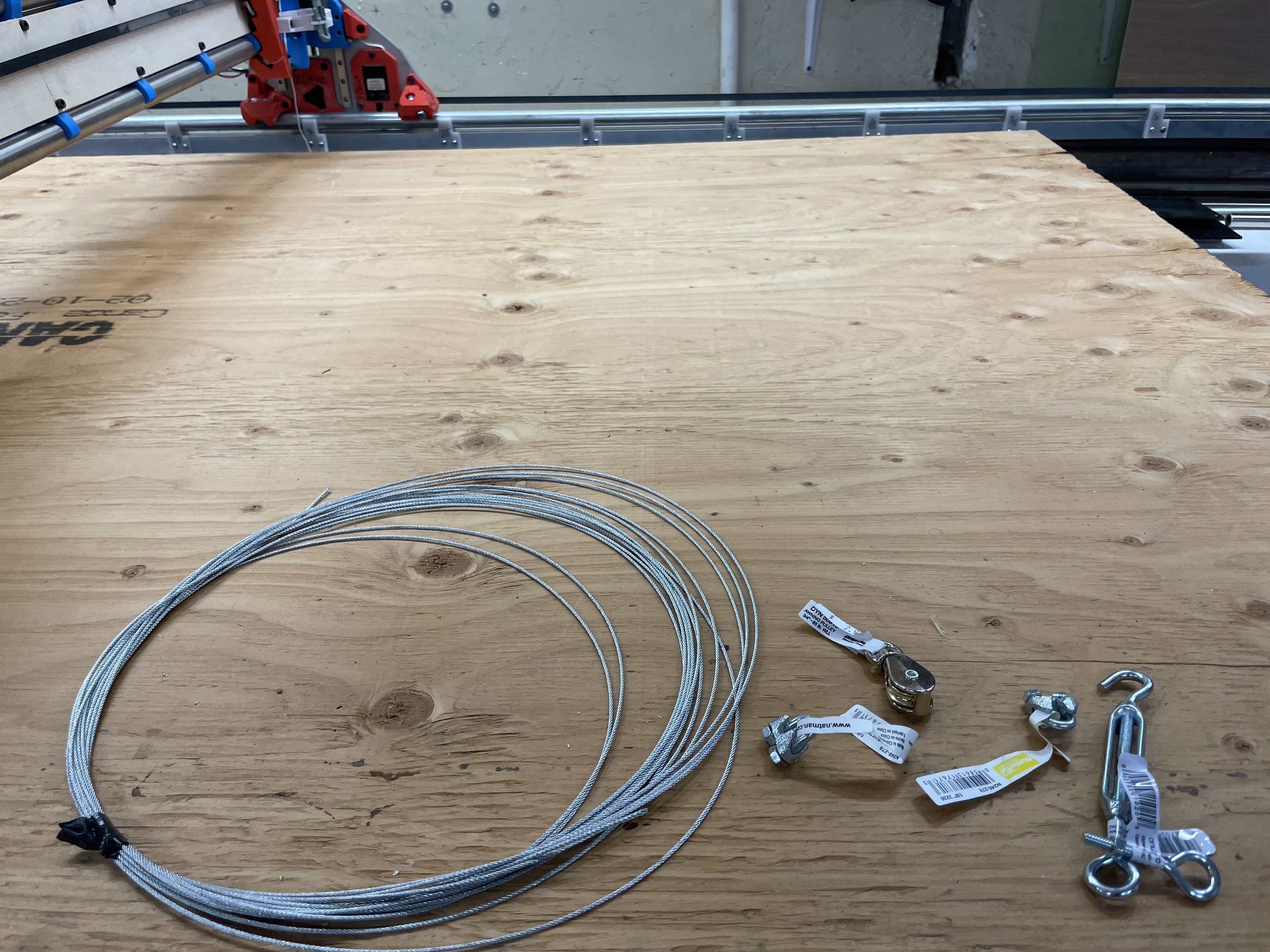
Decided on one single wire rope tension bridge for load sag.
One fixed end with a pulley as the apex and a turnbuckle at the other for adjustments.
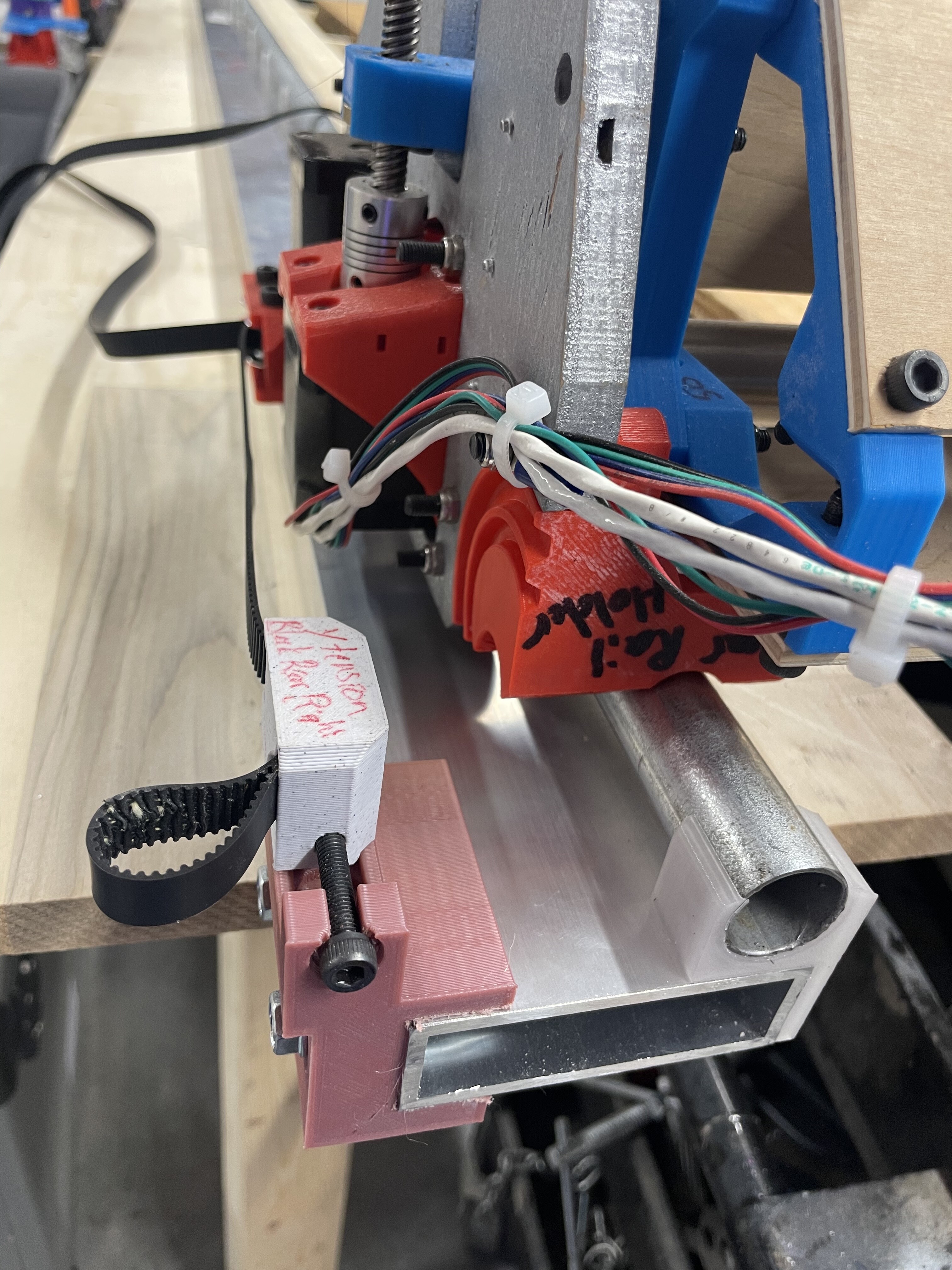
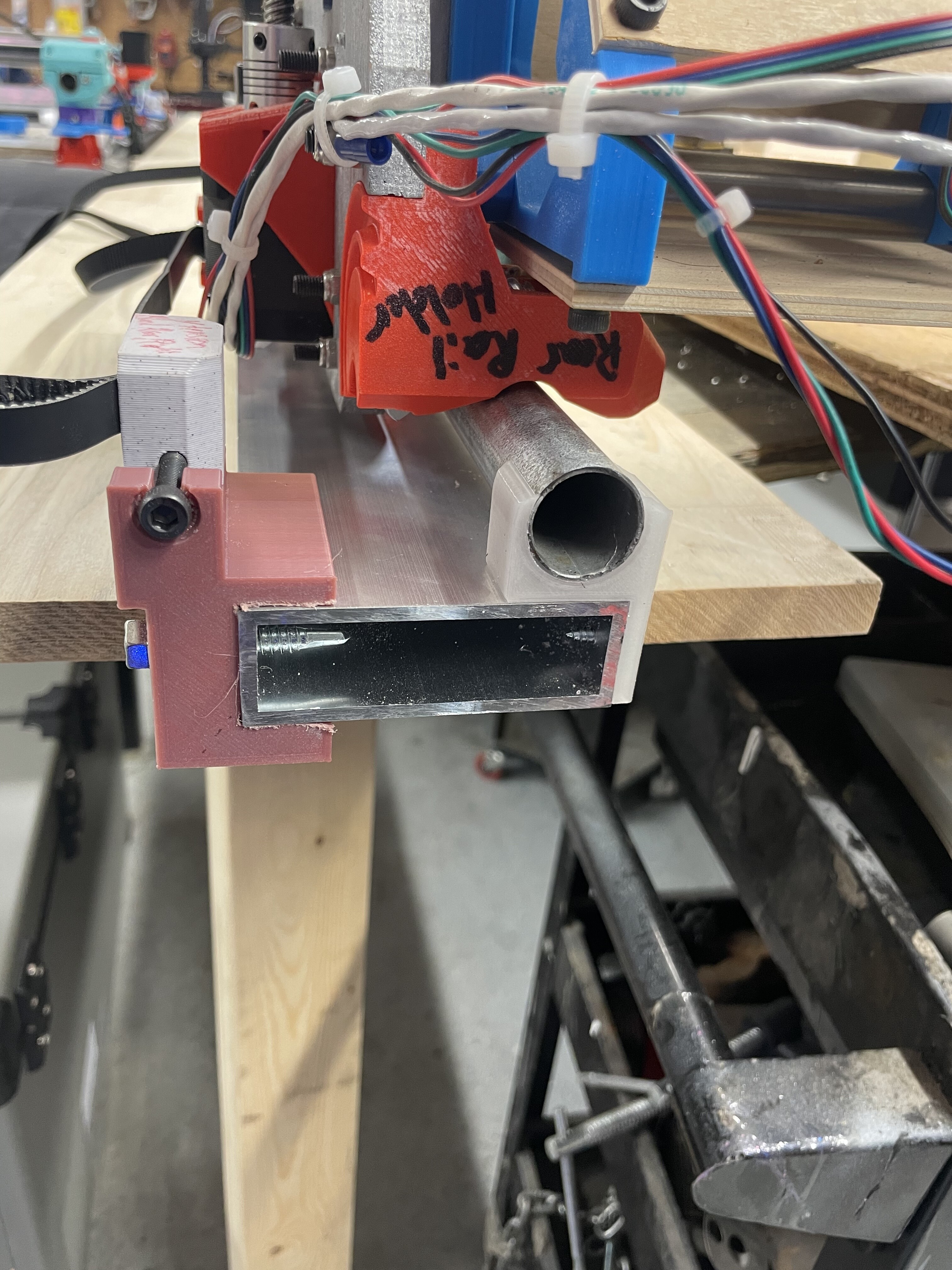
Toying with the idea of drilling through emt tube where the bearings don’t run and securing it to the beam with a half moon insert inside the OD of tubing and then just self tap to beam. That would also make it share the stress better. Goal is to be able to stand on the end and have no deflection with a 1/3 support lol.
It will make sense when it’s done, I want to open the market up for making old tables have new life new designs.
Like portably mount to any dining room table to do designs and possible infill.
Always good to have a goal but it’s ambitious for sure.
Been delayed with having chipmunk cheeks from wisdom teeth surgery.
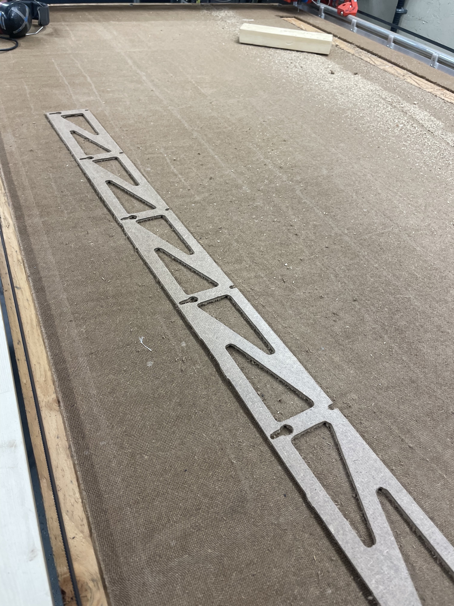
But I am almost at the point where I can cut my “forever struts”lol.
As you can see from my fugly ones that are on there now.
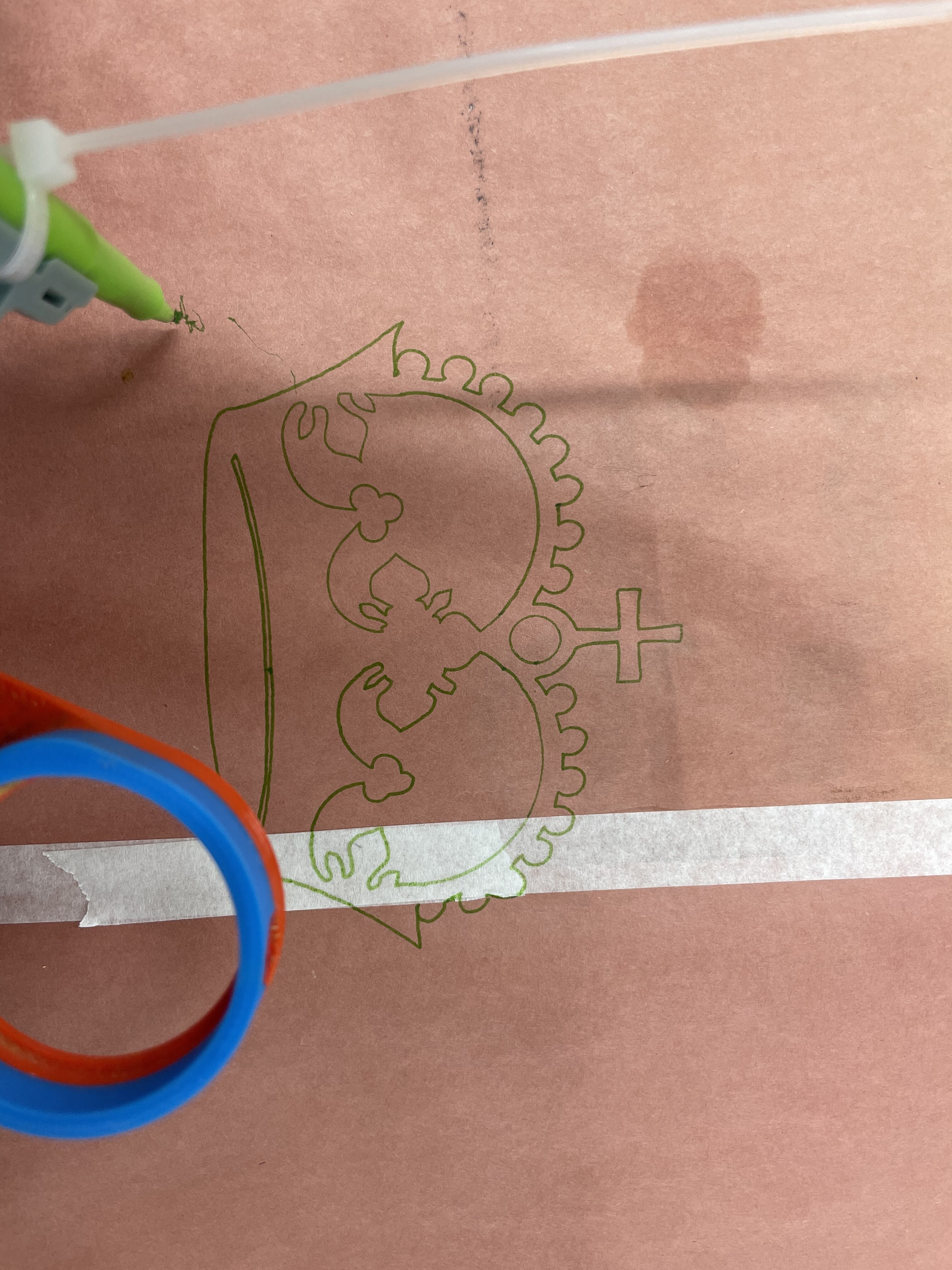
I did get a decent crown print and I can’t wait to get started on the parts for the tension wire.
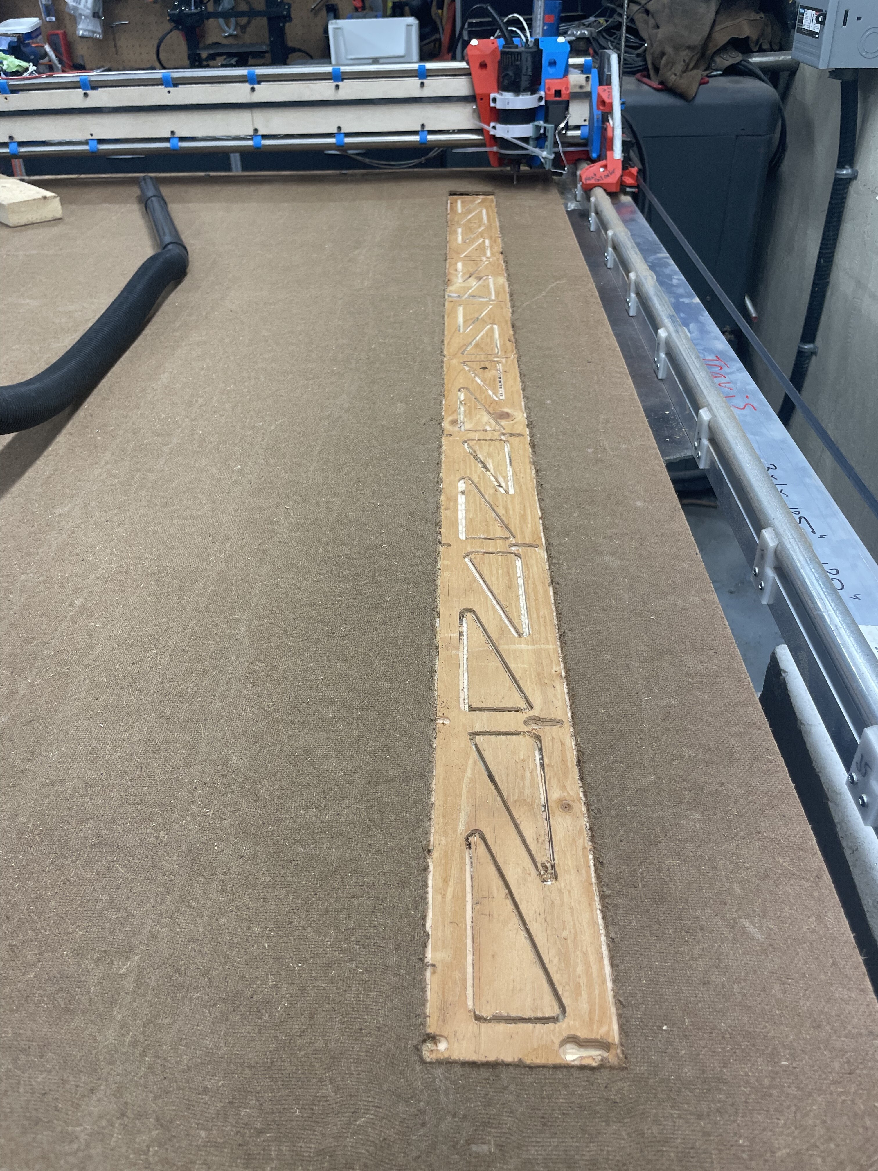
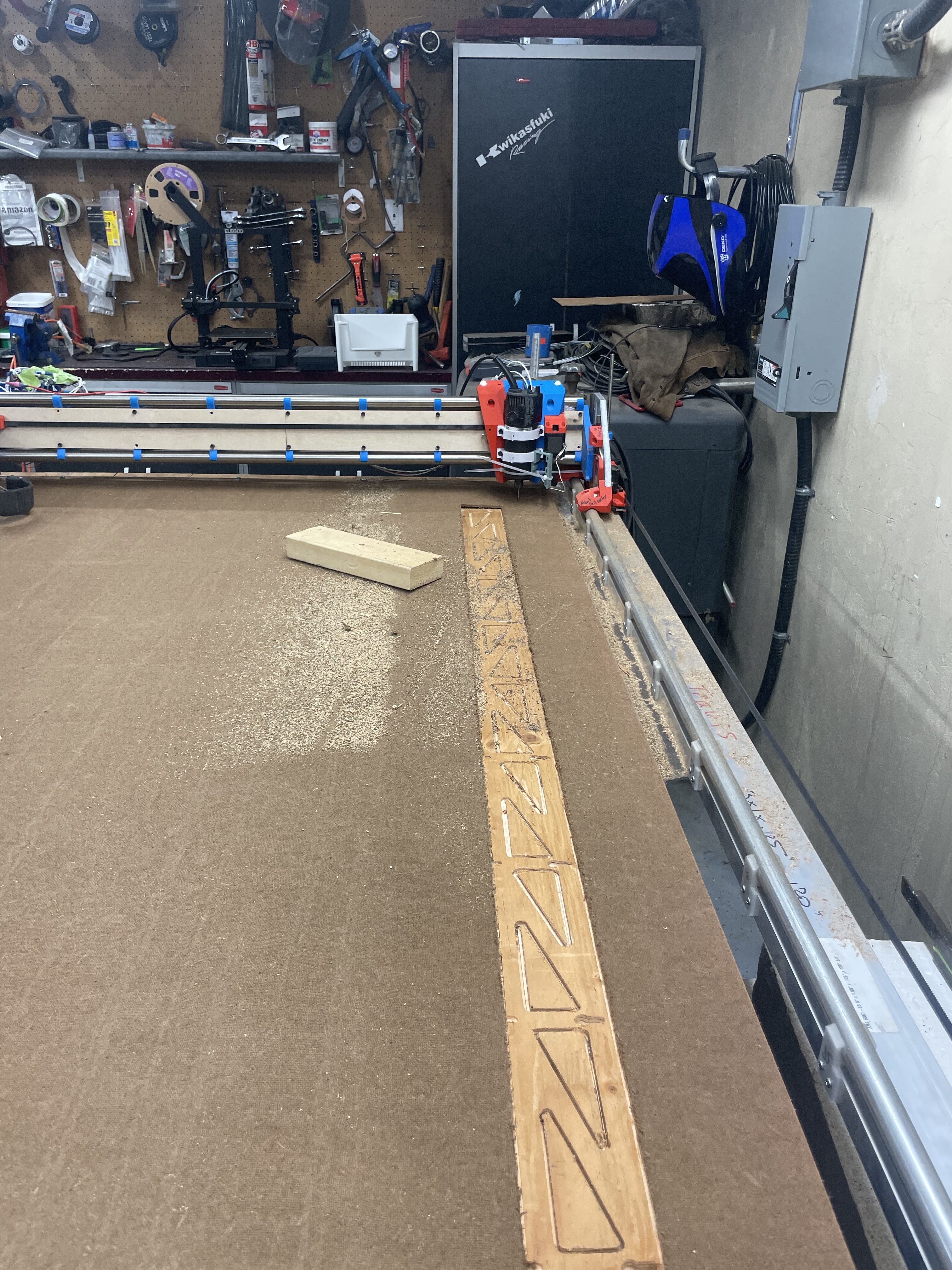
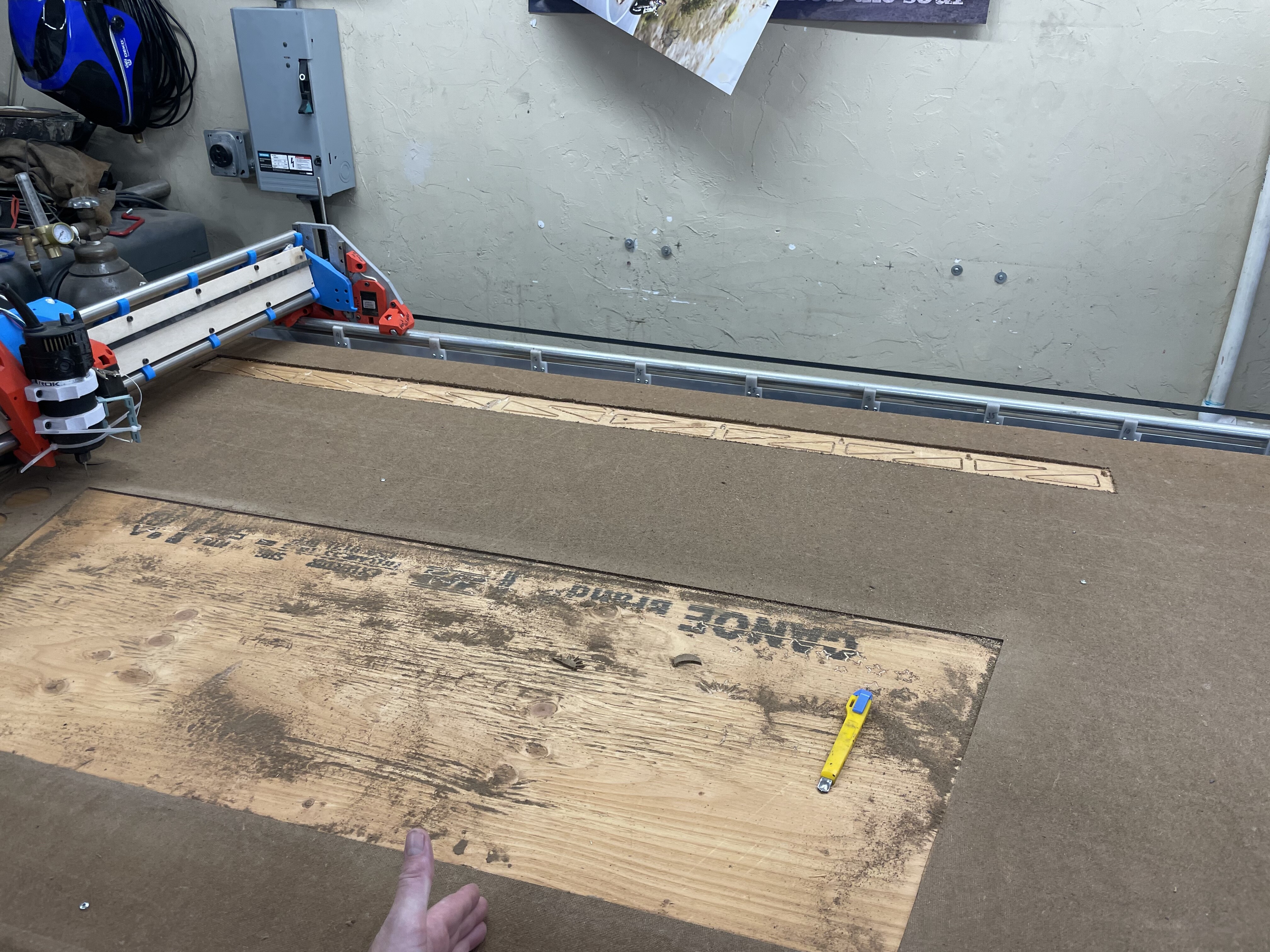
Did my first cuts with the table pretty happy with how flat it is with not really adjusting much yet. It’s a 2mm variation on a 8’ span.
I did have a failure well a couple first one was I think I got the wrong stuff for strut. And didn’t notice until I got home from lumber yard.
1/8” hard board is very flimsy lol they didn’t have 1/4” ply this time. Ohh well good for practice and dialing in I suppose.
The other fail was not understanding I guess the physics of the bit. The upcut sure will want to lift flimsy sheet up that isn’t lroperly secured. And it will also try and suck said bit out of collet if you don’t tighten.
So I was doing strut and I went to start the outside part path and it sucked bit out. I let the machine finish and go to origin and when I went to re install bit I move the gantry and tried to re align and well that didn’t go well.
I do realize I went about all of this primitive and noobly. Should have set home used end stops etc. and kept steppers locked.
It was still fun and I did learn a lot so that’s a win. Anyways thought I would share a update.
Looks like a pretty normal and standard set of teething problems, to me. Nothing wrong with that, it’s all learning and it’s 100x better to make the mistakes early in the process and on cheap stock. I suspect there aren’t many people who haven’t been bitten by each of these at least once. The upcut bit lifting/flexing the material is definitely one I’ve run into a bunch of times.
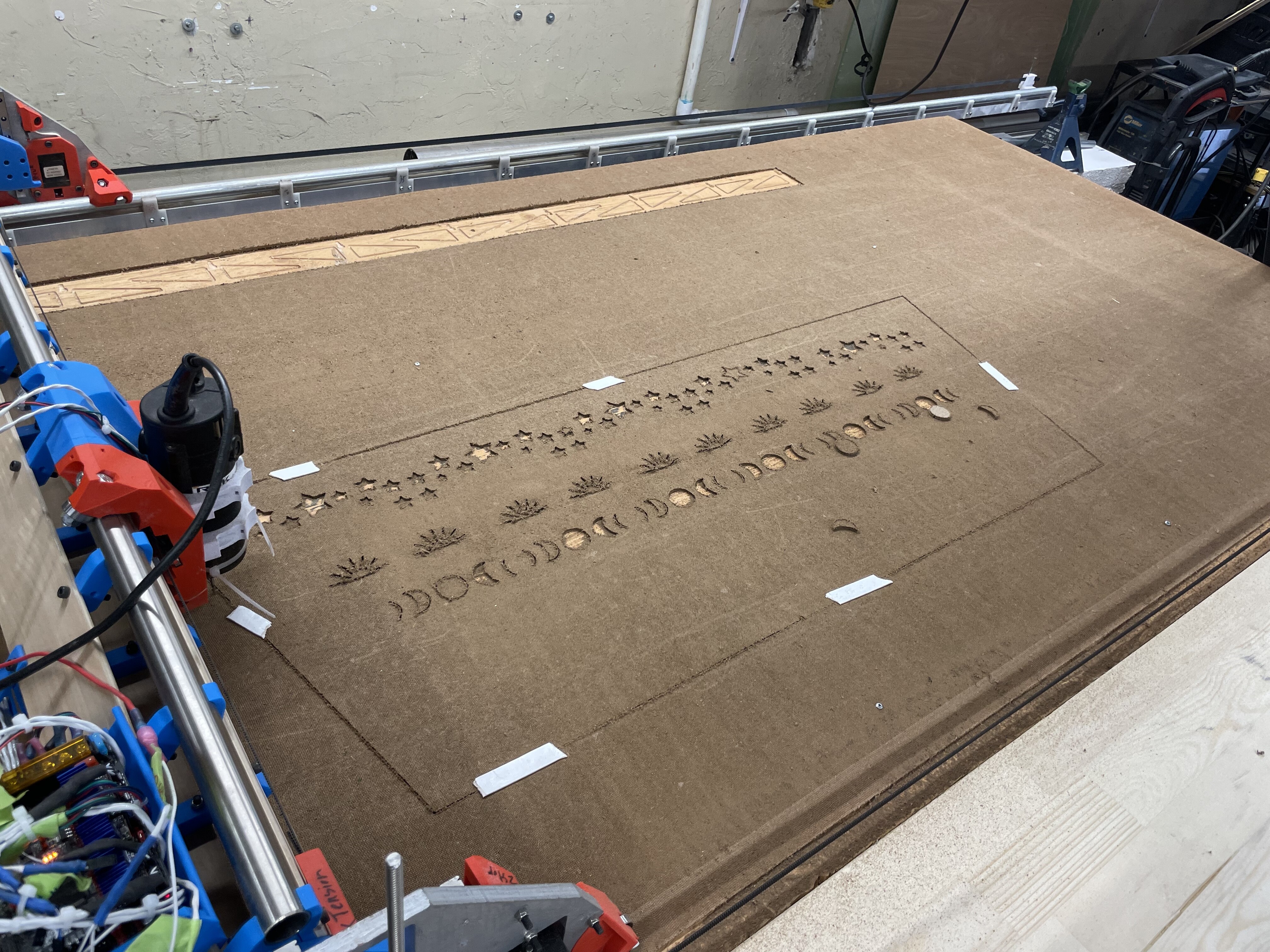
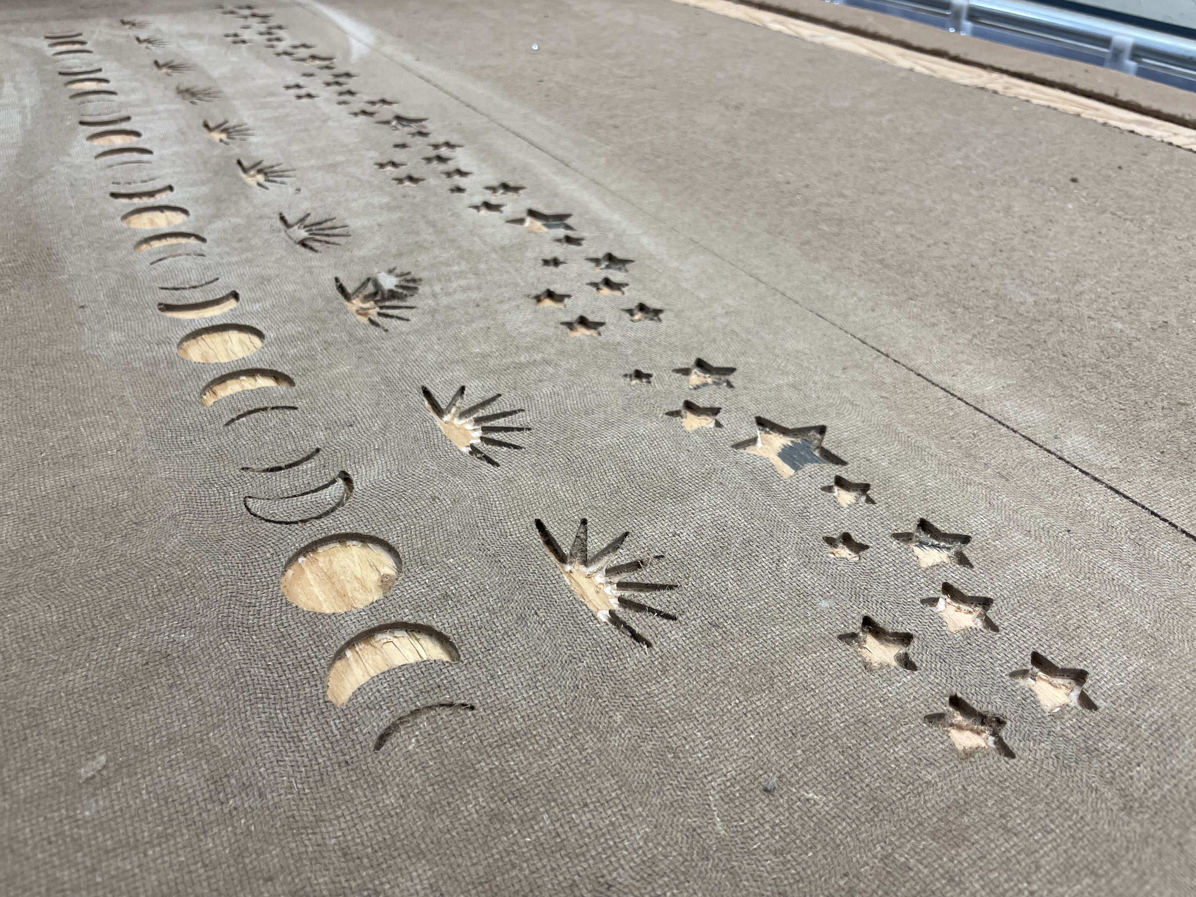
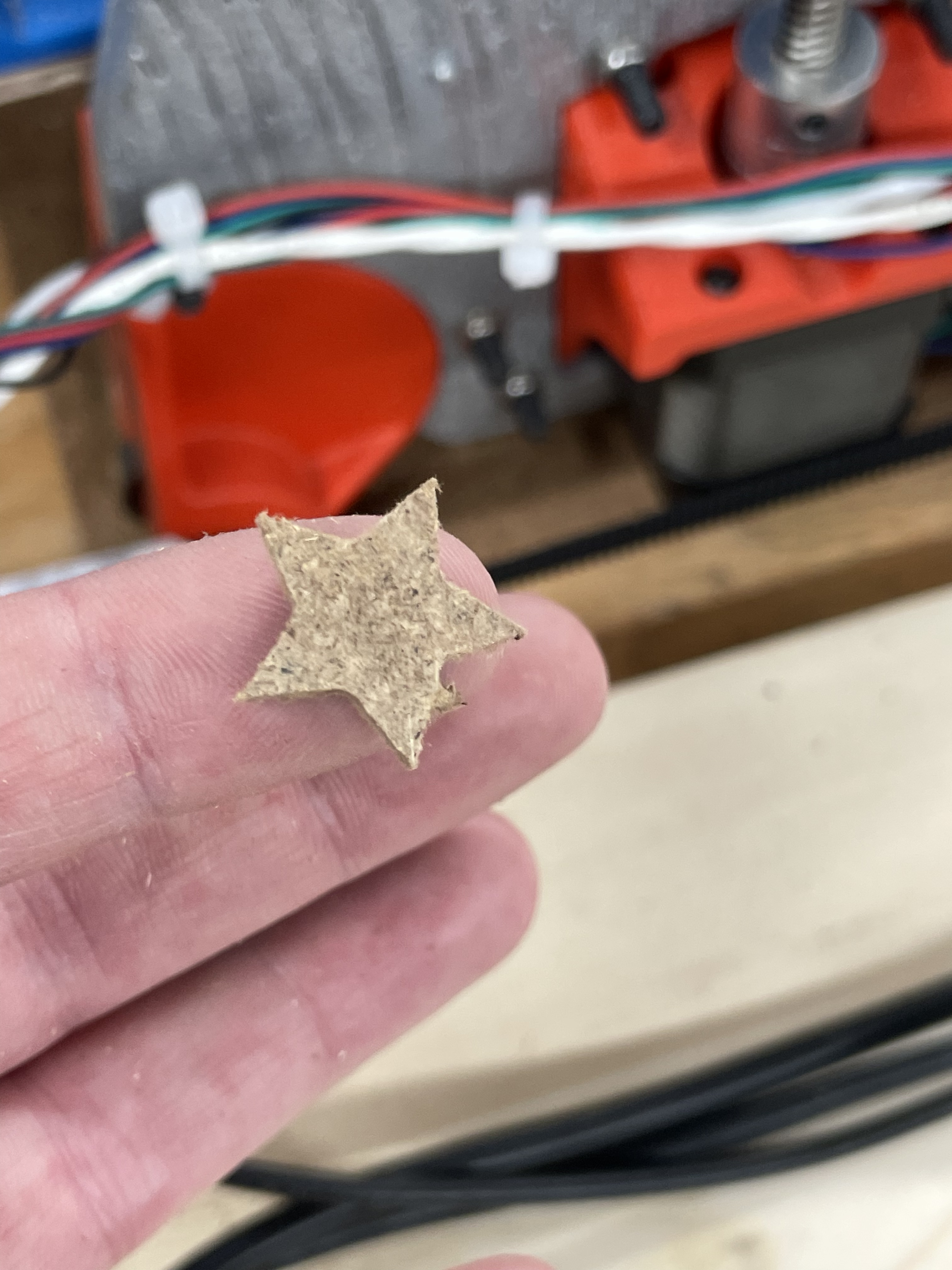
Had success on level ness and cuts. Was happy with the pattern me and my daughter did. Was a fun Inkscape learn but the project was a fail lol. I wanted to turn this into a round cover to hide my ugly bucket hydro setup. But it cracked while I was trying to bend.
Going to try and use this maker case website to help build a 5 sided box
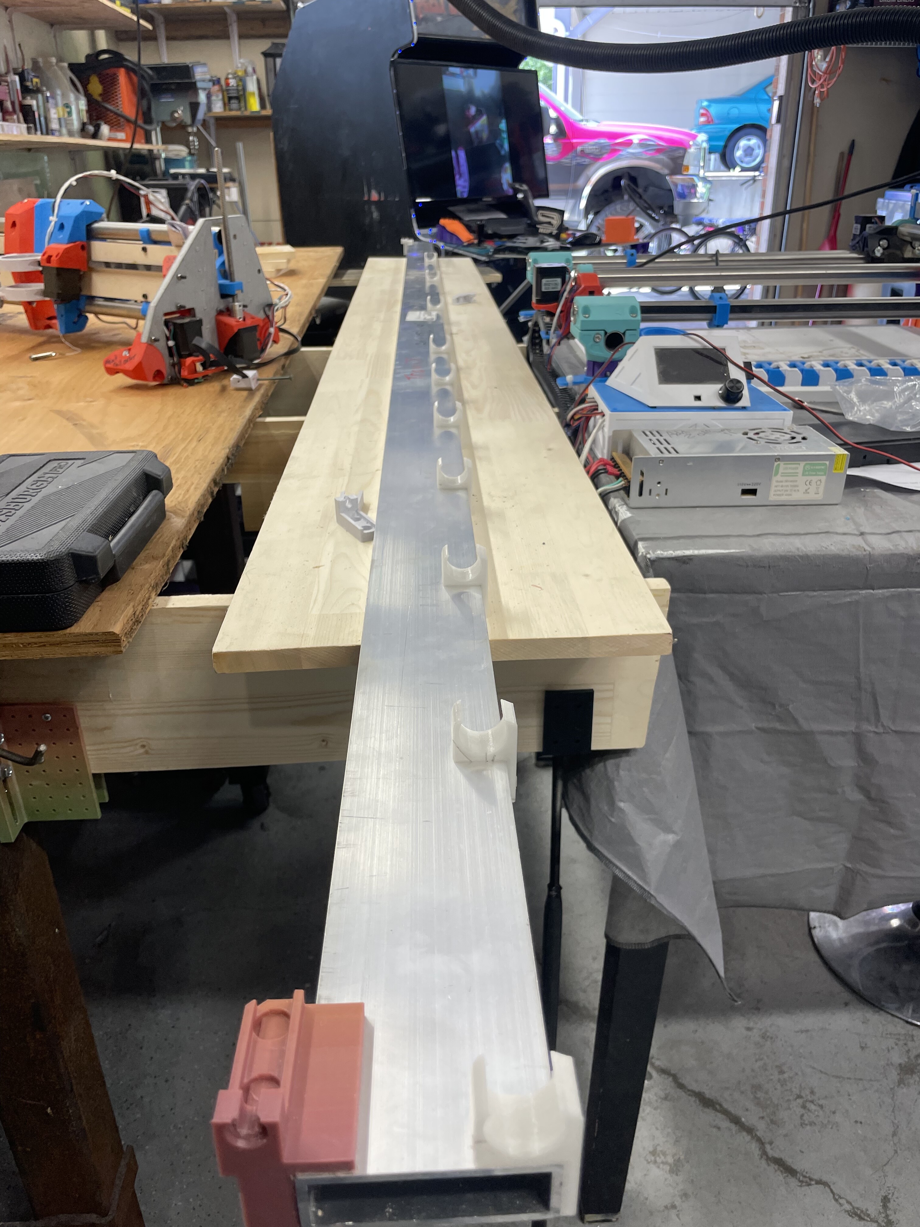
Hopefully I get a chance to widen my gantry tonight.
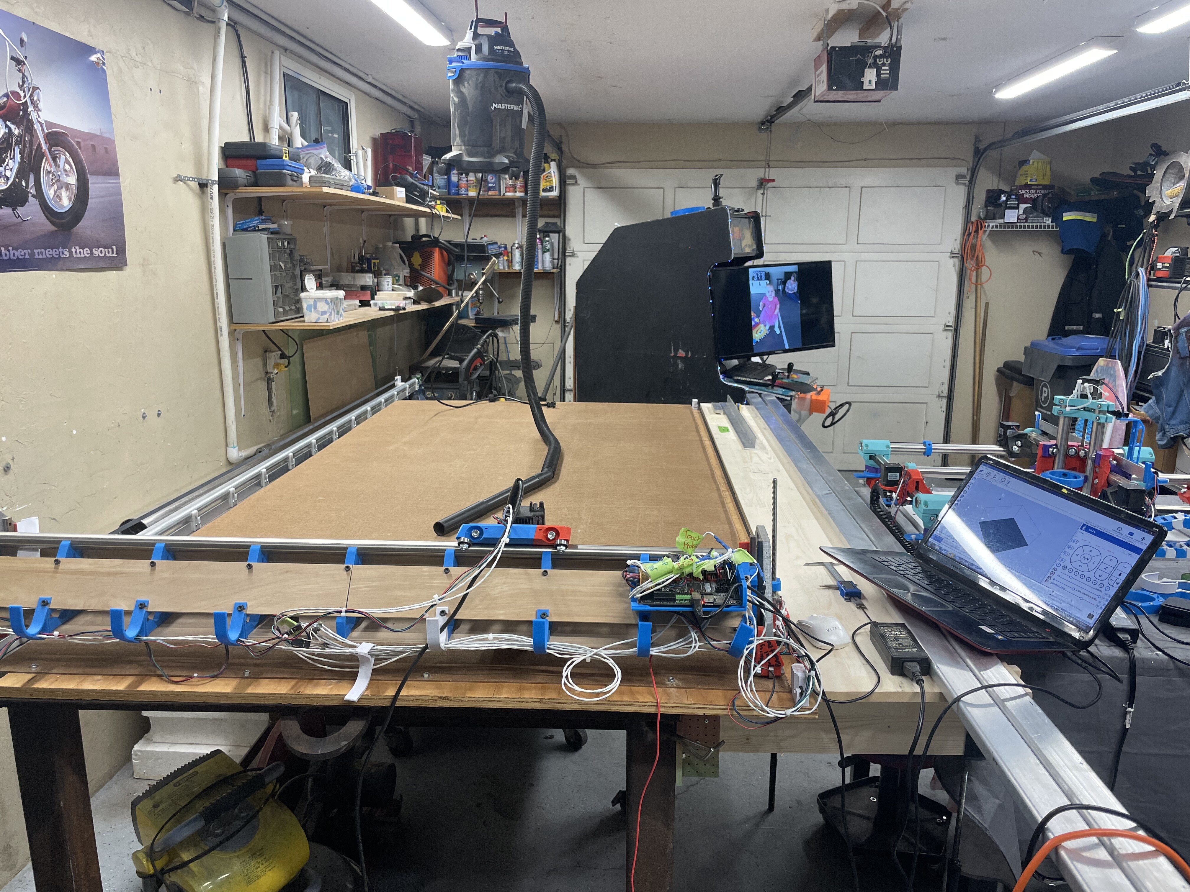
This 60”x120” table is mounted on a 58”x48” table my hand shows where the table ends.