My full designed version is 57" x 112", so just under 5’x10’, and folds up to just under 3’ wide. It features a 4" thick torsion box top, and weighs roughly 500 lbs. You can see my design in the pics above.
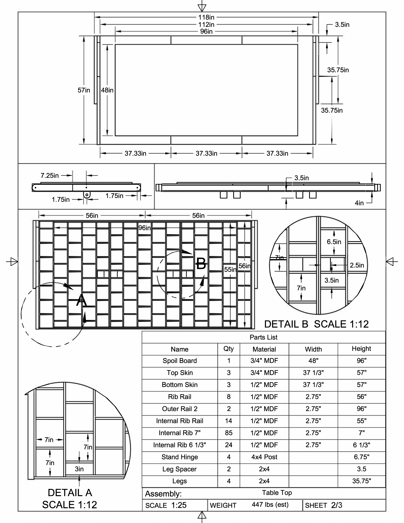
Actually building this beast was a task, as I don’t have a flat surface that big. I ended up putting the 3/4" 4’x8’ sheet of MDF I’m going to use a spoil board on my garage floor and shimming it with scraps until it was as flat as I could get it. This worked reasonably well. After cutting all my MDF sheets to size (which took a couple weekends), I started assembly.
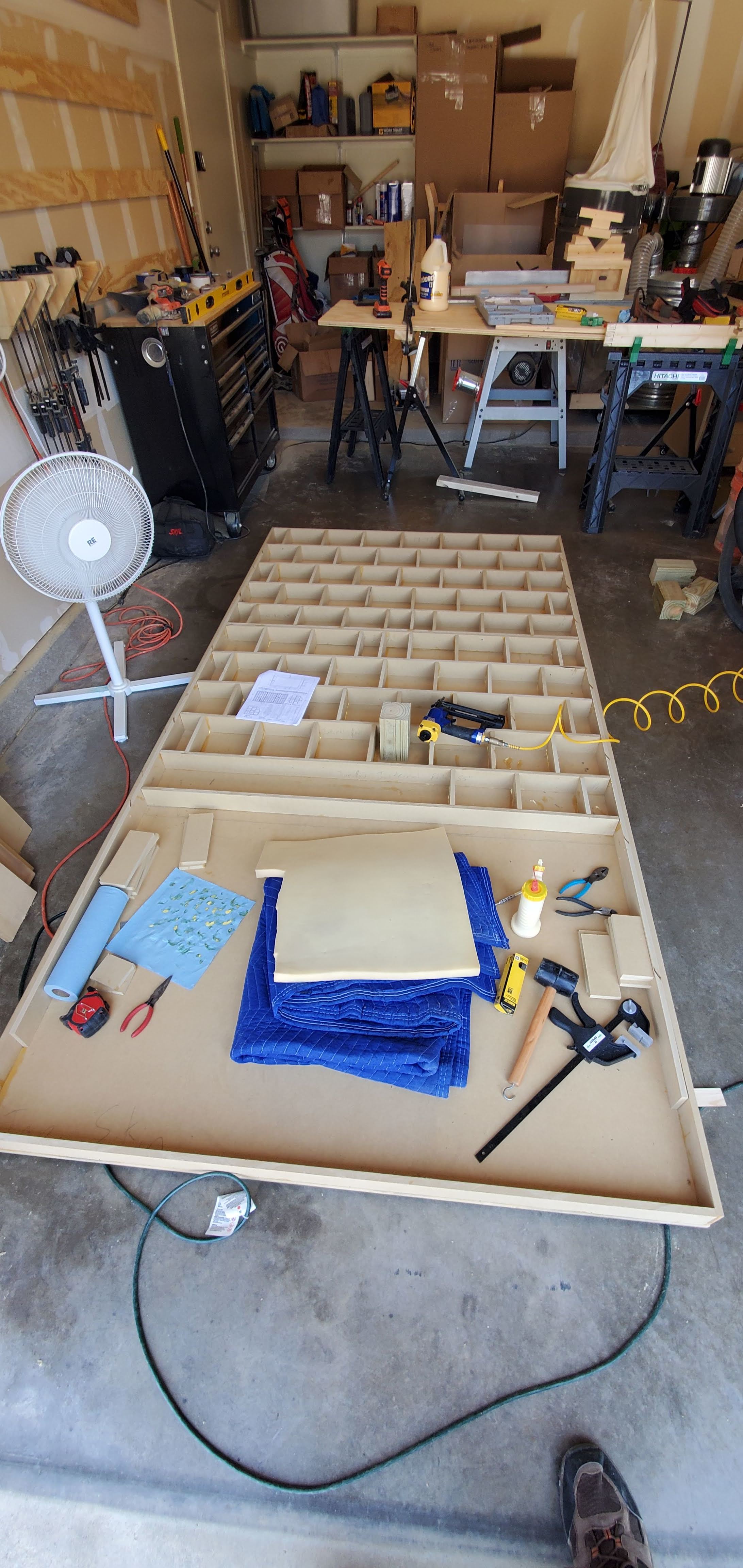
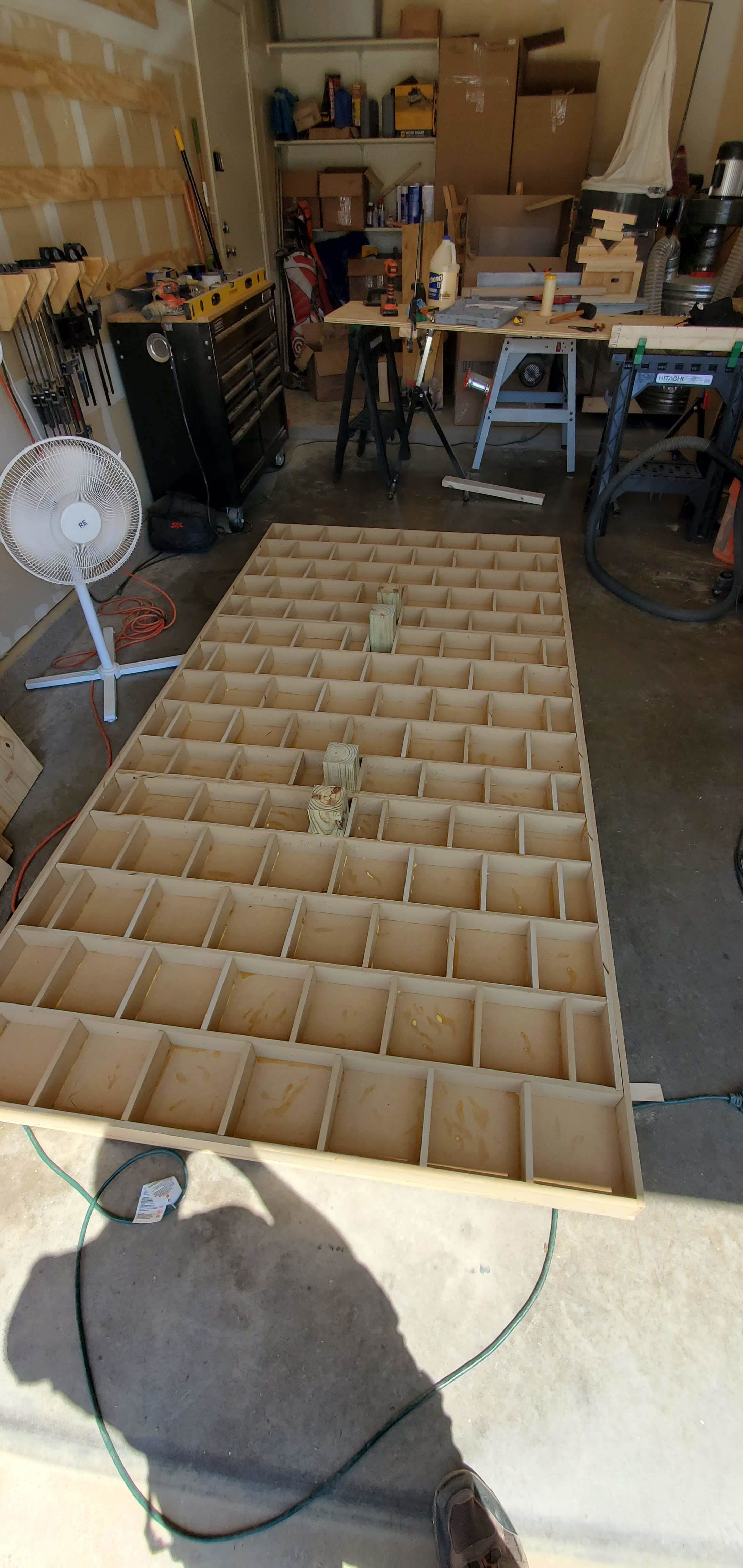
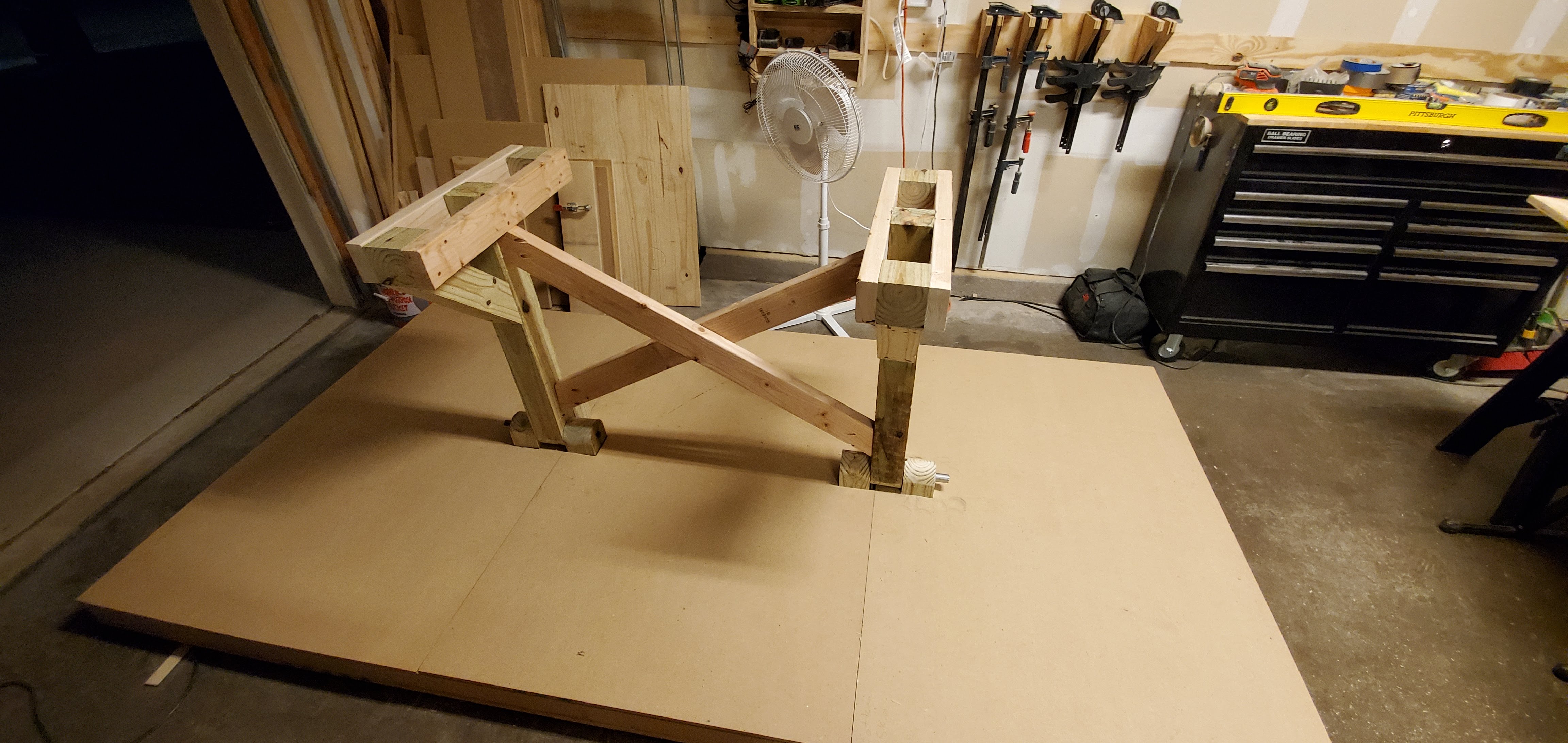
I started with laying the skins down and framing the outside to make sure it was square, then worked on the internal webbing, which took a few days of gluing and brad nailing. I used the 4x4 post to position the hinge posts, which are 1/2" off center to let the table hang a little more positively. Probably unnecessary, but doesn’t hurt.
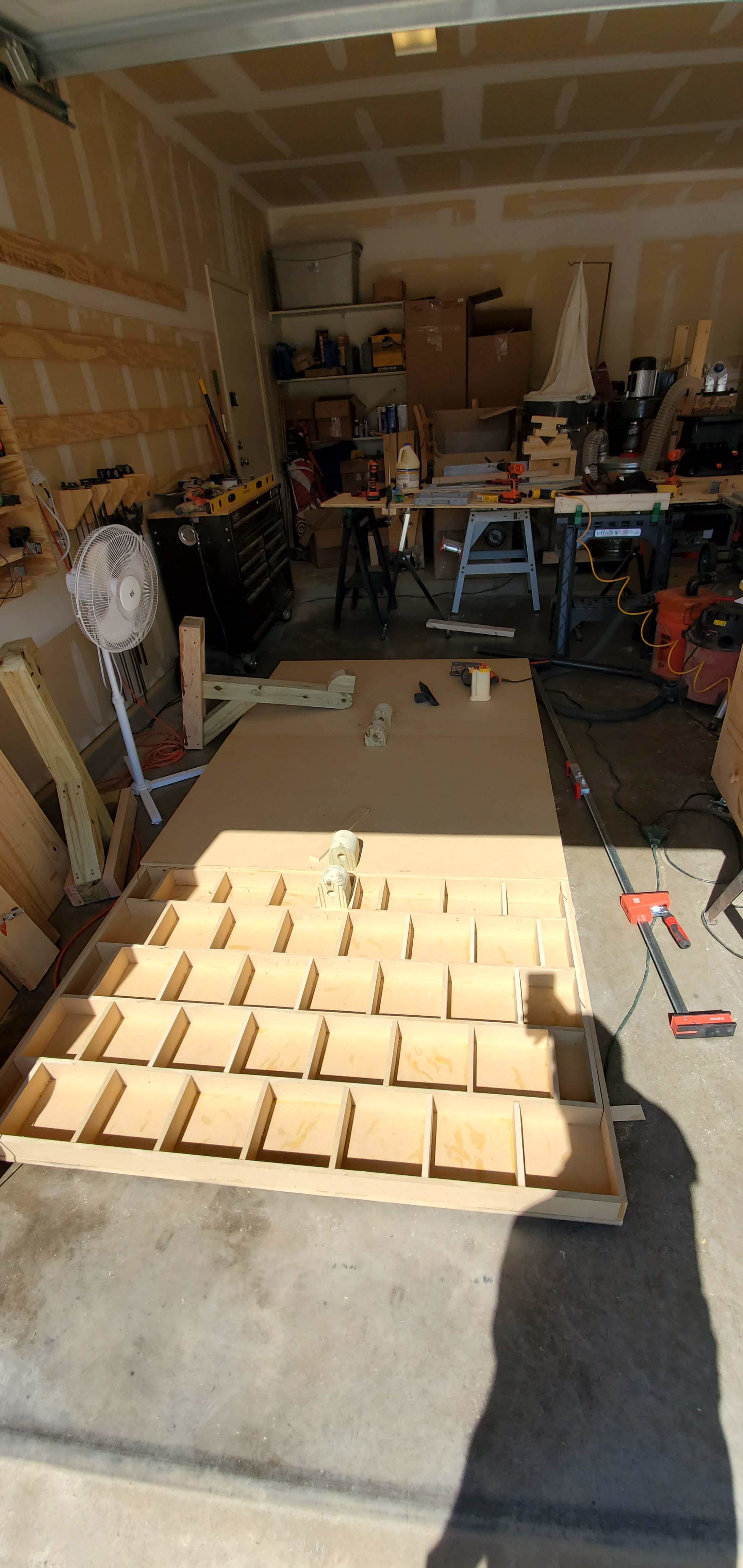
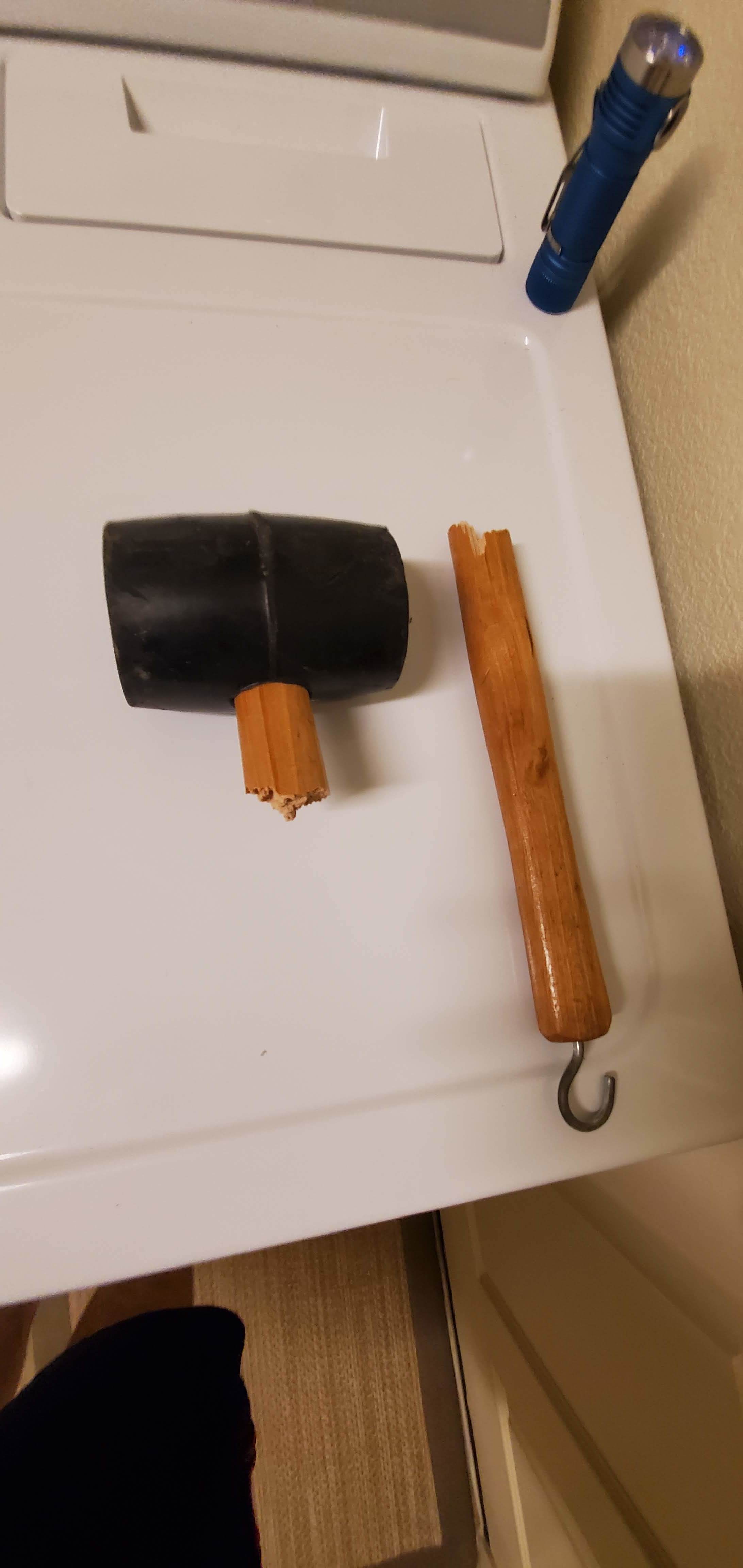
Got the bottom skins on after cutting some holes for the hinge posts. I didn’t cut some of the holes big enough, which resulted in a lot of clamping and hitting with a mallet to try to get the skins in place.
Unfortunately, my mallet didn’t survive the encounter. 
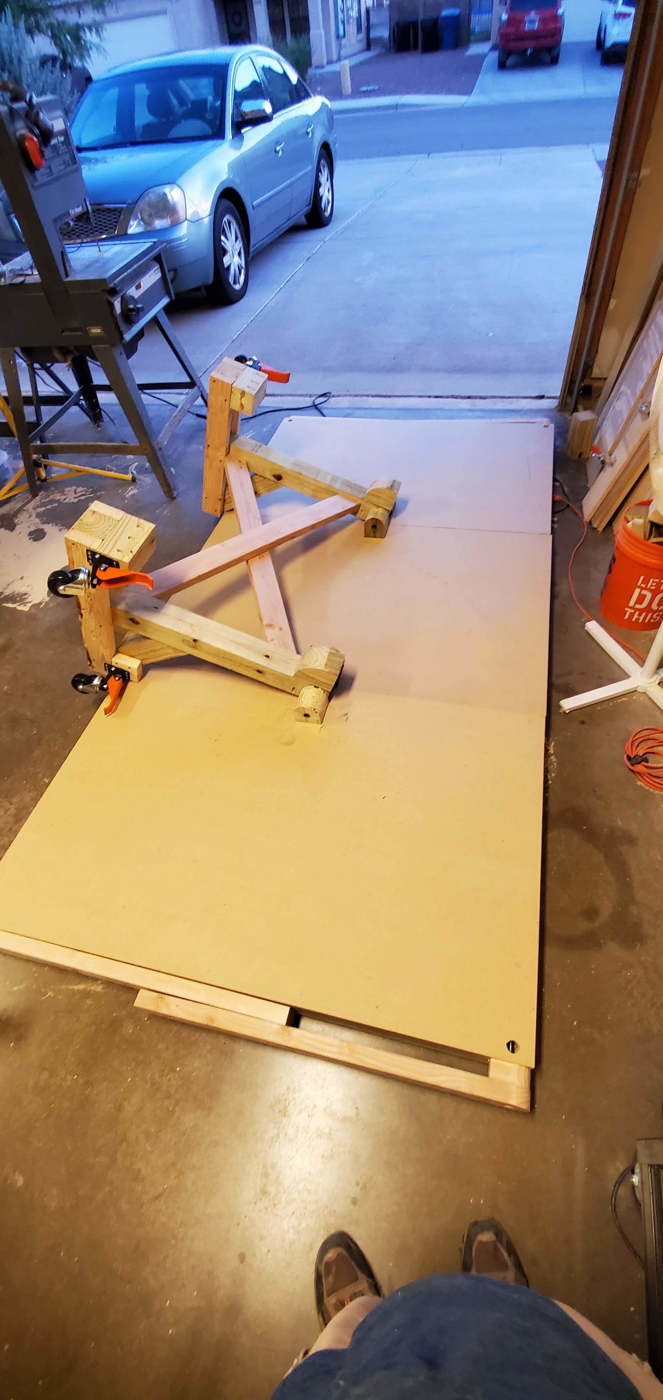
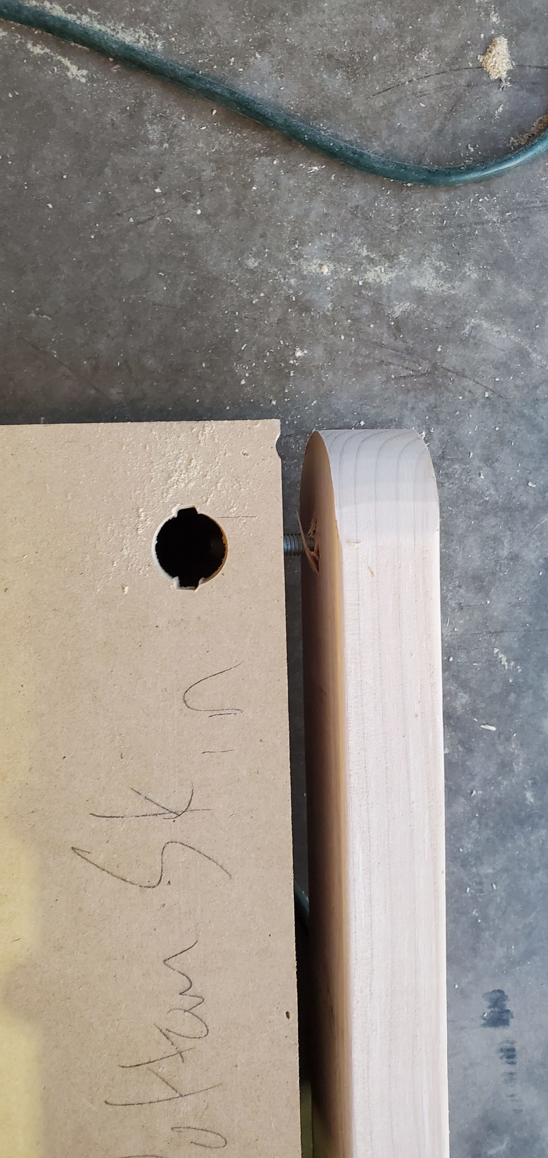
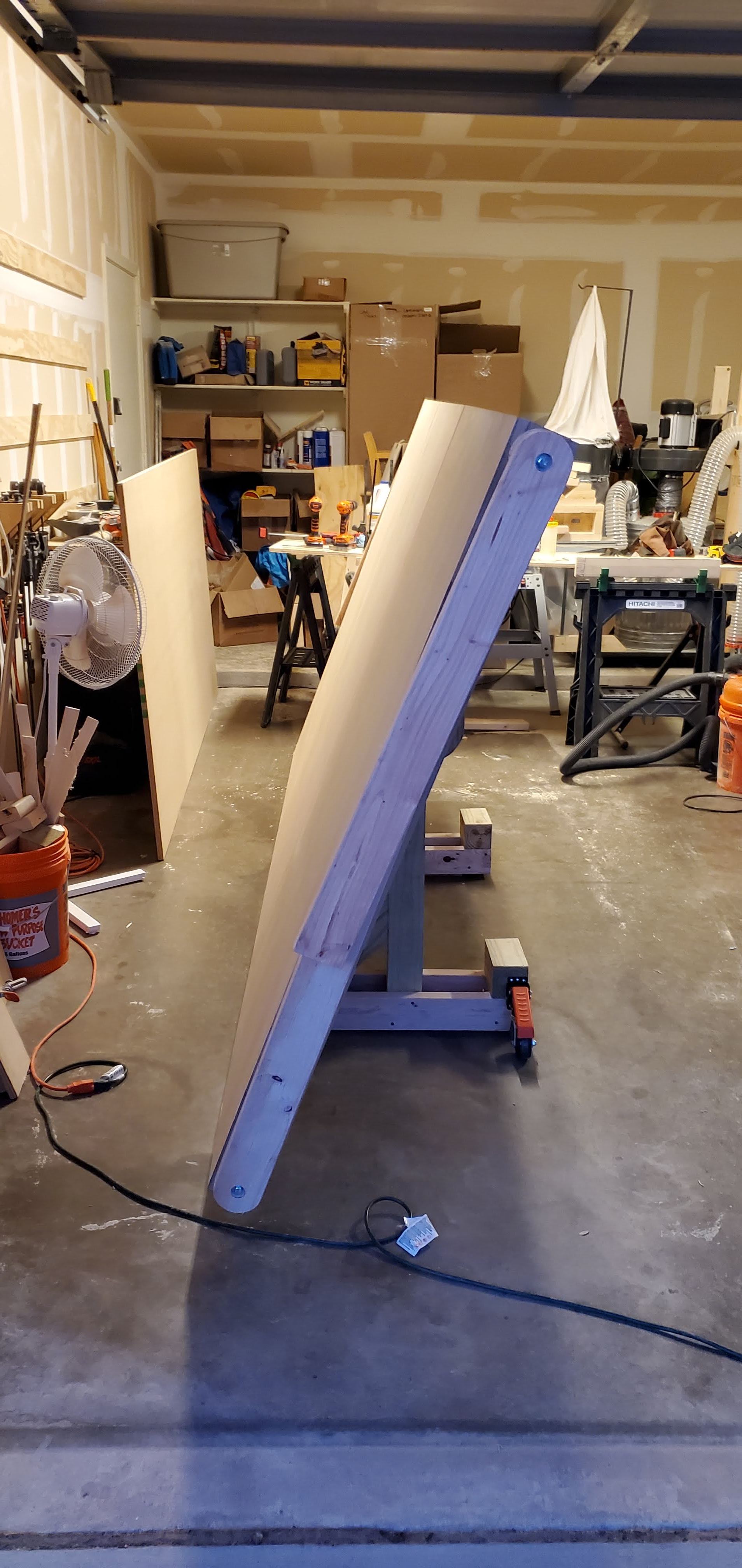
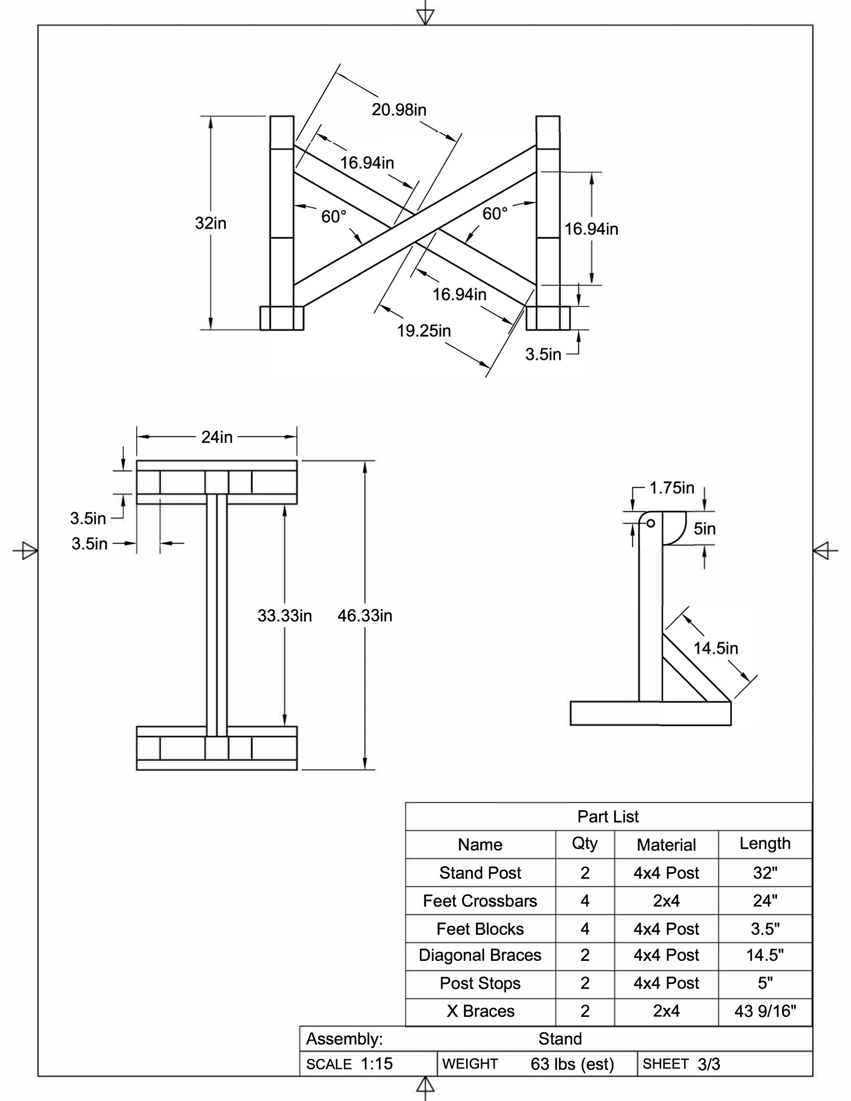
Built the stand and attached to the posts. This used two 1" diameter 12" long tubes, same as my z axis. Getting them through the hinge posts and the stand posts was a chore, as I didn’t get them perfectly lined up. Ended up using a parallel clamp and a lot of elbow grease to slowly force it into place. Luckily, the legs fold smoothly.
The cross members were actually fitted after I had the stand attached, as I didn’t trust that my distances would be exact. This worked out pretty well.
Attached the outer legs with some carriage bolts, drilling a hole and filing a bit to get my wrench in. when these are folded down I can shim them to make sure the top is as flat as possible. I also added retractable casters to the base to allow me to move the table easily.
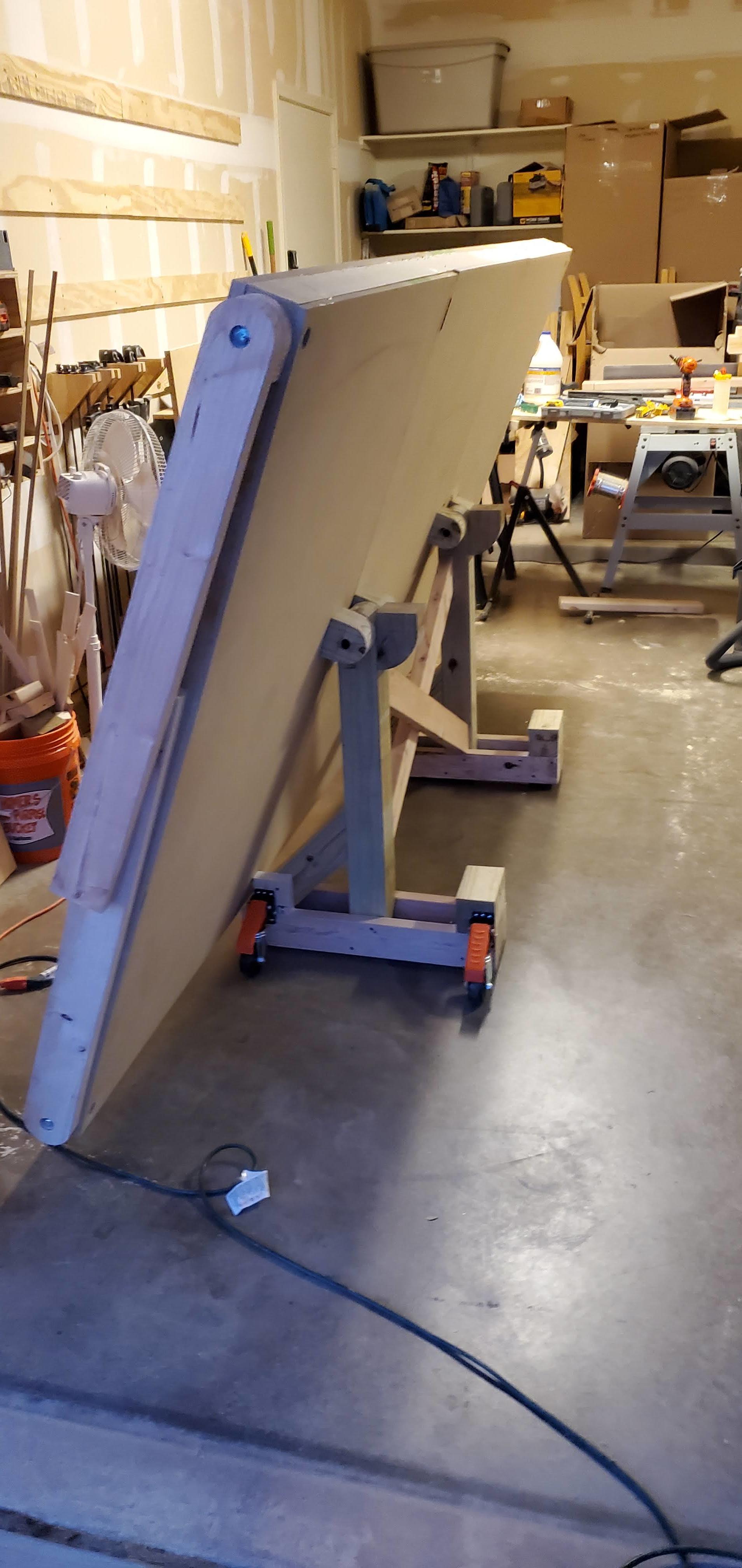
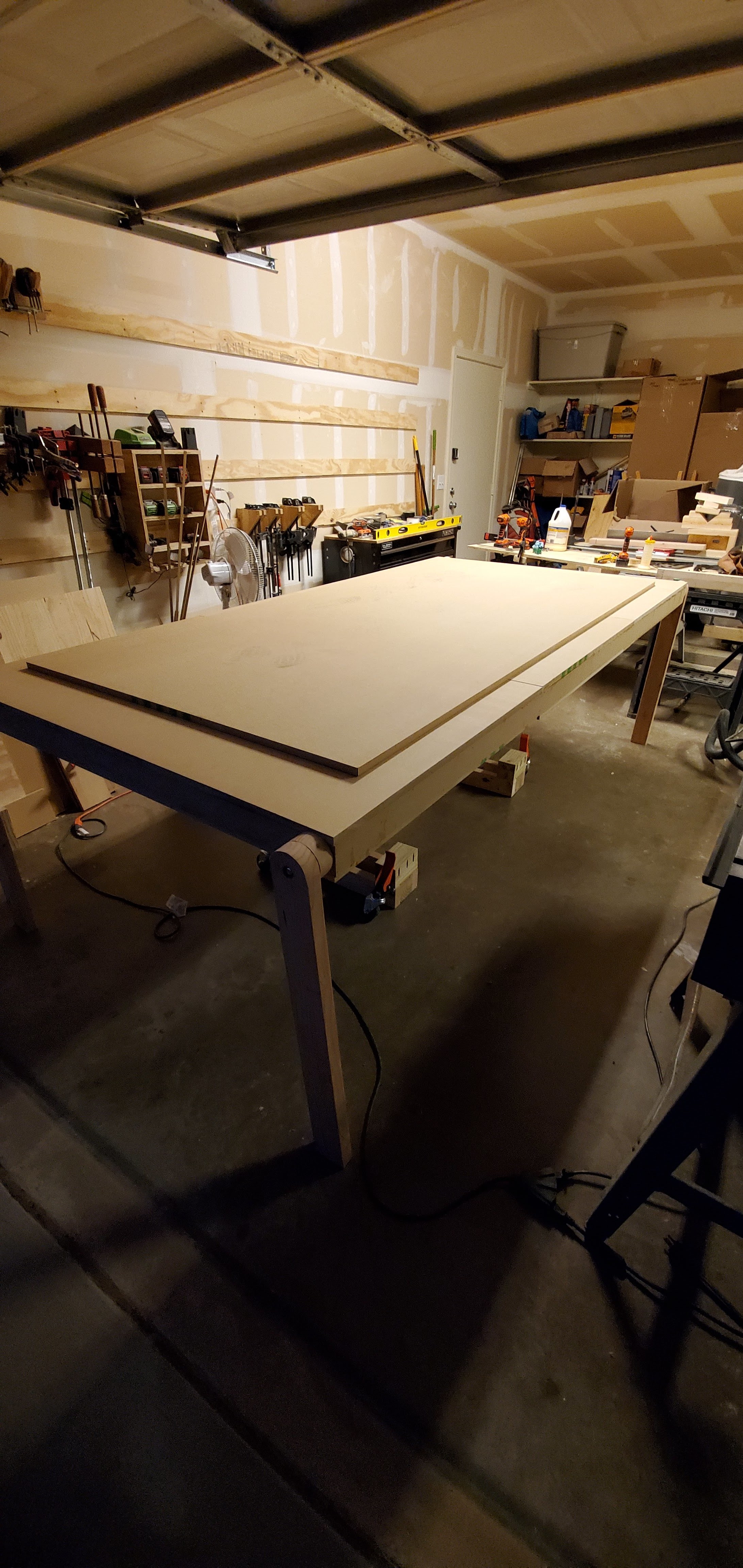
Got the table flipped up! luckily my wife and I were able to manage. The retractable casters work quite nicely, and the whole table is very stable with all of the legs deployed, yet easy to move with the casters up. I can deploy and retract the casters with no difficulty, which was something I worried about.
Spoil board added, and ready for the actual CNC!
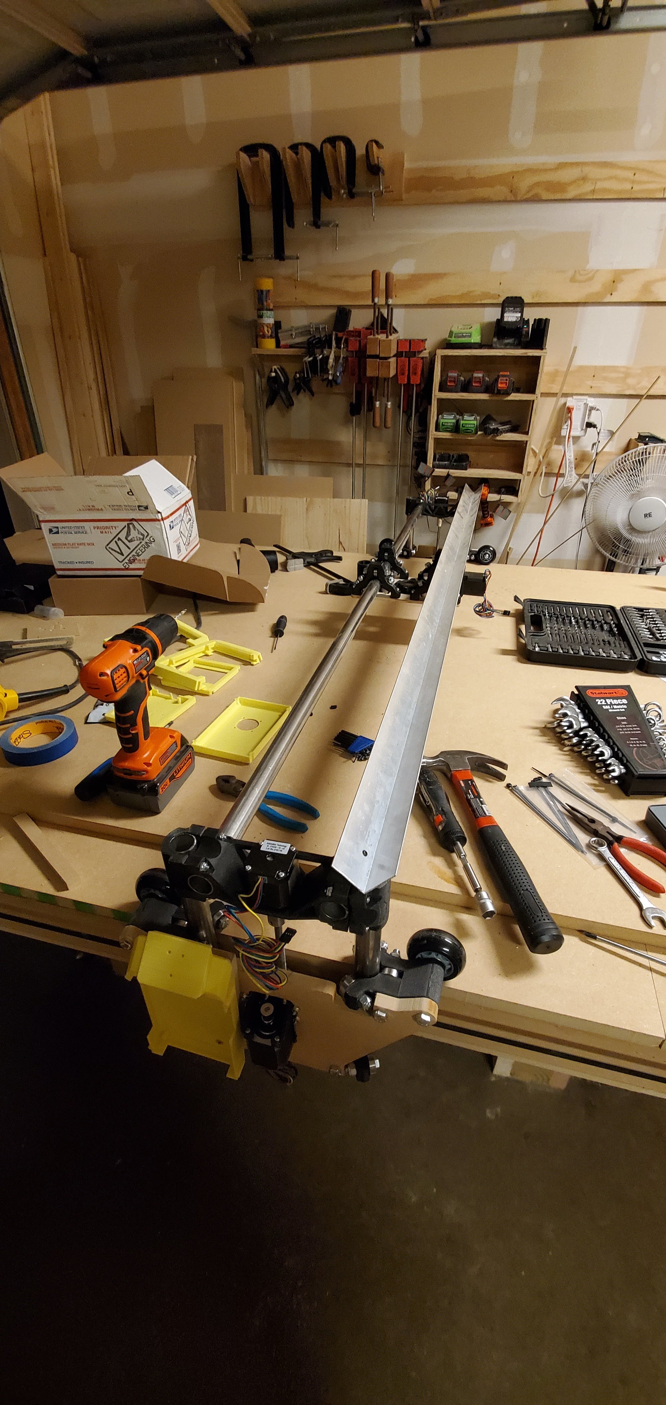
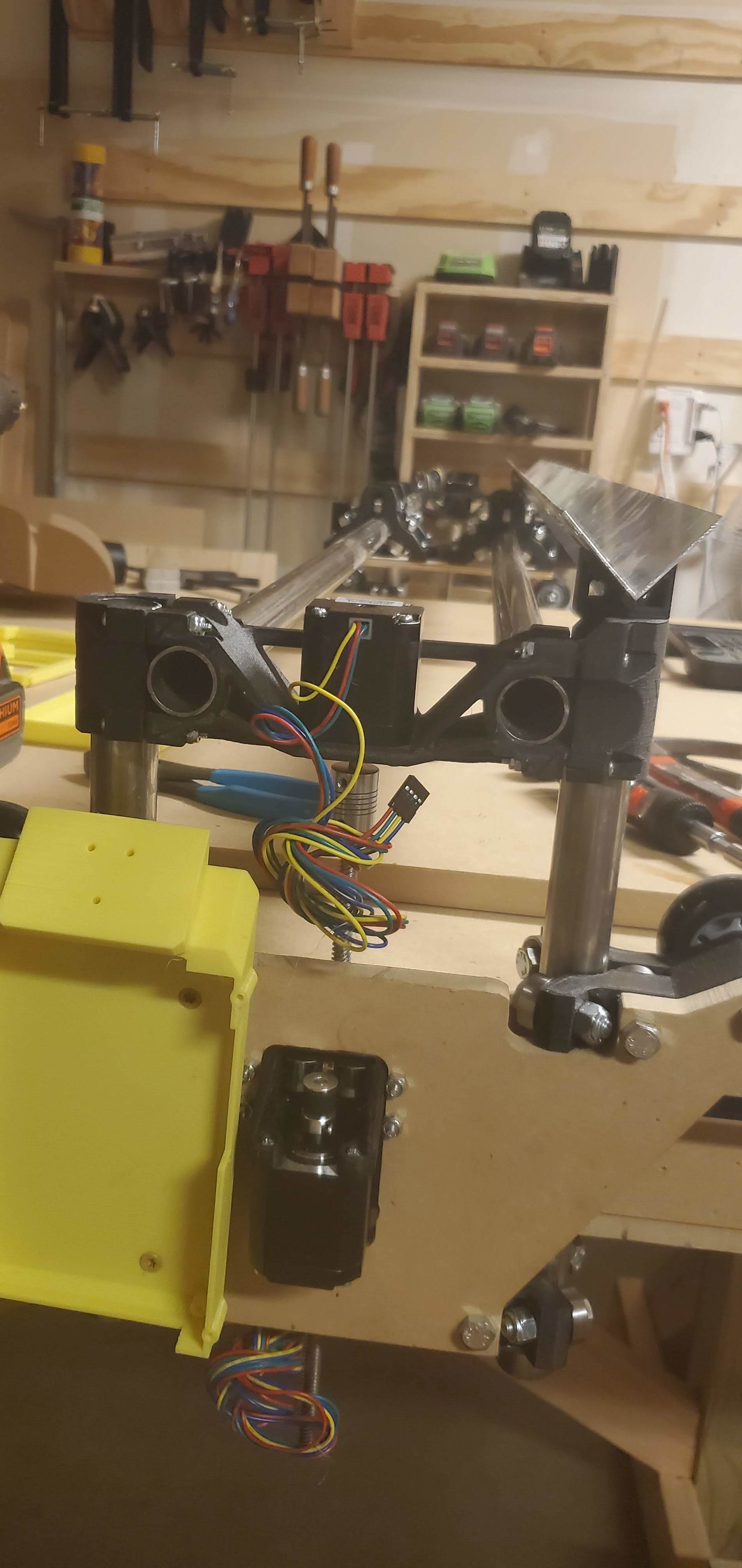
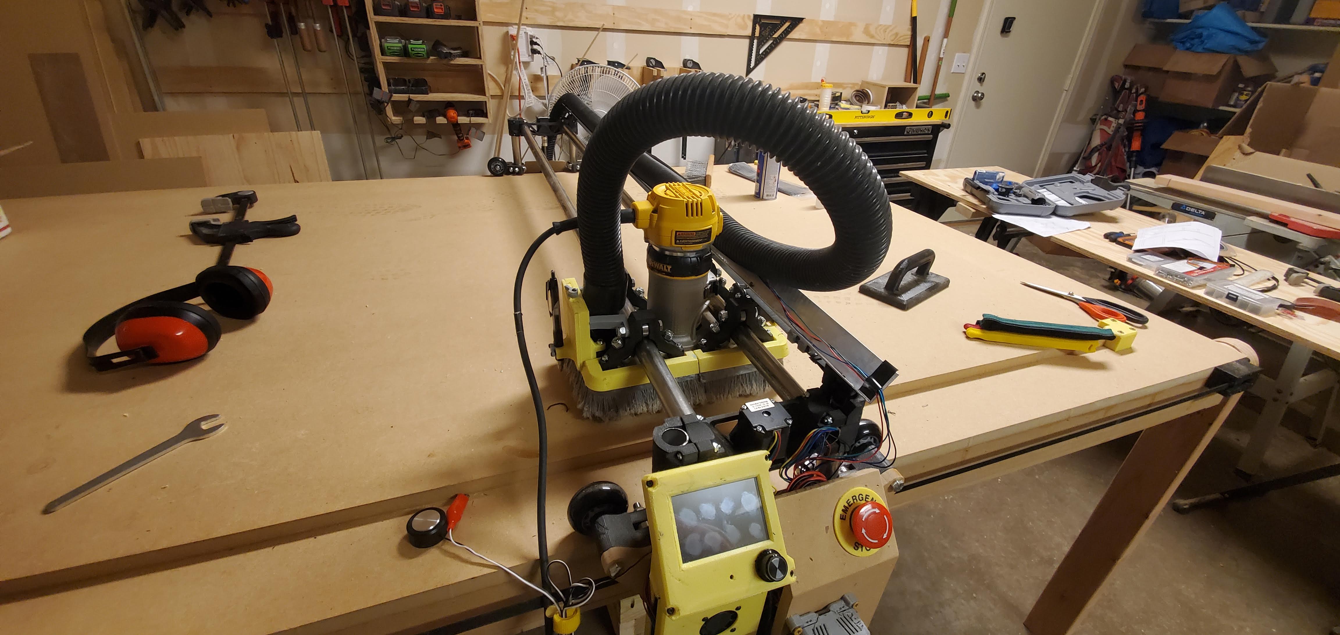
This is where the lowrider2 currently is at. All my parts were printed myself with black carbon fiber polycarbonate or yellow PETG for some of the less structural parts. I also printed an adjustable tension block for the Y axis.
So that’s where I’m currently at. Next I need to assemble my dust boot, attach the router, and do all of the electronics.
This shows more clearly my question, are the end caps on the z rails (I think they’re called the xz parts) supposed to fit flush with the Z rail? I think my rails aren’t quite parallel, but I’m not sure how to actually adjust it to get them parallel and allow those parts to sit flush. Does it matter to much? The whole axis can move up and down quite easily by twisting the lead screw, so it can’t be too out of square, but I’m worried it’ll affect cut accuracy.
 Here’s my first page of drawings:
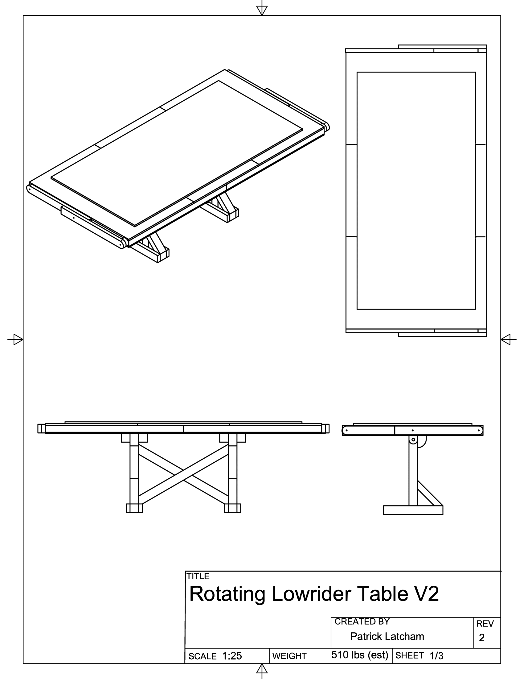
 It looks terrific, I’d really love a report on how the folding/flip up goes after a few months of operation - will you actually fold it away and bring it out for each project? I know myself too well, which is why I built a small version until I iron the bugs out.