The SCARA is based on a scaled down remix of Woobag’s design. I’m using Bart Dring’s TMC2209 Pen/Laser Controller V2.0 (since retired) running Grbl_ESP32.
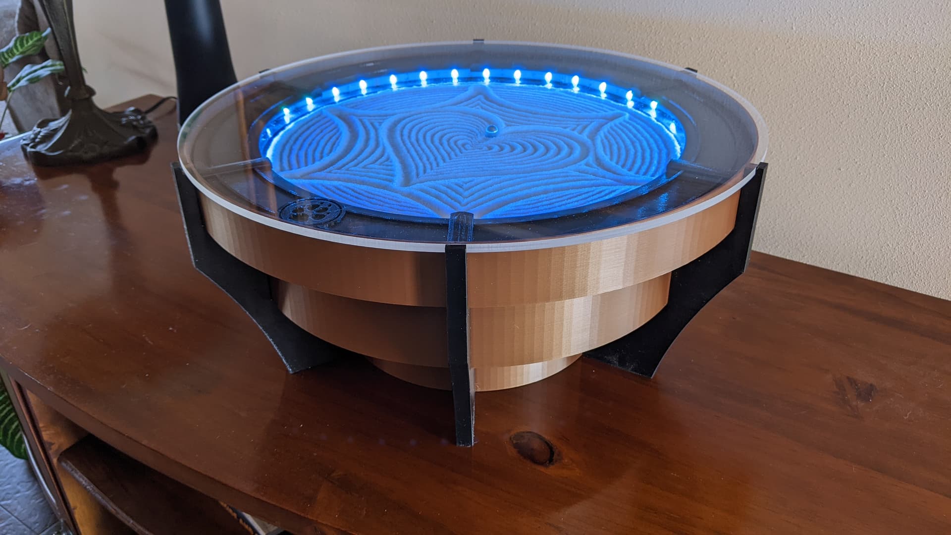
I decided to see if I could come up with an enclosure that could be fully 3D printed on my Prusa i3 MK3S+ printer. I finally arrived at what reminds me of an inverted Devo Energy Dome from the 1980’s (google it). It took about 1.5 kilograms of filament but I am pretty happy with the results. To fit within the Prusa build envelope, the enclosure is constructed in three tiers with each tier segmented into three or six sections. The vertical walls of each section end with one half of a rounded dovetail shape. When combined with the adjacent section, a full dovetail is formed that fits into the corresponding dovetail slots in the legs.
A few screws lock it all together and it becomes surprisingly rigid. To keep everything aligned and centered, the removable sand/LED tray registers on the upper tier screw heads and the decorative LED mask clocks onto the tray.
I’ll probably have to experiment a bit with sand types and the sand substrate. Drawing a pattern is a little ‘crunchier’ than I would like. The SCARA output in Sandify seems to work perfectly (you can probably remove the ‘experimental’ qualifier).
It looks really good. A smaller table has a lot of advantages in terms of total commitment and time to finish the patterns. This one has a very good finish.
You’re right. The experimental comment is not needed.
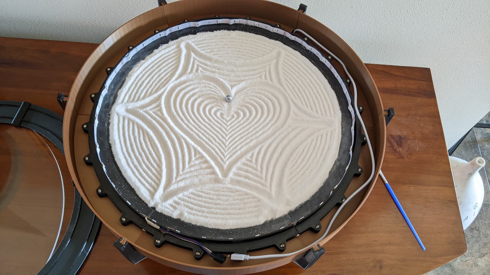
The sand substrate is 3mm plexiglass sandwiched between the black 3D printed segments. I agree…the LED’s need to be more recessed. I would like to come up with a way to reliably secure the the 6 upper and 6 lower segments without using so many (24) small screws and nuts. If I figure that out I’ll recess the LED’s at the same time.
I have tried replicating it with some different components but I am stuck on the output from Sandify not giving me the result I expect. What are the parameters you use for max radius size (I assume 160 based on design, degrees (I have been trialling different numbers), and rho value?
For context, I am running Marlin on a MKS tinybee, TMC2208 stepper drivers and NEMA 17 motors. I might be a little in over my head.
Unfortunately I no longer have the sand table here to reference so this will be from memory. The radius of the polar table that I used was 158. Make sure that X is the shoulder and Y is the Elbow. When you “Export As” make sure that you have selected SCARA Gcode (Experimental) from the drop down list.
Leave Rho as 1 and units per circle as 6. Make sure your steps are right and include the 3:1 gear ratio. Example: 200 full steps / 1 rotation x 1 rotation / 6 units x 16 microsteps / 1 full step x 3/1 gear ratio = 1600 microsteps / unit. I used “none” for the start and end points. Sandify assumes that 0,0 is at the 12 o’clock position. My design has 0,0 at the 3 o’clock position. The design will be correct…just rotated 90 degrees clockwise. Just add the necessary moves to your start code to relocate 0,0 to 12 o’clock. Test as follows:
This gcode should rotate the shoulder one full rotation:
G92 X0
G1 X6.000 F60
This should send the elbow around one half of a rotation:
I finally have the mechanism moving but I am assuming that I have jumbled up something in Marlin.
I can get the machine to move to 12 o’clock with G1 X1.5 Y4.5 (from home) and set it as 0,0 with G92 X0 Y0. When I ask Sandify to output to the centre using the point function it moves it to 9 o’clock (which I would assume should be G1 X0 Y3). Any idea where I may be going wrong?
I used GRBL so I am not familiar with Marlin. I would suggest asking Jeffeb3. He is the creator of Sandify and is probably the best person to help you.