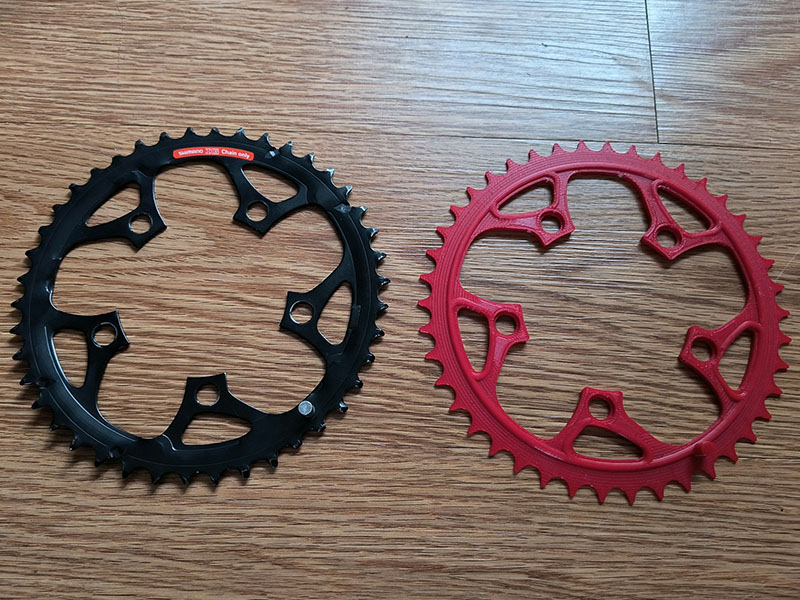
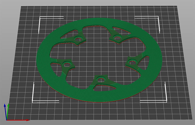
I have an old Trek 930 Mountain bike from the 1990s that has a bad outer gear. This model has 3 front gears & living in the mountains, I don’t really need that gear. I designed a replacement gear for this back in 2015 to see if it would fit on my bike, but plastic obviously would not work for this. Now that there are more options for online 3d printing out of different materials, thought I would revisit this after my wife decided to start riding again & had to replace her 2005 Trek bike since it needed too much money in repairs. Using this site: Online 3D Printing Instant Quote - JLCPCB this part would cost $48+$26.63 shipping out of 3D printed 316L Stainless steel, $11.70+16.76 shipping out of PA12-HP Nylon or $7.80+16.76 out of 3201PA-F Nylon. This is still probably too pricey for me to have it done, but wanted some of the experts on here option of this. I will probably just keep the bike as it is or replace the bike if I has some major problems. I do kind of like the newer mountain bike models that only have 1 gear on the front. I have it winched to the top of shed, so have to get it down soon to really test it. Here is what my gear design looks like. Somewhere along our trip in 2012 when the bike was on the car, someone seems to have bent that gear with a wrench. It also has several teeth that are worn down & not relate to the bending part.
Very cool project!
My unscientific and uneducated brain is telling me you’d want the gear to be a harder material than the chain members that come in contact with it, right? Do you know what the original is made from?
Nylon is pretty ductile on its own. It’s tough but not very rigid without a reinforcement additive like CF or GF. Even then I’d imagine it’d flex and warp since the part is so thin.
Stainless, maybe? Not sure how the chain would interact with it. Also don’t gave any experience with SLS printed metals.
Maaaaaaaan, I’d put that plastic gear on there just to see how far it can go. I don’t have any experience with nylon under these kind of conditions, but being MUCH softer than the chain…I wouldn’t expect much longevity there either.
I don’t recall if you already have a cnc or not, but these things can cut aluminum without much trouble at all. Way cheaper to get some plate and give it a go, even if you scrap a few pieces along the way. Aluminum will not be as durable as stainless steel, but it gets used on some dirtbike sprockets so it’s good enough, and you can make a LOT of aluminum gears for 75 bucks.
This seems like a really cool what-if project, but I wouldn’t expect any kind of durability out of the printed parts… I know a guy who volunteers a local bike restoration place and they see a lot of used parts. He sees a lot of vintage bikes and the parts are not super expensive. Some are near new or new old stock. Maybe I ask him to look for one and I’ll ship it to you? The new bikes are considerably more expensive now.
How many teeth are you wanting on the ring (30,36, 40, 46, or 42* what I count from photo)? I tried replacing the derailleur roller on the rear with a 3d printed PETG idler pulley and it didn’t last long.
I’ll look in my parts bin and see if I might have something. I realize the point here is the technological solution, but sometimes a low tech low cost solution is very robust.
I am not sure I had thought about cutting it out of aluminum. The gear is only 6.85" diameter & my sphinx CNC can handle up to around 12". I am not crazy about machining aluminum because of all the mess it makes & I don’t have an enclosure around mine, so I probably won’t do that. Thanks for the idea though.
This is a 42T gear used on a Trek 930 bike I bought back in 1999. I was going to ask a friend to bend it in a vice for me, but after looking at the teeth, that didn’t seem like a worthwhile idea. A used replacement would be perfect. Thanks for asking for me.
Also does anyone know the dimensions for drawing the teeth of these gears? Think I just mostly traced one years ago to get it close as I could not find the mathematics to generate one correctly.
you just need the chain roller spacing as long as you have the 5 bolt crank connectors set correctly, I think standard bike chain rollers are on 1/2" center - spaced pins, so as long as you get the teeth to space for 1/2" chain pitch, you should be good to go.
I found this page that gives me a good idea of how to draw them. Mine is 1/2" chain pitch. How to Draw a Sprocket Gear : 5 Steps - Instructables
My original drawing is only off by 0.95mm on the inside arcs of the teeth. The white teeth in the drawing are the corrected ones. I used one of his teeth from his 58T drawing & matched it to my 42T Gear. I might just make a plastic blank with circle to represent the outside teeth & use it as a chain guard.
Cool project, curious how shrinkage during sintering works out. Whether they figure that out automatically for you, and/or whether they share details your design needs to account for shrinkage. No idea if they have heat profile/spec used similar to reflow for PCB components.
That is another reason I am not willing to spend $75 on one. It is mostly an exercise to see if there are any reasonably good solutions. Living without that gear is my best option so far. I am not a fast rider anyway.
If you’ve already completed a CAD design, it might be worth checking Send-Cut-Send if you want it cut from a sheet material rather than getting it printed. I don’t know if they could do whatever profiling of the sprocket teeth would be desired.
Gear design is fun*.
*Non-intuitive the first umpteen times you have an engineer explain it to you.


