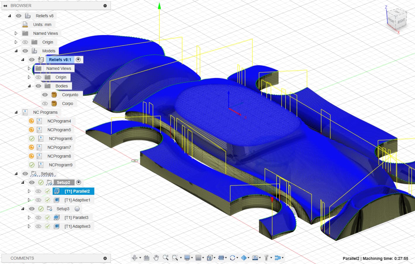
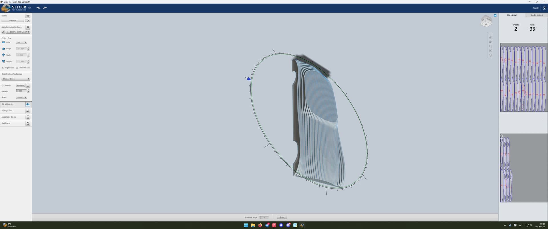
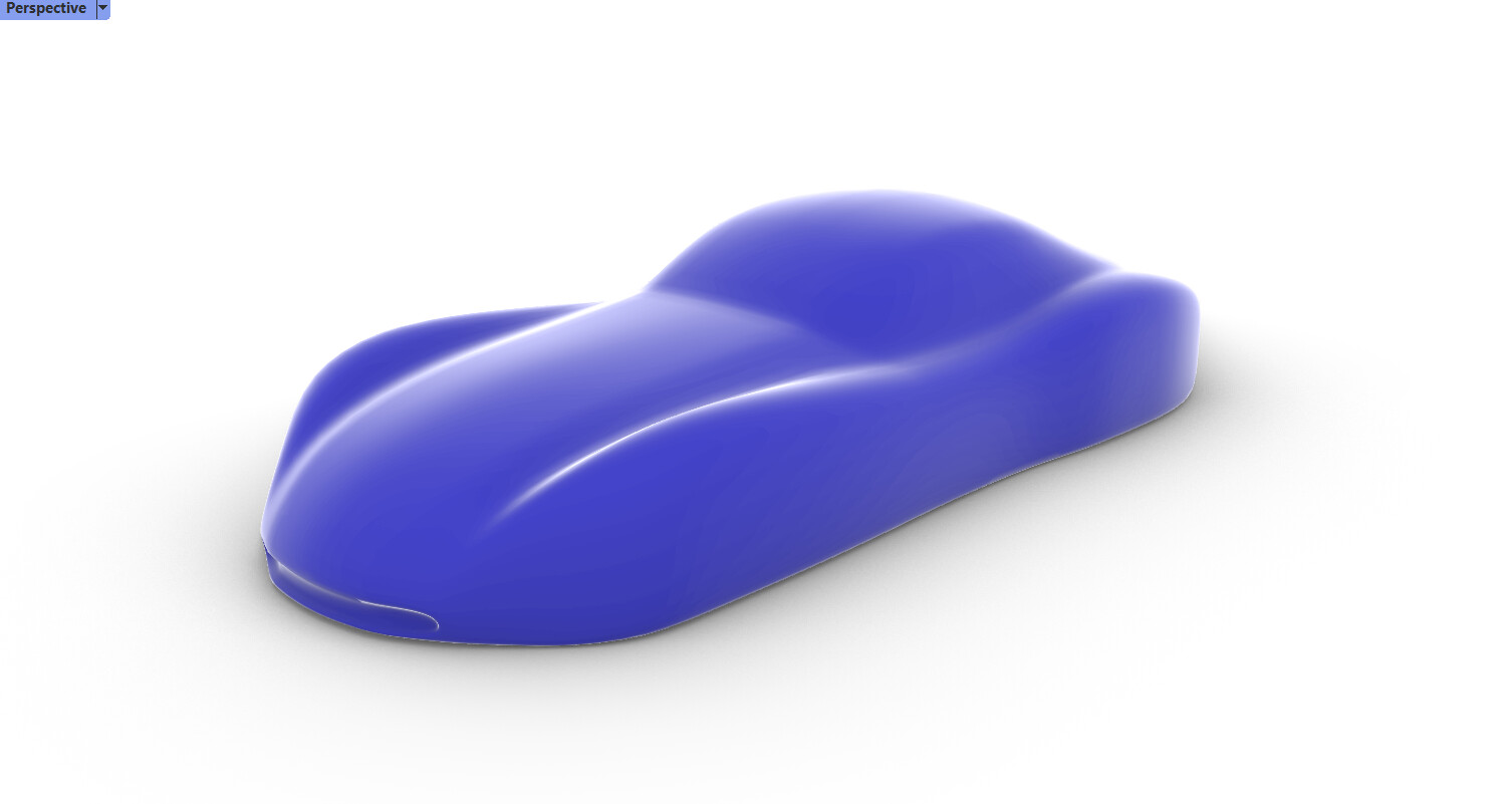
Finally got the machine working and milled a 3D relief of an Arowana fish. Pretty cool and I’m Very satisfied, but now I need to take things up a notch. I built my machine to mill a car I designed and am building (chassis is ready) out of styrofoam. For that, I thought I’d design a simpler model and slice it up into parts and mill that first. And I’m struggling with milling anything but the surfaces. I’m struggling to find the correct strategy to mill the wheel wells and the empty space around it.
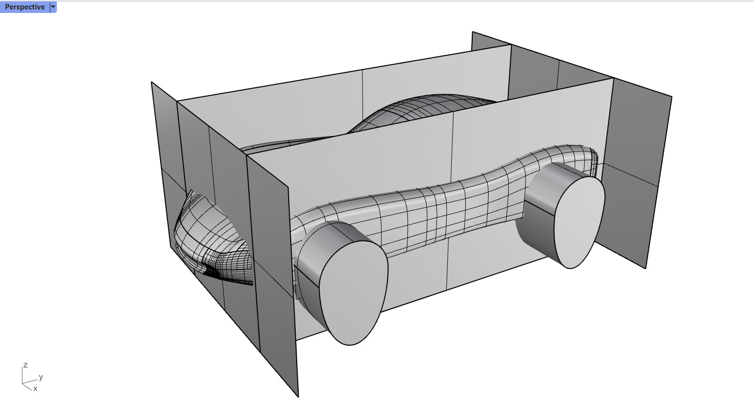
I tried the adaptive clearing strategy but it just doesn’t work. I’m at a loss! Anyone have any ideas? I uploaded the stl (I designed it in rhino) so anyone can have a go at it.
I’m not sure I understand what you are asking. Assuming you want to mill what you have in the image, just do a 2D Contour cut using the profile at the bottom of the model pieces. I assume you will use double-sided tape as your hold-down method.
I intend to mill the parts separately (because of their size) and join them to form the car’s shape, from which I’ll pull a body out of fiberglass. I am able to do the 3D parallel milling of the surface but do far can’t get it to 2d mill the perimeter
I’m not sure why you cannot do a 2D milling operation. If you are not getting a 2D contour at the bottom of your piece, you can create one in a separate sketch by intersecting the sketch with the body. This will only work if your model is a native Fusion 360 body. If you are importing a mesh for your car body, you will need to convert it to a Fusion solid first before intersecting it with a sketch.
Alternately, there are special tools in Fusion for creating a sketch from a Mesh. You first must the “Create Mesh Section Sketch” to create a static drawing. You establish the plane for the sketch. Then there is a Sketch tool that allows you to trace the static drawing. This process takes a bit of practice.
If you can provide a Fusion 360 file with one of the parts in it, I’ll take a look. Save the file locally, put in it a ZIP file, and use the upload button.
Or as mentioned you can use the “Create Mesh Section Sketch” tool and then use the special tool inside the Sketch area to trace the Mesh Section.
Knowing that your models are meshes explains why you are not getting a profile.
If your geometry has too many triangles, you might have trouble converting to a Fusion 360 solid. You can create a copy of your mesh in the same place and then substantially reduce the number of triangles before converting.
I’ll try this “Create Mesh Section Sketch” method as converting the mesh to a Fusion solid (brep) results in a very large file, as there are tens of thousands of triangles. It’s so large and heavy that the program keeps crashing. I have so far found that 3D adaptive clearing might solve my problem though. I have ordered the styrofoam in the dimensions I need for my machine and will pick it up Friday to start machining the first test piece.
The “Create Mesh Section Sketch” does not create a solid. It creates a special sketch that you then have to trace using a special tool in the Sketch workspace. As part of using the tool, you provide a plane that cuts your mesh at the point you want to trace. In your case, you would want at or very near the bottom of the Mesh. It takes a bit of practice to use the tool since you have to make some choices, but the results are good.
As for converting the Mesh, if you have the paid version, there is a tool choice that will clean up and simplify the mesh for you. For the free version, the easiest thing is to duplicate your object in place, then greatly simplify the number of triangles in the duplicate before doing the converson. This leaves you with the original mesh for adaptive clearing but also provides you with a simplified solid you can use to project onto a Sketch.
Later tonight when I’m back at my computer, I’ll provide you a sample Fusion 360 file as an example.
After playing for a bit, I don’t think seeing a Fusion 360 file will help. The steps for “Mesh Section” are as follows:
Import the mesh
Go to the Mesh workspace
Select “Create Mesh Section Sketch” from the “Create” menu
Move the plane as appropriate to capture the curve you want. It will be at or near the bottom of the mesh for your use. Then create the sketch.
Edit that sketch. In the Fusion Browser, this sketch will have a child titled MeshSection#.
Select “Fit Curves to Mesh” from the “Create” menu
Use the tool to trace the mesh selection created a closed shape. The Mesh Selection will provide guidance for the points. You will likely need to move between line and curve tool. I rarely use the arc tool. There is a learning curve for this tool. I’m far faster with it now than when I first used it.
Once done, you will have a profile you can use in the Manufacture workspace for your 2D routing.
As for converting the mesh to a solid, I recommend creating a duplicate of the mesh then using the Remesh and Reduce tools to simplify the mesh before converting it to a solid. For your use you only have to produce a reasonably accurate model at the bottom, so if more complex features get “simplified,” it should not be a problem.
I’ve been using Fusion 360 for 3D milling on my MPCNC setup. The ‘Parallel’ and ‘Contour’ toolpaths work great for finishing passes. I usually start with ‘Adaptive Clearing’ to remove bulk material efficiently. Setting up the Work Coordinate System (WCS) correctly is crucial—ensuring the Z-axis points up and the origin is at the stock’s top corner helps avoid issues. Also, simulating toolpaths before actual milling has saved me from potential mishaps.