Finally pulled the trigger and bought the kit for the MPCNC, I got the parts in yesterday and spent most of the day building my table. We had a old apple press that we took the hydraulic ram off of to use for another project. The table for the apple press was basically scrap before I decided to repurpose it for my new CNC.
My build is going to be 36" x 36" x 3.25", I wanted it large enough to make signs and cutting boards, but small and ridged enough to hopefully make accurate carvings on jewelry.
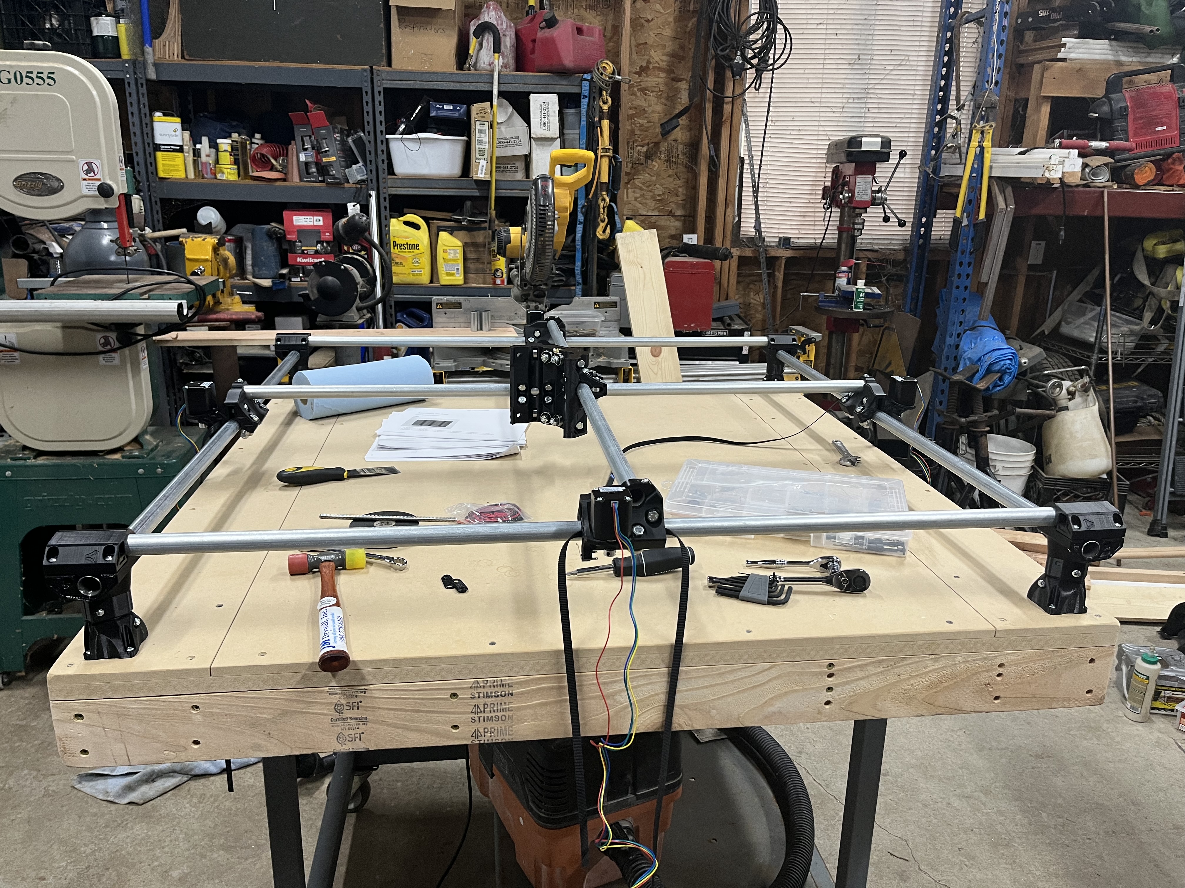
We used 2x4’s to make the frame of the table, glued and screwed them together, added a 49"x49"x3/4" MDF panel on top for rigidity, and finally screwed down a 1/2" MDF board on top for a spoil board.
Hopefully I can get it mostly, if not all done this week. I would like to get started on making some fun projects ASAP, I have a goal to hopefully eventually add a Lowrider to my collection with the MPCNC.
Finished up the gantries, and now I am working on the core.
Does anybody know if a 36"x36" working area is too big for finish work (e.g fine letter carving, sculpting, and precision aluminum part making)?
And I am looking into ways to convert pencil and paper drawings into caving patterns that my cnc can follow, I know of Vcarve-pro, but its kinda pricy. Does anyone know of a free alternative?
If you want that size then the LR3 would be a better option. My 24”x24” was too big for fine detail. I get better detail out of my full sheet LR3. That’s why I’m turning the primo into dedicated laser and building a second smaller LR3 36”x60”
Welp, ima still see what I can do with it, I would like to mess around with it a little bit, and try a few different things before I start shrinking it.
Thanks, hopefully I will be able to get good carving results with that method, its a lot cheaper than half a MPCNC a month.
I have recently shrunk my MPCNC by just sliding everything in along the rails. You could always do that. Cut the rails for 36"x36" and then assemble it smaller.
The MPCNC is very easy to resize without needing to re-cut the tubes, so I’d try it at 12" x 12" first and then work outwards. I suspect something big will be much harder to tune/debug than something smaller.
Thats a very good point, I might just try that. I am going to put a makita 700 series router on it, and I just finished everything except the Z axis, which I will start on after I am done printing the makita mounts. Hopefully my current workspace will work decent for what I need, if not I can always adjust it later like you said.
Got all the way up to the start of the Z axis today! Im excited to put the Z axis on, mount the router and start wiring this monster up! Should have it mostly, if not all done by the end of the week.
They stop or assist flex on the outside. However the pipes for the router cannot be supported so they flex. Keep you z low and that will help too. Good luck.
Thats an interesting concept. So far the outer rails have stayed pretty strong and consistent throughout trying to square this beast, it took quite some time to square it.
We removed the core twice and squared the trucks twice, clamped the trucks in place, loosened everything, retightened everything, and still couldn’t get it more square than half an inch.
We ended up removing the core from the Y axis, and squared that side by adjusting the two bolts on the trucks, finally got it within a 1/16th of an inch difference between the two trucks on the Y axis.
Once we did that we clamped the trucks in place where they were so they wouldn’t accidentally get bumped and get out of square, and added the Y side of the core back on, making sure we didn’t tighten them too much or too unevenly.
Core is done, Z axis is done, squaring is done. Tomorrow I am going to start on the belts and hopefully don’t mess up the squareness in the process
My table looks almost just like yours. I built a torsion box and worked on top of that. My height is similar (not much leg showing) and that’s the one place I may re-engineer. Like others suggested I was wary of too much z-height introducing instability so kept it low. But once you add a spoilboard, things get tight. I need more time with the machine, but I may fine myself adding a spoilboard-height of wood under each of the legs. This shouldn’t impact the accuracy of the machine because I’m not changing the geometry (or maybe it will as it’s reaching farther), but I’ll gain back 3/4". Anyhow, not enough experience to know if it’ll be an issue so not taking action just yet.
I’ll second the flex comment. Not sure what diameter rails you used. I used 3/4 conduit and i see considerable flex mid span, unless very small DOC is used. My working area is 2’x3’. I’ll be shrinking mine down to 24"x 24" overall, once my other machine is complete.