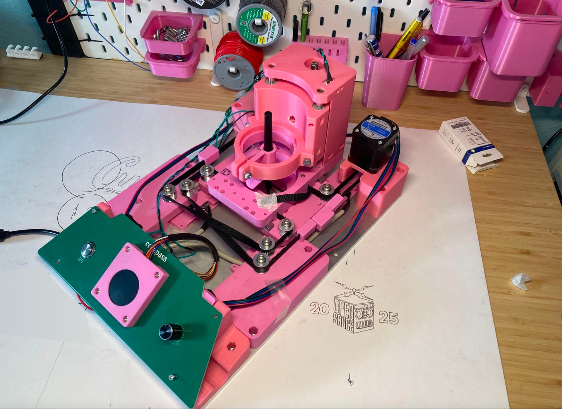
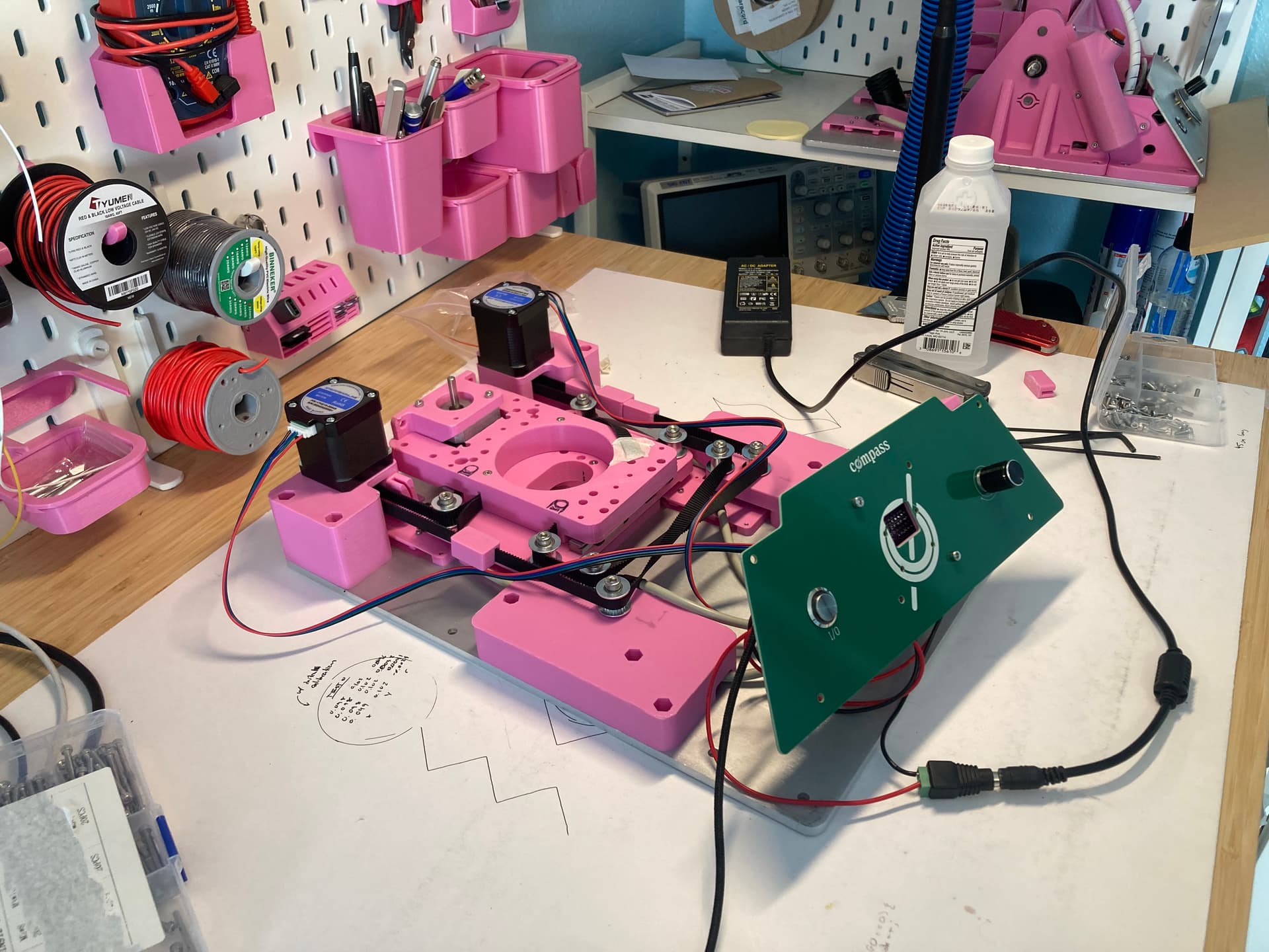
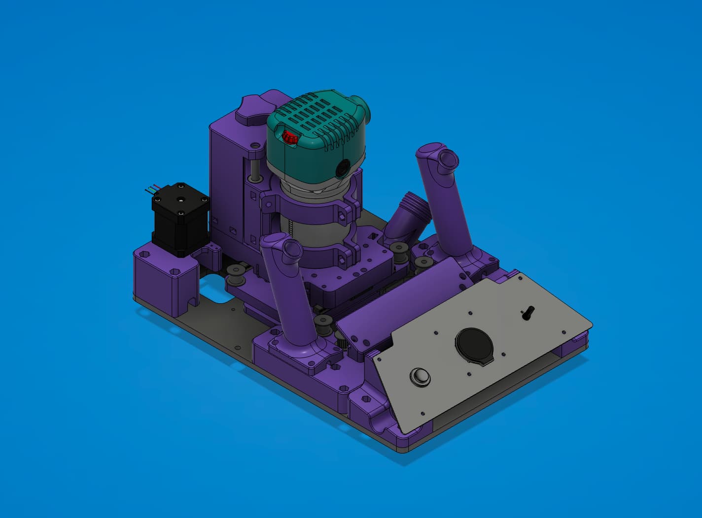
Heyyo guys, been a minute since I’ve shared a tech update, but trust that things have indeed been happening. I’m stoked to finally share the fruits of my labor: the new 3 axis handheld CNC router design! I’ve been wanting to implement a 3 axis motion system for quite a while now, but have only just recently settled on a satisfying way to do it effectively (thanks Ryan for helping brainstorm and throw ideas at the wall). I whipped up a proof of concept last week and it’s working! It’s still definitely not perfect, but even just from initial testing it is proving to be leagues above the previous 2 axis version.
The main advantage of adding another axis is that it dramatically improves the device’s path tracking abilities. It can now correct forwards and backwards as well as just left to right, making more complex designs a lottt easier for the user. There is no need for rotating or repositioning the device, as was necessary before.
This also means that the CAD → CAM → runtime workflow is a lot simpler and smoother. You can pretty much just treat it like a standard CNC machine when planning setup and operations. Contours, drills, pockets, etc. are all fine. This vastly opens up possibilities for more precise and intricate projects.
I’ve also whipped up a much more intuitive user interface, improved spindle mounting, and better cable management, among other little improvements.
I’m going to be posting some videos of testing soon, but the main priority right now is making everything more robust for RMRRF. In the meantime, if you have any questions or thoughts, I’d love to hear em!
Nice! Like the same plane cross over corexy belt routing, similar to MP3DP v5 but with steppers relocated to reduce overall Idler count (and motion resistance/vibrations?). Does wider spread/spacing (along Y axis) of Core Idlers (compared to MP3DP v5) help resist twist/racking forces? Wonder if coplaner Idlers potentially enables chassis/parts to be milled instead of printed… Looks great!
Nice wide belts, easily capable of moving larger motion range… The larger the usable CoreXY based X and Y range, the less the User will need to precisely move the assembly for a given job. I.e. easier User experience for more usage scenarios… So, I wonder what the sweet spot for project sizes is (hopefully you can capture opt-in or opt-out summarized IP/PII scrubbed metrics from beta customers to understand usage patterns). Am wondering if most, or many, or enough people even… Are most people mostly making Coaster (100mm x 100mm) or smaller sized projects? Larger Usable XY means larger overall assembly, maybe something interesting can be done here to minimize footprint… For Open Sauce 2024 we fastened Maslow belts using modified clamps at the corners…
Full disclosure: Am 40,000ft above Canada somewhere enjoying free adult beverages, apologies for silly ideas/distractions. Love how Compass is evolving and progressing!
Yup! The main goal was to reduce idler count and simplify the design. With same plane routing I can just mirror most of the parts and keep things a bit more compact. I’m not sure what the effects are on motion resistance/vibrations.
That was my intuition hahah… Tbh I’ve never designed a belt system before, so I don’t have a lot to go off of. Love hearing any feedback!
In terms of the motion range, totally like you said there’s definitely a balance. The bigger you make the range, the bigger and more clunky the device becomes. For the 2 axis version, I originally wanted to make the range as big as possible (while still having a hand tool comparable form factor) to improve the user experience. Because the user had to control the device’s orientation as well as well as just position, the big range made it easier to stay in bounds. Now that the user only has to control position, the working range can be a lot smaller. I’ve gotten a lot of feedback that the 2 axis version’s range was already excessive, so I made this one quite a bit smaller. It’s now 20x20mm, whereas the previous version was 100mm (I think shaper is 12x12mm). I guess we’ll see if that needs to be modified…
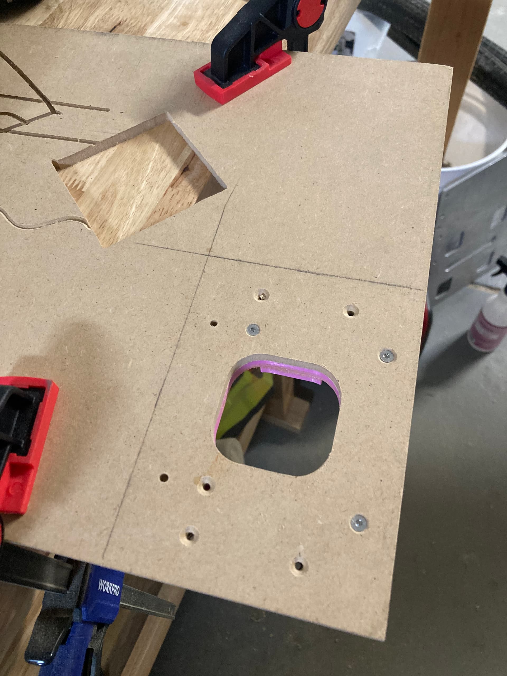
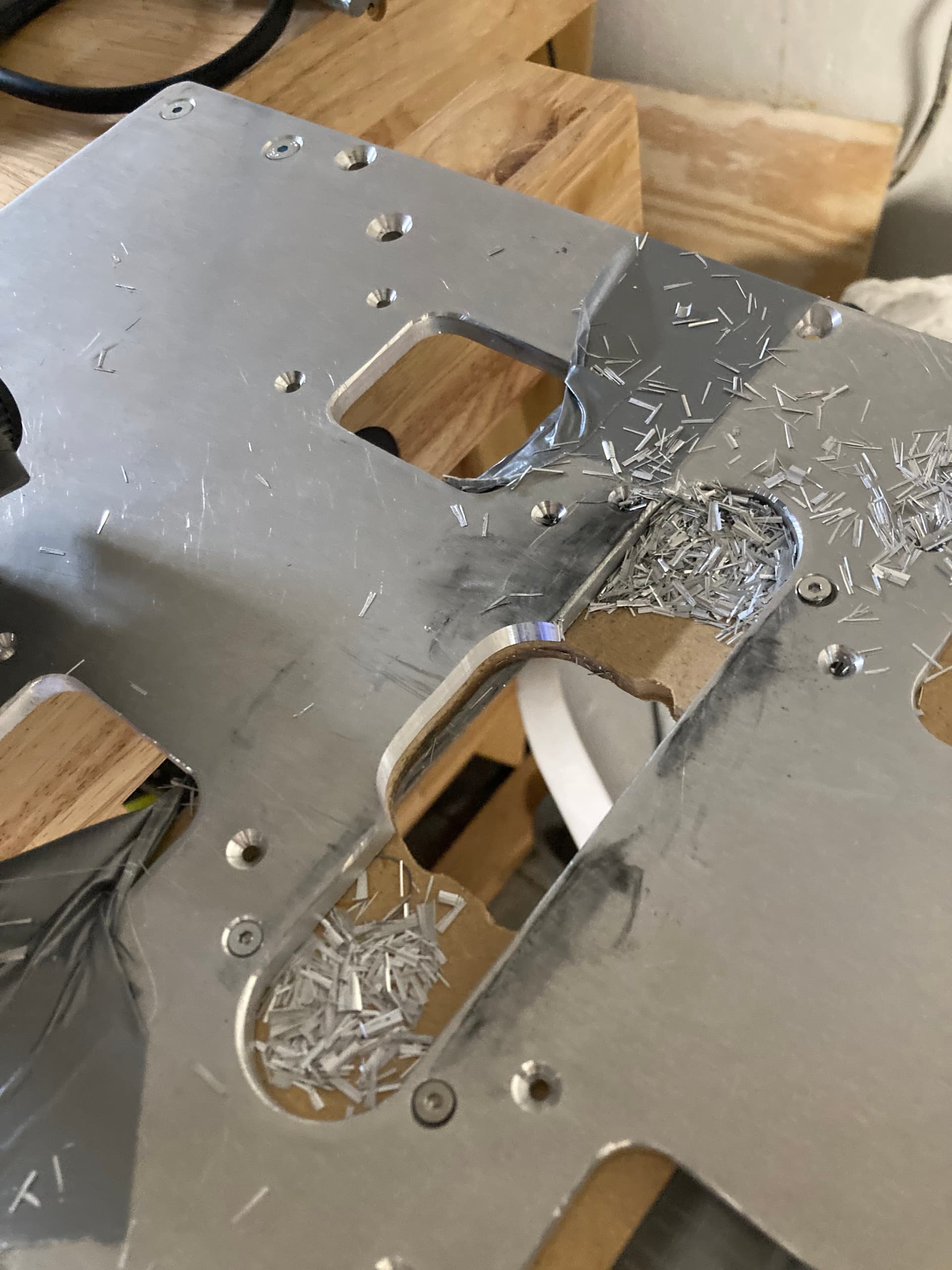
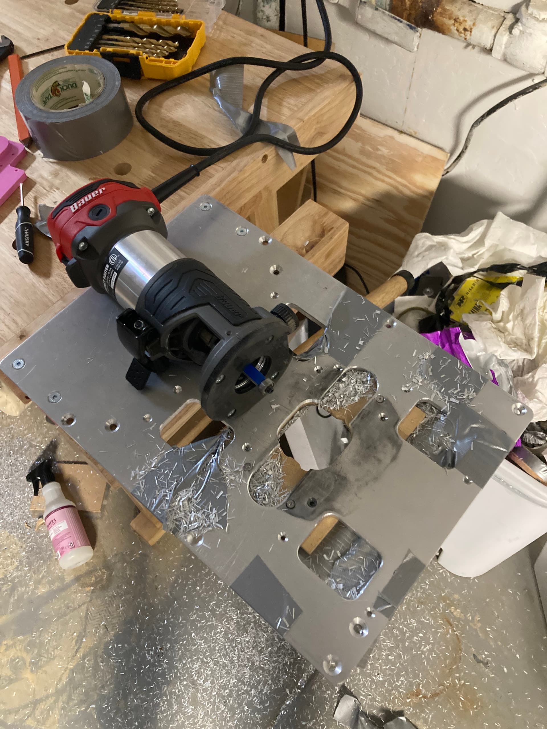
@jono035 finally got around to using your aluminum trim router method, and it worked pretty good! I needed to widen the tool slot for the 3D version so that the collet nut wouldn’t run into the baseplate in the y-direction.
Might be a little roundabout haha but it did the trick. It didn’t need to be accurate, just provide enough clearance for the router. I definitely could’ve used a better bit but I wanted to see if it would work with a standard flush cut bit (because I’m cheap and Amazon had a set of 8 for 20 bucks). Short answer is sort of, but I had to take pretty shallow passes and keep a really steady hand to not get terrible results. I also may have broken my 3/8" bit earlier on in experimentation…
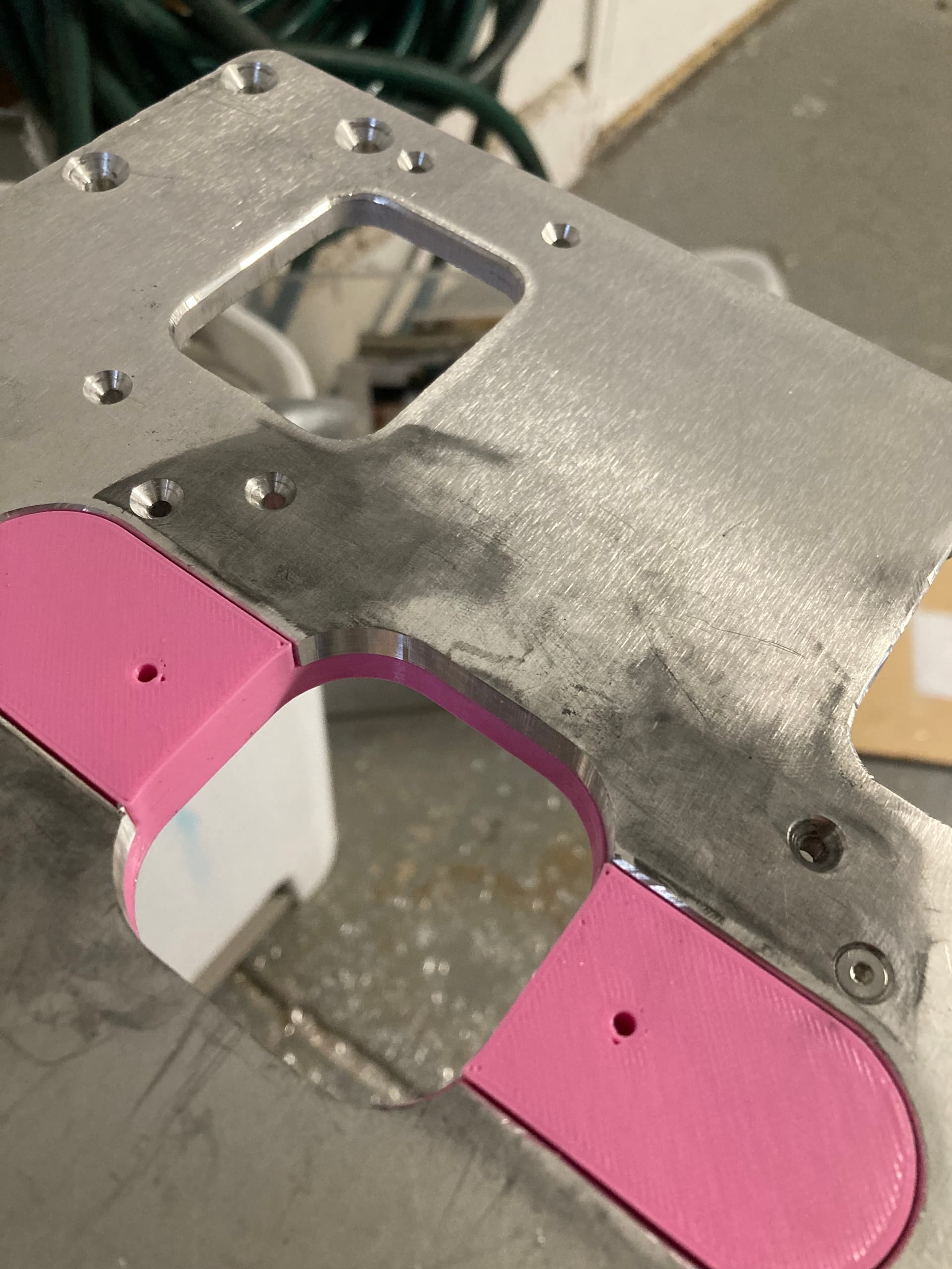
I then popped the 3D printed jig back in to clean up the edges because it seemed like my duct taped MDF jig holding might not have been exceptionally precise.
All in all, a fun experience and it got the job done. Cool to see how far my trim router will go trudging through aluminum. Now onto some cutting with the new handheld cnc router!
Awesome result! I really like the idea of using the 3D printer to bootstrap an MDF pattern.
I’ve only tried it with a spiral bit but I was able to take surprisingly heavy cuts. Definitely still to the point where it’d be best used for starting from a jig-sawed hole and making it cleaner/more accurate, though.
I’ve never tried it in aluminum - but I’ve use that method of 3D printing patterns to use with a router a couple of times on things that were either too big for my MPCNC or when I just didn’t want to bother moving all the stuff that had collected on top of it off.
I will warn though - make sure you’ve got the depth of your bit set very carefully. I had a few close calls when my flush trim bit just barely hit the 3D printed pattern and the whole pattern just disintegrated like a prince ruperts drop
Love the idea of going from 3D printed pattern to MDF pattern to cutting aluminum though!
Yeah, that’s definitely a consideration. I prefer the approach of using a pattern bushing rather than a following bit with a bearing. That also helps by making it a lot harder to nuke your pattern, in my experience.
The bushing approach has the advantage of being a fixed height relative to the base rather than the bit so you can use it for shallow trenches/dados or making a deep cut in a bunch of steps. The main downside is that the bushing is always bigger than the bit so you need to have a pattern that reflects that.
If you’re doing stuff in CAD then the change in dimension is a lot easier to manage. It’s relatively easy to dimension structures as the size you want + the bushing clearance or to draw the structure you want and then use an offset tool to expand it.
It can also be a little bit of work to get the bushing lined up exactly with the bit but for most stuff I’ve done it doesn’t matter if there’s a small ~0.5mm offset. I just make sure to either not rotate the router as I’m moving it if I want the pocket size/shape to be accurate or keeping the router aligned with the path I’m following, depending on the goal. There are methods for getting it aligned but I found them a bit too finnicky with the bases on palm routers. In the end I made myself a large acrylic base and cut a step in it for a pattern bushing that I could accurately align and leave in place. I use the spare base from the router in my MPCNC to do all my general purpose stuff and keep that base as purely a pattern follower base.
Yeah I can imagine that working quite a bit better. I had to go extremely shallow to avoid biting and getting bucked.
Ahhh yes, I had some experience with this too. You might notice the MDF jig is a bit chewed up in some spots. Luckily I made that mistake on the test piece of aluminum.