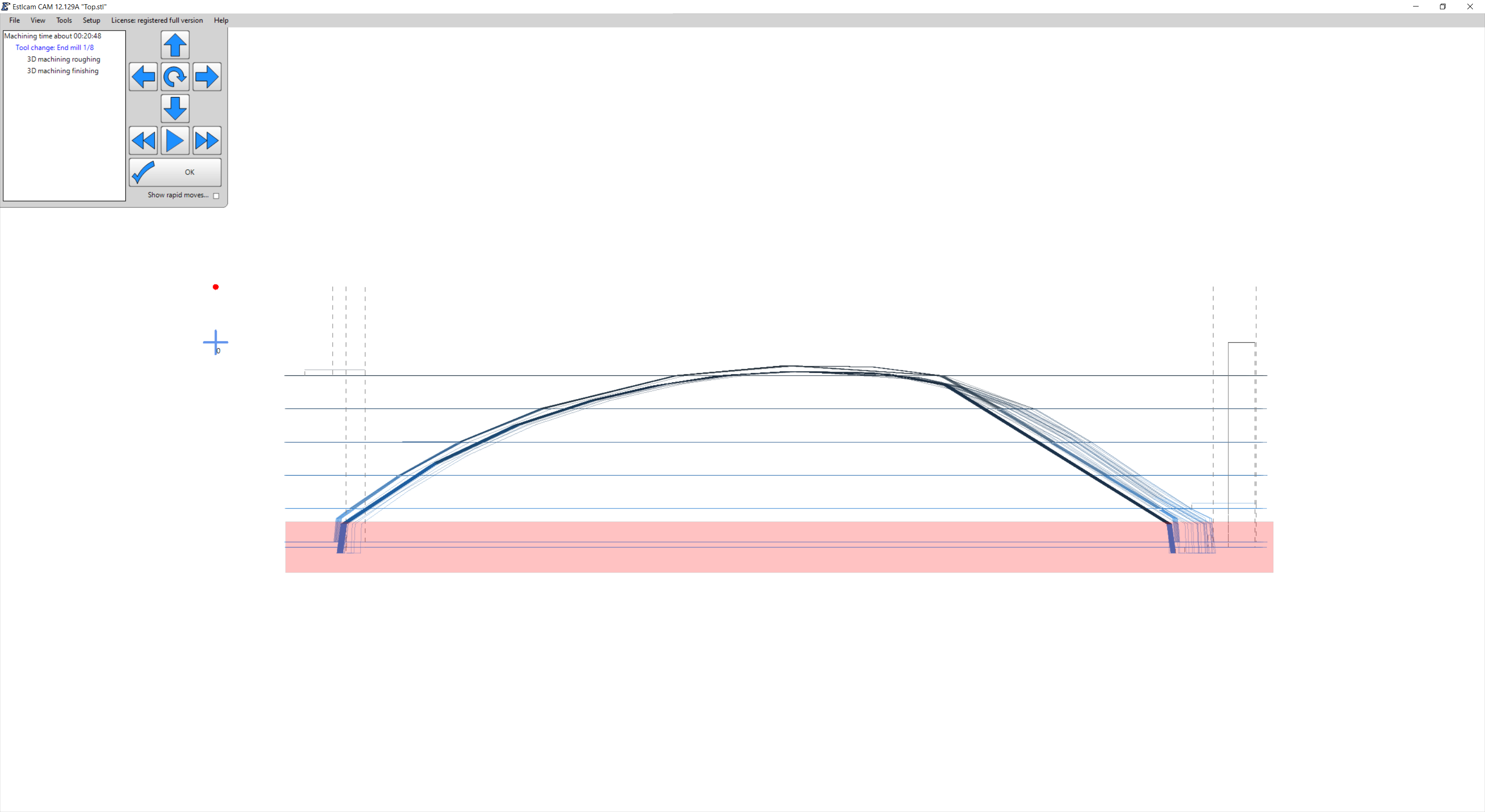
OK, I don’t understand something. I’m trying to cut out a really simple model that is flat on the bottom. It’s 15mm tall and I have a 3/4" piece of wood, so I would think it would clear out 4 mm first and then start with the model if I put a material height of 19mm. But that’s not what is happening. Instead, it places the model halfway into the wood like it is trying to do two sided machining even though that box is unchecked. Am I doing something wrong?
Not even sure what to search for to explain so I hope the image helps.
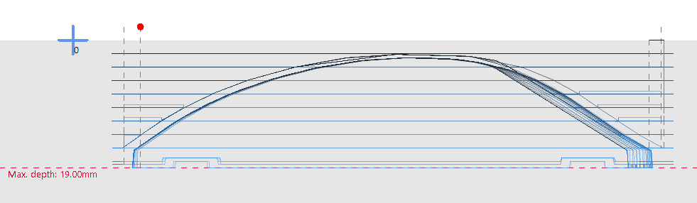
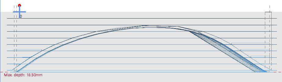
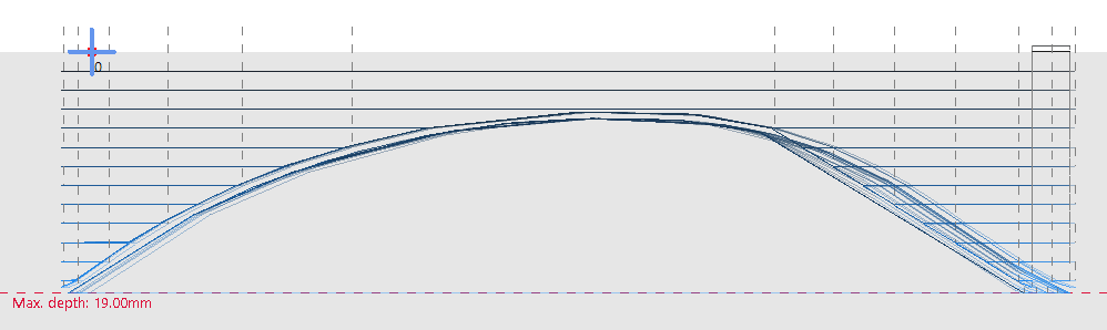
Something is wrong with that image. If you double click the preview until you get to the side view it will show a Max depth:. Example is 14 tall in 19mm material. I assume you’re using Block because you want tabs, the Free equivalent is material - STL = Shift downwards setting.
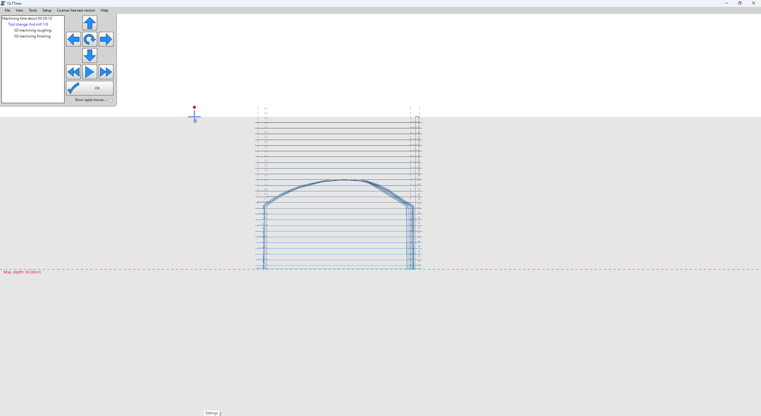
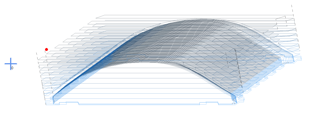
In V12 it does, so here are some screenshots in V12. No matter what height I set the workpiece to, it places it in the middle. Exaggerated, here’s a 80mm workpiece height. Two sided machining is unchecked.
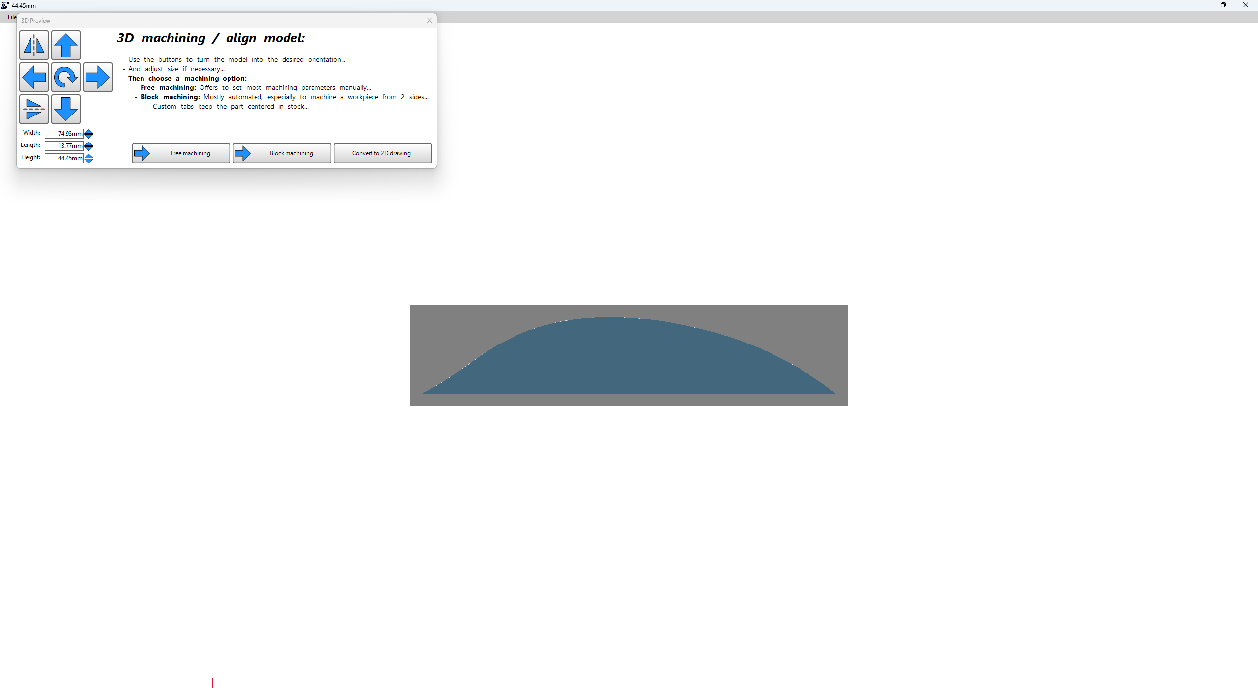
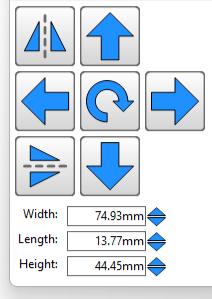
You need to rotate the STL so that the top side is up and your Height is 13.77mm. Those Width, Length and Height numbers correspond the the absolute minimum material dimensions.
…You have your material thickness set to 80mm and the bottom of the 74.93 Width x 44.45 Height face of your STL is also at 80 (Max depth), i.e. nothing wrong there.
I’m clearly not explaining myself correctly. The last pictures were just to show an exaggeration
of the issue and what the side profile is meant to look like. That’s not how I had the model when I generated the gcode.
Maybe it’s just best to share the STL and someone might show me why I’m not smart enough. TopSolid.zip (27.2 KB)
That model isn’t at the bottom of the workpiece. So the piece that it cutout is taller than the model itself by about 2 mm. If you were to try and cut it out of a thicker piece of wood, you would end up with a different piece that was thicker yet.
My bad, I totally missed that your first image was highlighting added vertical sidewalls and that your second shows how the sidewalls grow with increased material thickness… The same thing happens with the STL used for my earlier image. Like you said, it appears Estlcam is centering the original model and extending the sides down to the bottom of the material… While bizarre and unexpected it doesn’t appear to be a new issue (12.036 from '23 does the same thing).
Free machining is fine and works if you can live with leaving a bit of material in place of tabs (.5 in the example).
I guess it makes sense for 2 sided machining, but I would expect 1-sided machining to work different. This particular part isn’t a huge deal, but I have others further in this project that will cause some headaches leaving much more material.
I guess I could just run a simple job to cut down the wood to the necessary height first, and then do the carve. A tedious process but it could work. I’ll email Christian and see what his thoughts are.
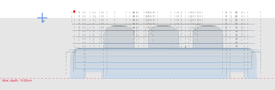
While I’ve used a tabbed 2D perimeter path to cut that last bit using a 3D > 2D mask file, it wouldn’t be ideal for that pointy wedge on the right side. An alternative is to cut the flat/vertical/straight front and back faces in 2D (w/ tabs). Example is Free machining w/ Shift downwards: 5.23 and Margin 2.3.
In this case (your STL w/ a 1/8" tool) the maximum Margin is 2.3mm which is enough to fully cut the right and left faces. I’m not sure how much smaller the margin could be, but any bigger and there is an oddball single full depth finishing pass on the front and back faces, i.e. use the isometric view to insure that there are zero passes on the front/back faces.