The most tedious, but hands-on approach would be to find the exact dimensions on each of the sides - draw them in inkscape, add necessary details for tenons and joints and import to estlcam to set up proper tool paths.
I’ve tried to figure out the Guffy PP for F360, but it’s honestly quite overwhelming to get into the whole workflow using F360+Guffy and the Manufacture flow. Are the ways to make such an object in F360, and have Fusion automatically create each of the sides/plates in an efficient way?
This specific box wouldn’t take a long time to draw as 2d in inkscape. But I think that in the long run I would benefit from figuring out how to use F360 all the way, to be more efficient. But how much more efficient would a good F360 workflow actually be??
I am not qualified to answer, having only learned to draw in CAD since November. After the F360 kerfuffle I began playing with OnShape and while I’m no expert, surprisingly I can find my way round it well enough to draw things with ease well beyond my expectations. (Note I have had a lifetime of drawing by hand in traditional 2D formats, so would have no problems at all developing your box the “long” way.)
In this instance I think 3d cad would be able to automate your joint construction a lot faster with a lot less margin for error and make it easy for you to explore detail options that would take some time by hand. See HERE as an example of what I’m talking about.
Don’t ask me about exporting to CAM, I’m not up to that chapter yet!
By the sounds of it you will be constructing this from Flat parts. If so the best would be to draw it as such and put all the details for the tenons and joints right into the part. The post processor for Fusion works well. I’ve used both Guffy’s and my own which I did simply for Grbl.
Is this an existing model? If it is it could be imported into Fusion.
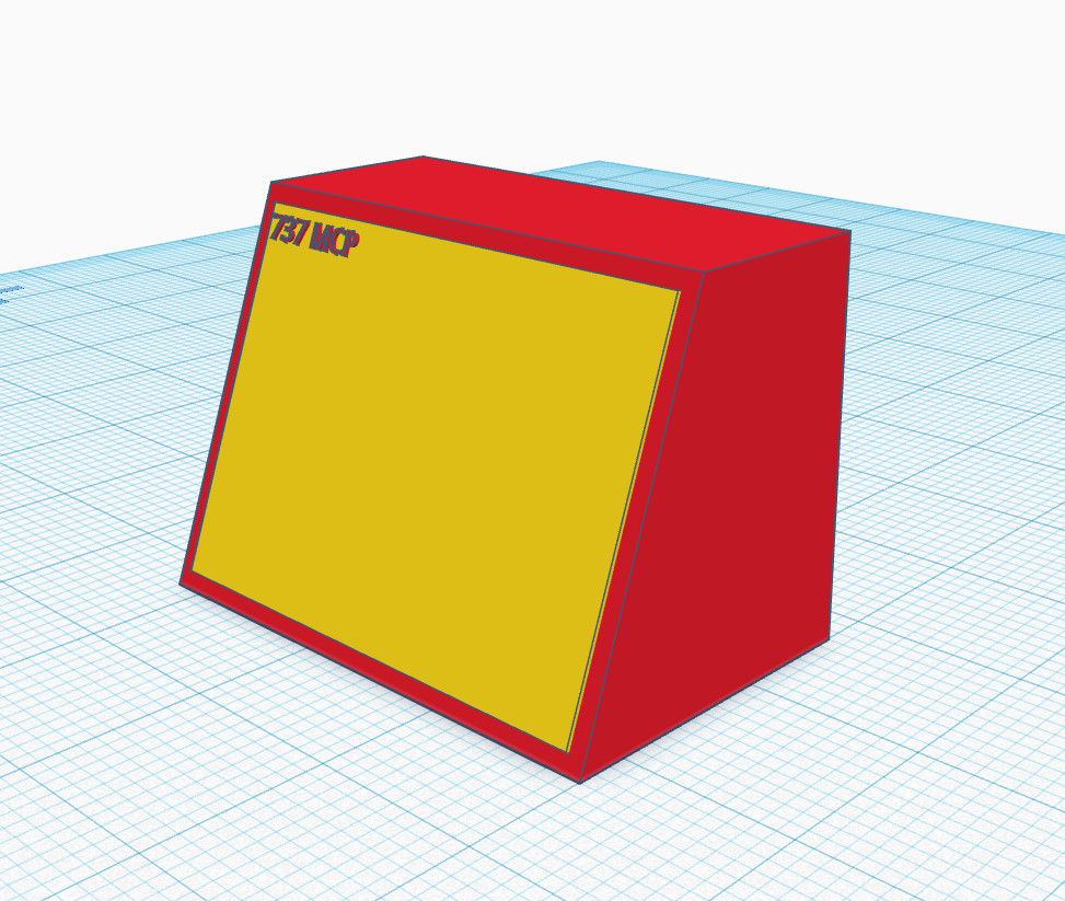
You have an angled cut on the top, which means you’ll need to do some post processing (like cutting that on a table saw, or a ton of sanding or planing). Same with the bottom.
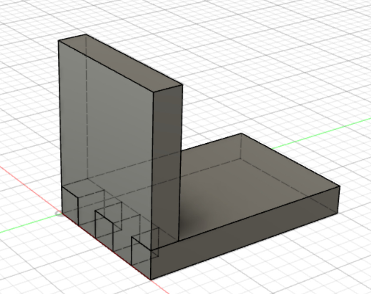
But if you wanted to make box joints (or just long tabs) to make the sides and to meet, here is what I would do (in onshape):
split the red part into separate pieces. You can cut by a particular plane and select the inside of the top and bottom to cut those from the sides.
make a sketch on the sides and draw and define the tabs that go up into the top and bottom
extrude those to add them to the sides. They will interfere with the top and bottom at this point
do a boolean operation (subtract) to remove the tabbed area from the top and bottom. You can choose params for an offset here if you want to leave a small gap.
At this point, you will have the object separated and designed with the joints. You could open up kiri:moto and cam there, or you could make a new sketch on each part, trace the features, and export as dxf. Then import the dxf into estlcam. If you use kiri, you will need to draw dogbones, or trim out the corners with a chisel. Estlcam can overcut the inside corners.
If you’re going to leave the top and bottom long to cut that angle, make sure you trace the long face, not the short.
If you wanted to cut the angle on the cnc, I think kiri would be easier. But you could also try exporting the stl to estlcam.
From my experience there are few ways to avoid the details of corner joints, etc. That is one of the reasons 3D printing is so attractive. That box is not a lot different then the mpcnc case I designed using onShape. 3D printing lets you avoid thinking about a lot of those problems - except how to print without supports.
In the flat woodworking CAD I’ve done I’ve always needed to design the sub-components and then do assemblies to put them together.
@jeffeb3 is right about using the 3D intersection and subtraction features available in tools like onShape. You can design one side (with tabs or some other joint) and then reference that part in the construction of the other sides. You don’t need to draw all the details of the other sides as you use the first as the template to cut away the pieces not needed.
Getting from the model to milled material though is in my opinion harder then creating the model. The CAM tools seem less powerful (at least the ones available to hobbyists) and harder to use. I think a lot of that though comes with controlling fast spinning tools that create all sorts of forces when they hit hard things .
Thanks all for your replies, I appreciate it! I realize that I wasn’t super precise in my description, my plan is to make a hollow box. I would therefore have to isolate each side and cut them out from a suitable sheet material.
Tonight we had friends over, and one of them is actually an engineer in technical drawing. He works in Solidworks, so he couldnt help me with Fusion. But - he recommended that I made the box precisely as it’s supposed to be with the correct thickness of the walls. This way I could make the tabs myself, as @jeffeb3 mentions. Then I could isolate each side as a DXF drawing, so that the precise dimensions are kept. Then I can export and use estlcam (not because it’s best, but that’s what I’m used to an familiar with) and make the gcode. It might also be worth looking into the joint tool from @bitingmidge, to simplify the joint-making.
Well - what do you know, another day, and another bunch of stuff learned!! I guess I should get the Guffy post processor under my skin at some point, but for now I’ll stick to making the model in Fusion, and exporting each side for CAMming in estlcam.
EDIT: I realize that finding short cuts or tools to quickly solve simple tasks take more time than doing them manually. A boolean cut is quick and efficient!
Ayayay… WOW… this - is - fantastic! Thank you so much mate!
Now I’ve found my preferred workflow. Model in Fusion, make the joints and every details with a good precision, and then export SVG to estlcam. I guess the manufacture → guffy PP could be a good option, but since I’m familiar with estlcam, this would be super useful. I could even combine the SVGs using inkscape, to make larger sheets and cut several pieces at the same time.

 .
.