The documentation for the board says it only supports 12V (for now). It says there’s a future version that will support a wider range.
Ah. So it is the board with the limit. Can you try driving it at 12V? It might still work, but you may lose some top speed.
Have you tried your nema11’s on 12V?..It is not exactly a huge load it has to lift.
1 Like
This is my plan. Speed doesn’t matter much as the Z axis only moves when setting height and maybe once or twice while trying to cut through thicker material.
I will hopefully be able to test next week.
1 Like
Yeah. So… About this thread…
Now that my recent printer upgrades are mostly complete, I think it’s finally time to work on this again.
This afternoon I’m going to dig around the shop and try to find the parts I bought for this.
3 Likes
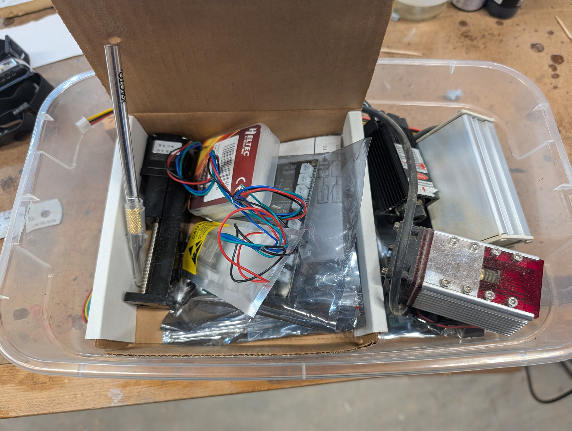
I has a .357 inch of dust and dogs hair on stored items.
The dog hair is all over the house. The dust is why I started storing all projects in these clear plastic tubs. At some point I was even smart enough to label some of them. This project box was not during that ‘smart’ time frame.
I’ve made good progress on the upgrades today.
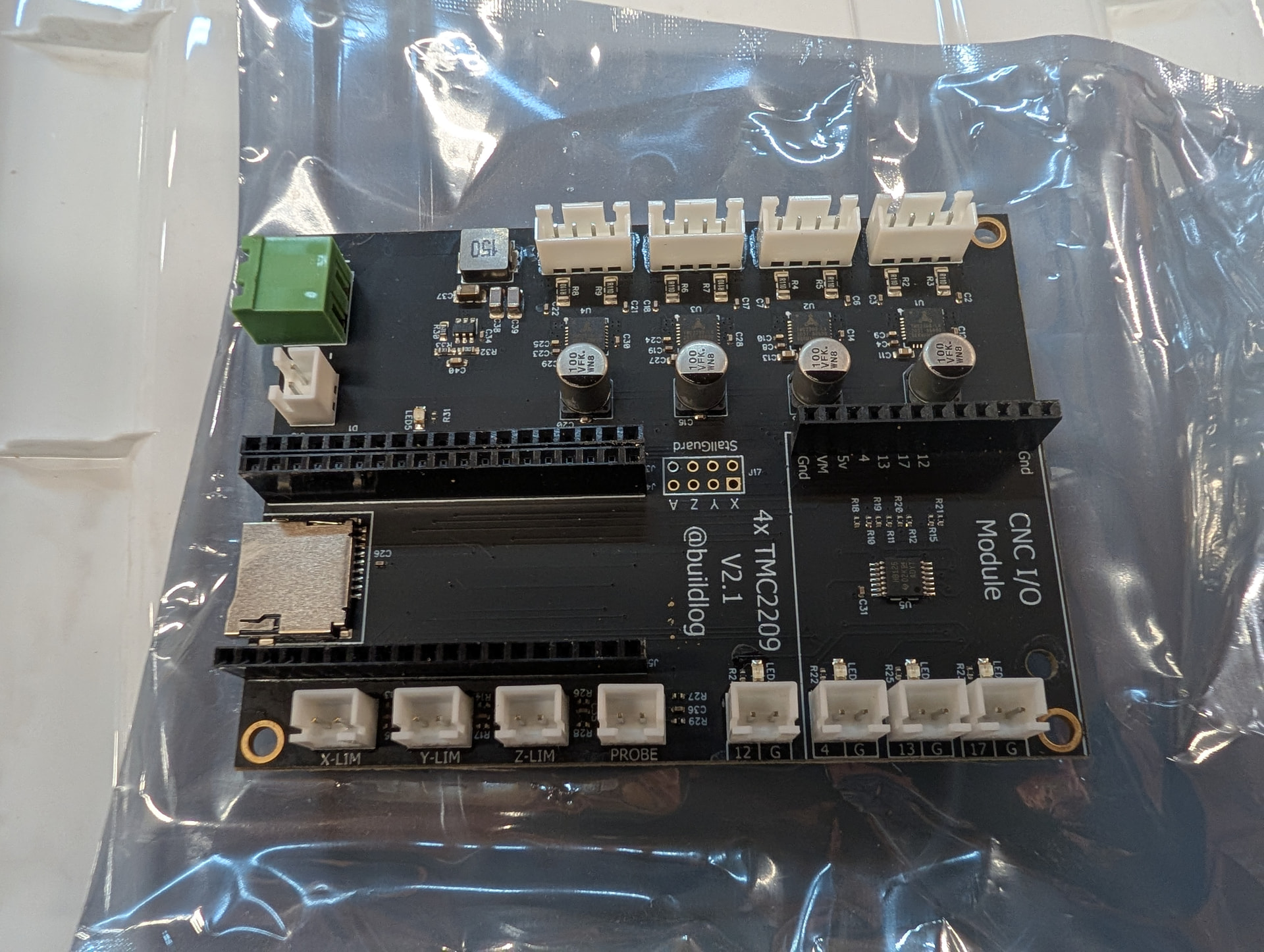
Step 1) Get the Bart Dring board flashed and ‘working’ with FluidNC
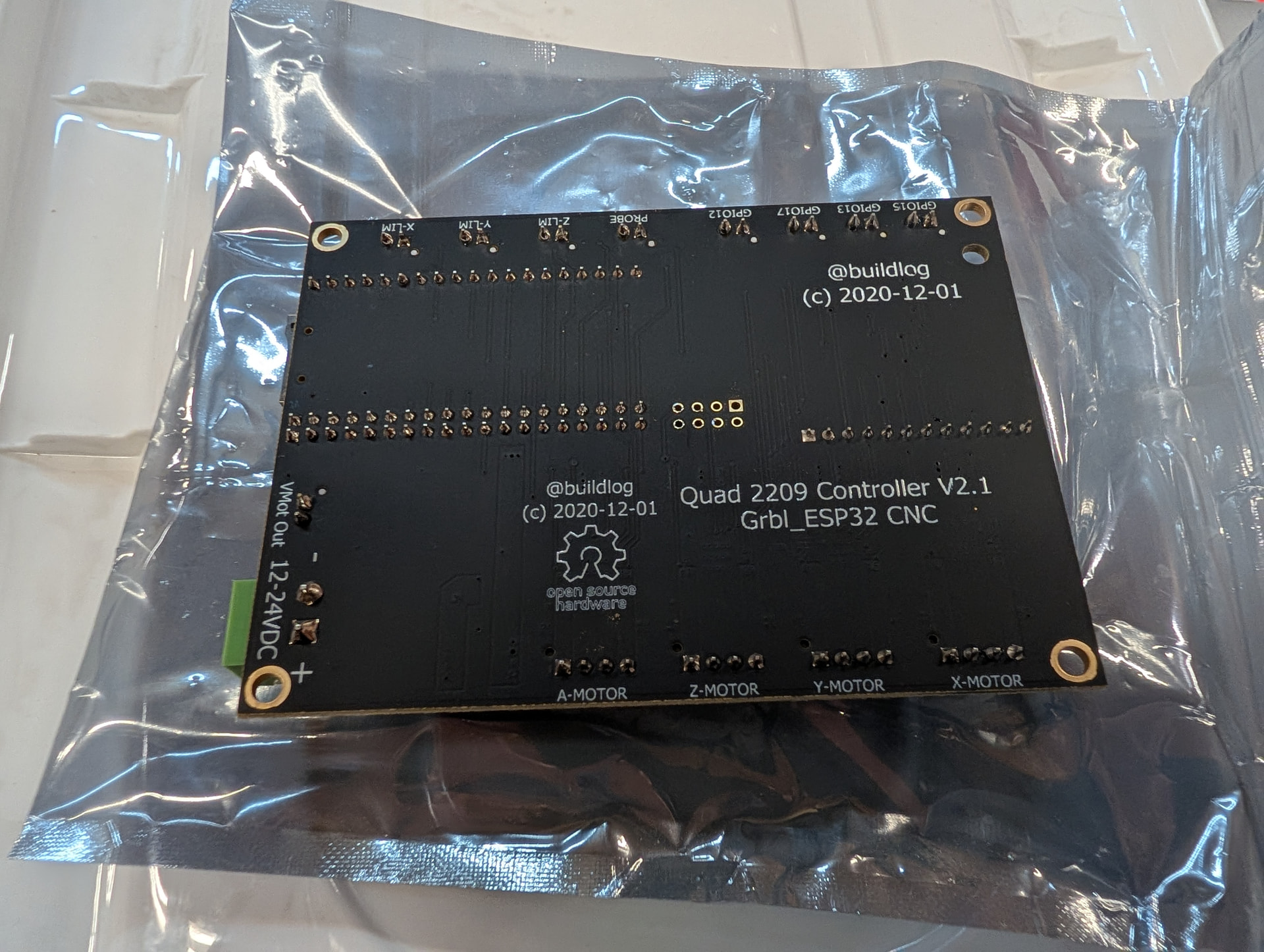
I got the board flashed and hooked a stepper motor up to it. The board I’m using is an older one that doesn’t show up in ANY of the FluidNC documentation.
My board is this one: GitHub - bdring/TMC2209_4x_DK: TMC2209 4 Acis Grbl_ESP32 Controller My pinouts seem to align with the V2 versions of this board.
Here’s the working config.yaml that I managed to at least get the X-stepper motor turning with. I need to set it up for dual Y-steppers and at some point I need to try hooking up a laser.
I tried to get Gemini to help write the NC code. It kept insisting on using newer versions of the board even when I pointed it to the github link and told it to use V2. It’s a good thing I can read schematics. It also kept trying to use the I2S that the newer boards are using.
name: TMC2209 4 Axis V1.1
board: FluidNC 4X 2209
stepping:
  engine: RMT
  idle_ms: 250
  dir_delay_us: 1
  pulse_us: 2
  disable_delay_us: 0
uart1:
  txd_pin: gpio.22
  rxd_pin: gpio.21
  baud: 115200
  mode: 8N1
  rts_pin: NO_PIN
axes:
  shared_stepper_disable_pin: gpio.25
  x:
    steps_per_mm: 400
    max_rate_mm_per_min: 5000
    acceleration_mm_per_sec2: 150
    max_travel_mm: 750
    motor0:
      tmc_2209:
        uart_num: 1
        step_pin: gpio.26
        direction_pin: gpio.27
        addr: 0
        r_sense_ohms: 0.11
        run_amps: 1
        hold_amps: 0.5
        microsteps: 16
      limit_neg_pin: NO_PIN
      limit_pos_pin: NO_PIN
      limit_all_pin: NO_PIN
  y:
    steps_per_mm: 53.33
    max_rate_mm_per_min: 18000
    acceleration_mm_per_sec2: 950
    max_travel_mm: 410
    motor0:
      tmc_2209:
        uart_num: 1
        addr: 1
        r_sense_ohms: 0.11
        run_amps: 1
        hold_amps: 0.5
        microsteps: 16
        step_pin: gpio.33
        direction_pin: gpio.32
      limit_neg_pin: NO_PIN
      limit_pos_pin: NO_PIN
      limit_all_pin: NO_PIN
  z:
    steps_per_mm: 400
    max_rate_mm_per_min: 200
    acceleration_mm_per_sec2: 25
    max_travel_mm: 200
    motor0:
      tmc_2209:
        uart_num: 1
        addr: 2
        r_sense_ohms: 0.11
        run_amps: 1
        hold_amps: 0.5
        microsteps: 16
        step_pin: gpio.02
        direction_pin: gpio.14
      limit_neg_pin: NO_PIN
      limit_pos_pin: NO_PIN
      limit_all_pin: NO_PIN
  a:
    steps_per_mm: 400
    max_rate_mm_per_min: 200
    acceleration_mm_per_sec2: 25
    max_travel_mm: 200
    motor0:
      tmc_2209:
        uart_num: 1
        addr: 3
        r_sense_ohms: 0.11
        run_amps: 1
        hold_amps: 0.5
        microsteps: 16
        step_pin: gpio.16
        direction_pin: gpio.15
      limit_neg_pin: NO_PIN
      limit_pos_pin: NO_PIN
      limit_all_pin: NO_PIN
4 Likes
Got it burning again. Took some trial and effort to get the ttl set right.
Now to print a mount for the controller and work on getting the Z mounted.
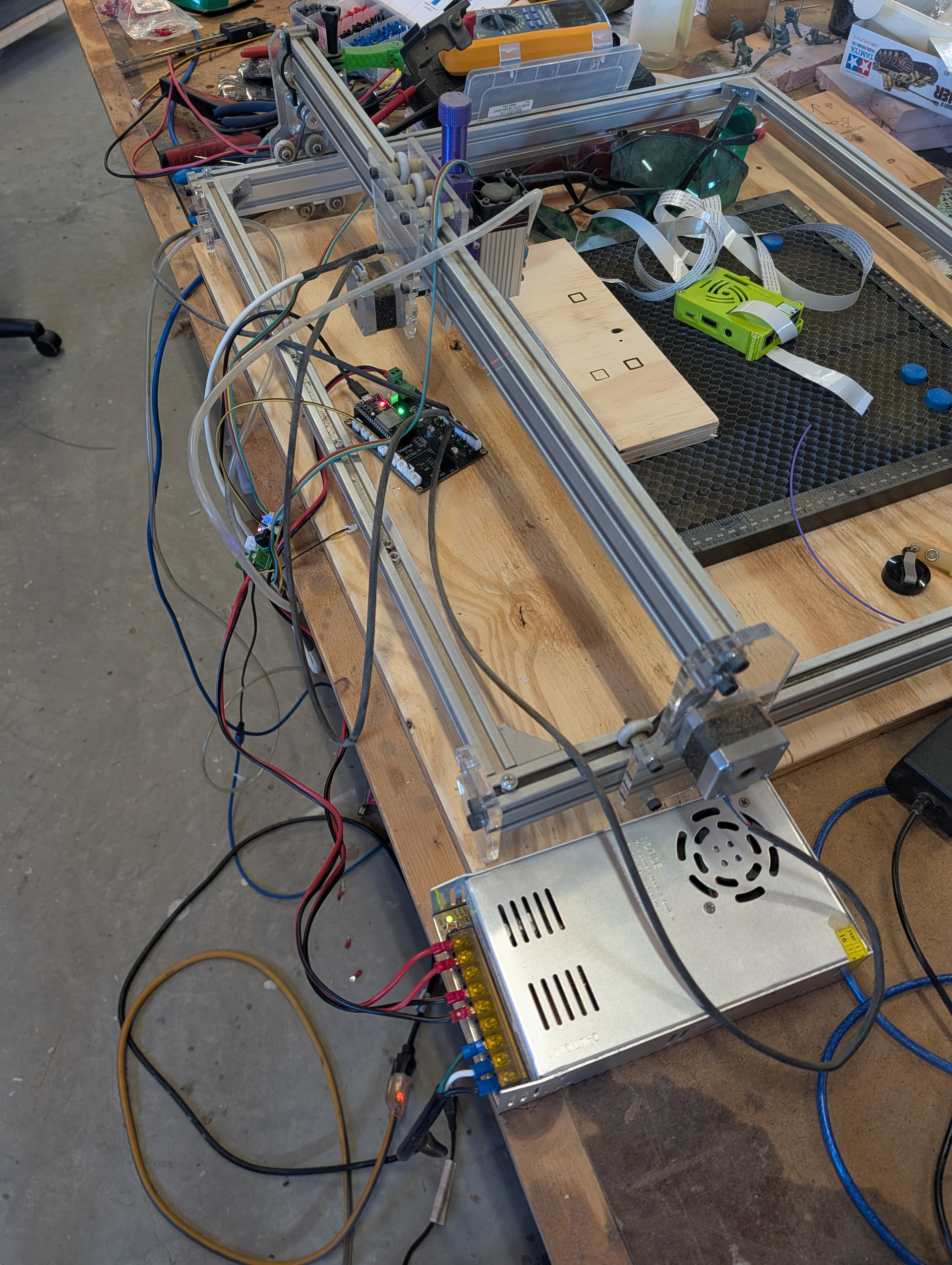
5 Likes
Got the Z moving and calibrated. Need to design a mount now.
3 Likes
I had today off. I got a lot of work done on this machine.
I have the Z mounts pretty much finished, just need to print the last version.
The solenoid for the Air Assist came in, so I need to design a mount for that. I’m having to order some more 5v relays, so I’ll design that mount when the relays come in. Then I need to extend the stepper motor wire for the Z axis and it should all be done.
Pictures to come once everything is complete. The MP3DPv4 has been a champ pushing out prototype mounts one after the other today.
1 Like
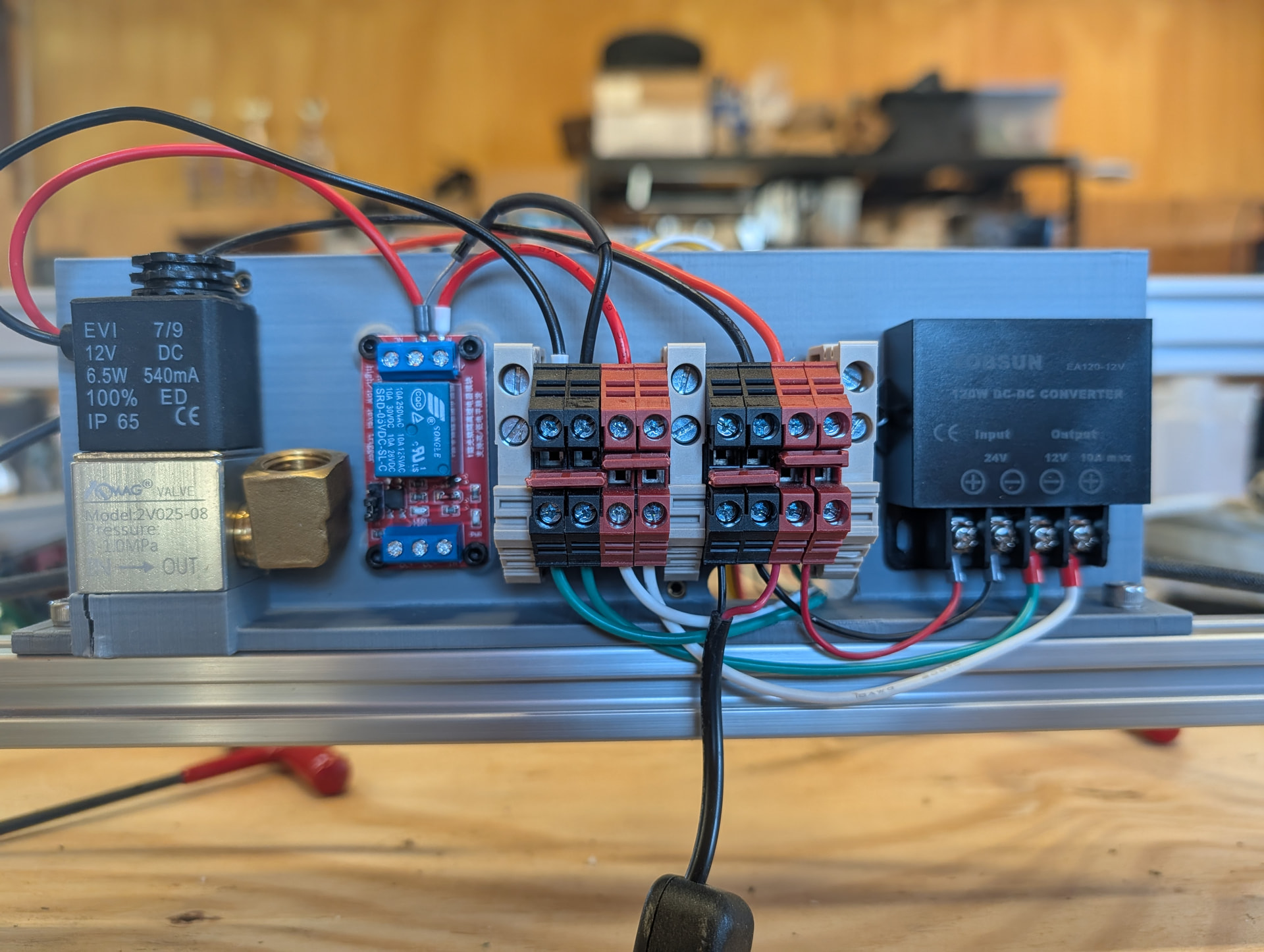
Ok. I have all the electronics sorted out. I’m switching the system over to a 24v PS for the steppers and BartDring board. I have a 24v->12v buck converter that will handle the 12v laser and solenoid. I’m using spare parts from the MP3DPv4 build for some of the electronics. I am having to use a 5v relay to trigger the 12v solenoid. The BartDring board does have a 12v output that says it’s for low-voltage lasers. I could probably figure out how to trigger that for the solenoid, but I’m afraid of the solenoid frying the controller. As it sits, I’m already planning on wiring in a flyback diode on it.
Here’s some renderings of the mount plate I’ll be printing. This will mount on the back rail of the laser. The controller will be on the gantry side and the solenoid and power stuff will be on the backside facing the wall.
The PS is a 24v brick, so no bare 120vAC stuff I have to worry about protecting. I’ll probably design a lid for the electronics box at some point.
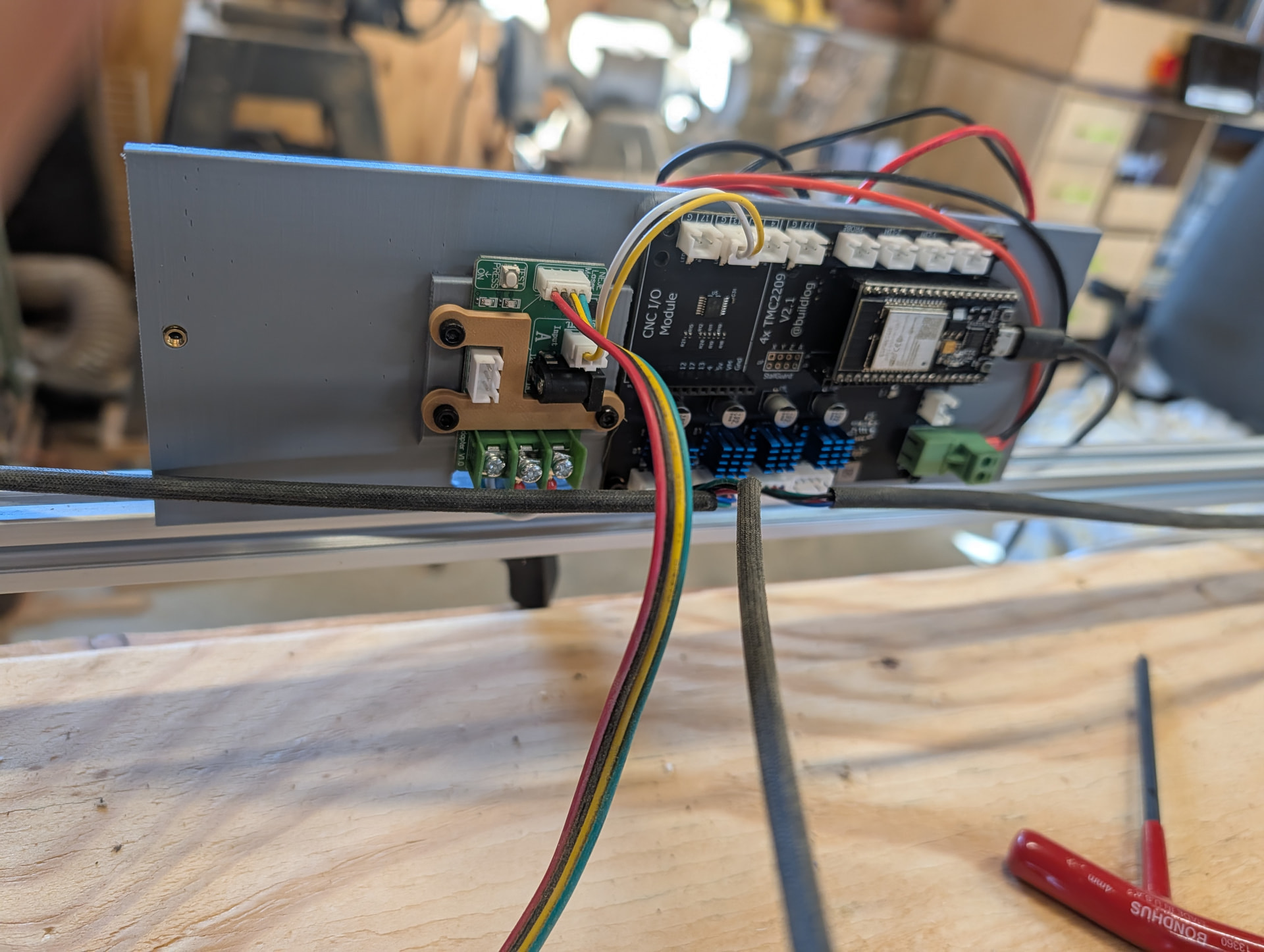
The laser controller doesn’t have mounting holes, so I printed this little plastic clamp that fits around the connectors to hold it down. I’ve tested it out and it works quite well.
Controller side (no, I didn’t completely build out the board’s components in FreeCAD)
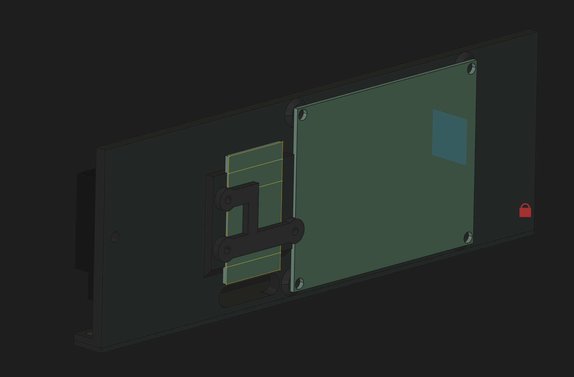
And Power/Solenoid side. The green rectangle is the relay board, the silver rectangle is where the 24v/12v Terminal Blocks will be mounted. The black box is the 24v12v converter. And the grey rectangle is a bad representation of the solenoid.

This is a 5 hour print, so it will have to wait until Sunday at the earliest. I have stuff going on the next 2 days, so no rush.
2 Likes
Got the new mount printed. Ignore the cracked plastic. I thought I needed M3 bolts for the solenoid and it’s M4. I’m sure I’ll reprint it one day.
I still need to lengthen the Z stepper wire and wire up the solenoid. The I’ll try to add on the biqu microprobe for setting the Z height.
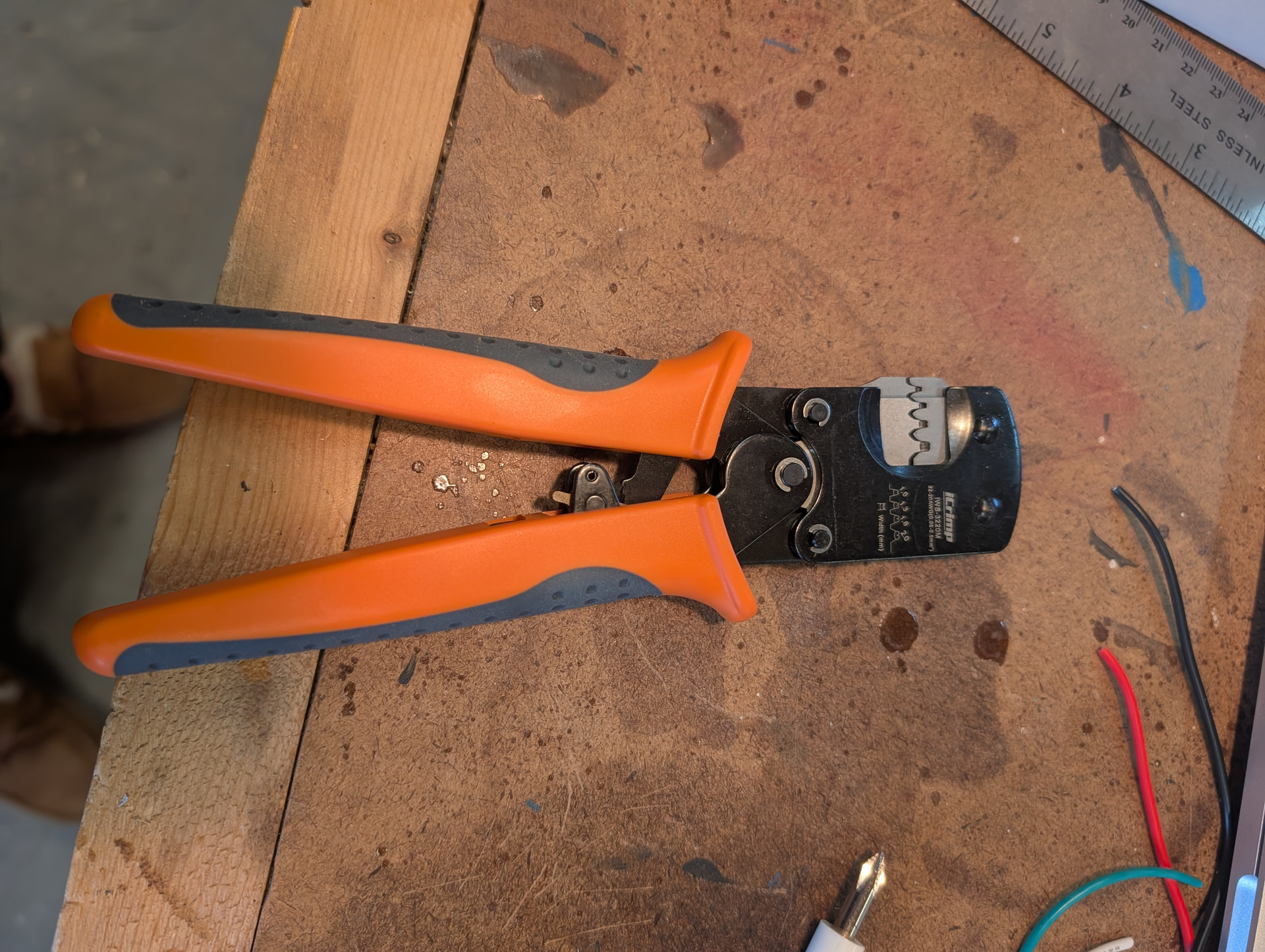
In other news, I finally found perfect crimpers for the JST XT connectors.
3 Likes

That’s the ones I use. Not the cheapest by any means, but they are the only ones I can get good crimps consistently with.
1 Like
Worth every penny. I threw out two other crimper I had bought in the past that never worked well.
I’m down to 3 crimpers.
2 Likes
Got the air solenoid wired up and tested this morning before work. It clicks on/off with the M8/M9 commands for ‘flood’ coolant.
I’m going to have to wire up a little board to make the wiring cleaner for the flood coolant and the touch probe. I’ll test the touch probe this evening before making the board.
I need to see if I can figure out how to modify the UI any to get the Air assist button added to the UI instead of having to enable the entire Spindle section.
If using WebUI v3, you can just enable the Macros section under Settings → ESP3D Interface. You can then just add a gcode macro.

I’m not certain but I think you can set the macro to #T-FLOODCOOLANT# to toggle it.
I’ll try that this evening. I was hoping to add the buttons direct to the laser section. But that will work too.