Having trouble with my build. Mpcnc primo, with a mks Gen L main board. I seem to be skipping steps, and having issues with it pushing one stepper further than another. I’m about at my wits end with this thing and would love some advice. I’ll post pictures tomorrow once it’s daylight out.
There are a number of reasons for this behavior, and you will need to give us more information to narrow things down. Here are a few things to check:
Are you sure both motors are working, or is it possible only one is working and dragging the other? Reboot your system, then electronically move an axis slightly to force the steppers to engage. Then attempt to push both trucks/steppers down the tube (lightly). If one is free and the other engaged, then only one side is being driven. Typically, this is firmware issue.
Is one or more of your pulleys slipping? The grub screws holding the pulley to the shaft are often the culprit for slippage.
If you are using DRV8825 or A4988 drivers, did you set the micro-stepping the same on both motors? Did you set the micro-stepping correctly? All jumpers need to be installed.
Do you hear any lost steps (sounds like grinding or buzzing)?
Is that a MKS Gen L v1.0 or v2.0? They are quite different boards.
I have a couple of the V1.0 boards and have used one with the MPCNC Primo before, though I switched over to a different board.
As above, make sure that you have all 5 motors engaged.
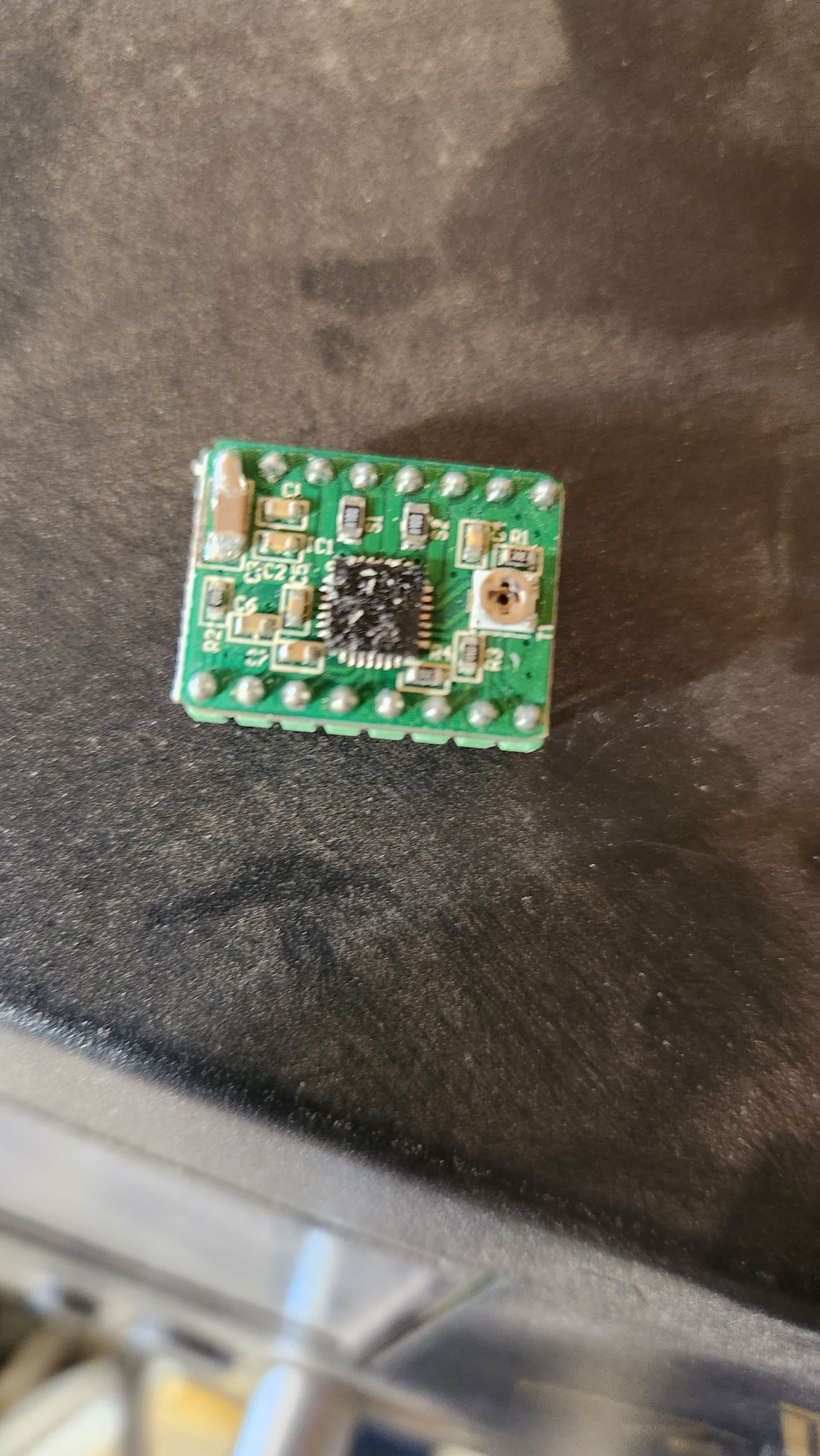
For the drivers, make sure that they are appropriately set for the amount of driver current you need. Check the documentation of your drivers, because they sometimes have different standards. The MKS Gen L uses polulo drivers where you need to set the Vref using the little trim potentiometers. My DRV8825 drivers are set to 1/2 the volts for what you want in amperes from the driver, so if I wanted about 1A current, I would set the Vref to about 0.5V. I believe that I had mine set about 0.6V for about 1200mA current while I was running the MKS board.
It is a 1.0. I have the steppers running through splitter boards, instead of each one having it’s own driver. Would this be causing the issues I’m seeing?
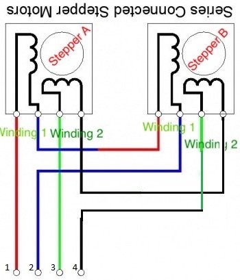
if these splitter boards run the drivers in parallel, this will be weak, and uneven. Parallel means that pins 1 through 4 on the output connectors are connected in the same order as pins 1 to 4 on the input connector:
This results in the OUTA and OUTB motors being run in series. We reverse the direction of the pins 3 and 4 in order to reverse the direction that the motors run, because on the Primo the same direction should have the opposite motors spinning in opposite directions.
The advantage to parallel wiring is that it keeps the max voltage up and allows higher speeds. the advantage to series wiring is that it keeps the current up and allows more power, but effectively divides the maximum voltage for speed in half. (On an MPCNC, this is a much more preferable situation.)
I would much rather run all 5 drivers on your board. Even if you do not run end stops, the 5 driver firmware is going to give you the best performance, and if you ever do run end stops, it gives you the advantage of automatic squaring and reproduceable locations.
Here is a wiring diagram for serial/series wiring as suggested by Dan. It is found under the “Archive” link on this page. If you are going to run with motors in pairs, this is the way to wire it, but I second Dan’s suggestion of giving each motor its own driver (five drivers in total).
Based on a post by one active member of this forum, parallel wiring can work. In the early days of the MPCNC machine, some machines were wired this way and were successful. The builders had to increase the current setting (VREF) for the driver boards to compensate.
Have you set the VREF for your steppers like this? While alternate wiring is better, I cannot help thinking that either incorrectly set VREF and/or a mechanical issue is at the root of your uneven stepper movement.
The V1 maintained firmware for the Ramps board (which I assume you are using as the basis for your firmware) is setup for the DRV8825 drivers, but the change to A4988 drivers. is simple (and does not require reflashing the firmware). If you are going to replace all of the drivers (as opposed to just buying two new drivers, I suggest the DRV8825 stepper drivers.
The first time I saw one of the parallel boards you are using posted on the forum, I went out and looked at pictures. Based on the pictures, it seemed to me that it would not be too hard to rewire them for serial/series wiring…cut some traces, solder a few wires…
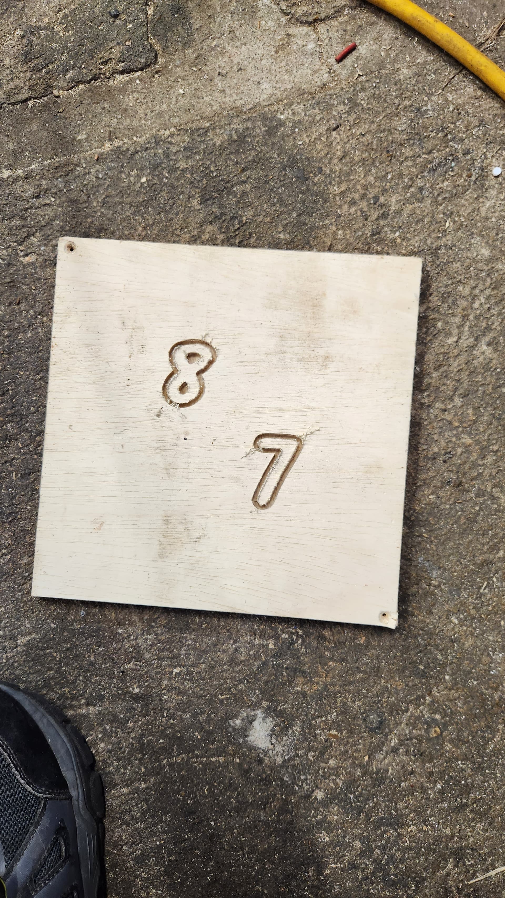
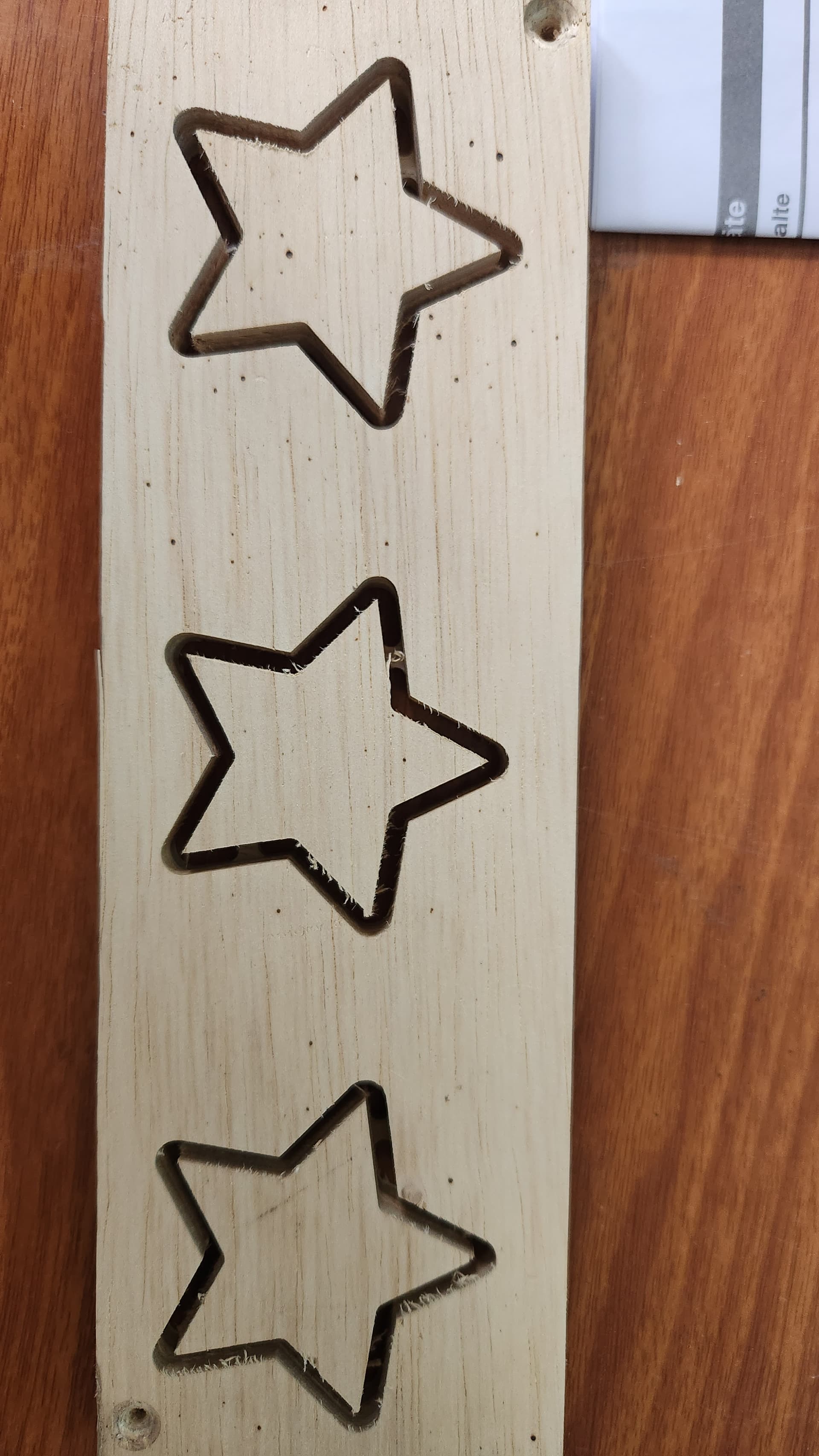
So! Got a new main board, still mks gen L, (fried the last one), new steppers, and rewired everything, flashing it to the dual endstop ramps. Now some new issues… The y axis doesn’t home correctly. It’s very inconsistent, and the end stops don’t always trigger. Triggering them by hand works though. Tried a cut I did the other day (clock) and it came out with no steps! But it was scaled way up. Probably more than 500%. I’m using vectric aspire, with the post processor from this forum. And then using repetier to send the gcode. I tried making a sign from scratch, and it just cut a random shape out of the board, so I don’t know what it thought it was doing there… Any more advice would be great
One of the end stops on my Gen L was a bit dodgy, and I sorted it out with a 1.5k resistor between the signal pin and the +5V pin on the end stop connector. I thought my pullup resistor had failed, but it was just weak. mine was for the touch plate, and if I touched the plate while using it, it would sometimes trigger because it could not hold logic high. This was a positive false, but because the stop switches are wired NC, you would get a failure to trigger from the same thing on the other pins. It may be worth investigating.
Do you have all of the jumpers installed under the driver? A new board might have come with them out, or not all installed. You need all 3 jumpers covered underneath the motor drivers. With A4988 drivers this should give you 100 steps/mm, with DRV8825 it will give you 200.
I can’t help with Vectric Aspire, I use Estlcam for CAM, and send the Gcode over Wifi to the SD card on the machine.
I’m having a hell of a time. Problem after problem with this thing. The end stops issue was as simple as reversing the end stop plugs on the board.
The machine is still randomly skipping steps, and one of the x axis motors has now stopped working. Going to see if it’s the motor, or the brand new board. Also… It seems the steps per mm is way off.it is telling me the work area is only 300mm by 300mm, when it is 24" by 24", which is about half the size it should be…
Random skipping steps if your motors are wires in parallel is going to be an issue if you cant bump up the total current. In series, 900mA to 1000mA is sufficient. In parallel you need approximately double that. Many A4988 drivers are only good for about 1000mA current total, which can be a problem with this configuration. Going with dual endstop firmware and 5 drivers is an inexpensive workaround. You can still run that without the endstops, or even use single endstops with a good wiring solution.
To troubleshoot the motor, swap the wires for the x axis motors. If the problem stays with the motor, it’s the motor or the wiring. If it moves, its the board or driver. Test the driver by swapping it with another that works.
If you doubled the current for parallel wired motors and one motor comes unplugged, you can overcurrent the remaining plugged in motor and burn it out. This is one of the big dangers of parallel wiring.
Install all the jumpers underneath. That will set the microstepping to 1/16
The steps per mm needs to be set to 100,100,400. M92 alone will print what the values are. M92 X100 Y100 Z400 will set a new value. M500 will save any changes over a reboot.
You have to set the current on the drivers.
There is no reason to wire them in parallel. I haven’t reread this whole thread, but are you sure you either have one driver per motor, or you have wired the double motors in series?
And the usual warning, watch out for loose grub screws.
These are some of the mamy reasons we don’t use ramps anymore. The rambo and skr pro handle all these features in the firmware. We configure it, you run it.
i just went out to test a different stepper, and it works again… and its not skipping steps somehow.
all 3 jumpers are under each driver
i am running 5 drivers now, not 3 and splitter boards like before
i checked the steps per mm, and it was x200 y200 z800. i reset it like jeff said to, and it seems to work better now. gives me roughly 600mm x 600mm area, which is correct. now to test carve?