I have been kicking around all sorts of new LR ideas. It is tough to commit to anything.
I absolutely hate that for some reason some builds don’t track. I have had two builds now, and without much real care put into making sure the side plates are parallel to anything less than a mm mine are dead on. To me this is as big of an issue as people not being able to square a 525 build. Plain and simple design flaw that most builds don’t need it. (people still have issues with the primo but on the order of 90% less). Meaning I built a machine that is too hard to assemble right/well enough.
Belt tension, parallel sides, bolt tension. I feel like we have looked into all of that any never find a smoking gun.
Wheels need significant force to move sideways, I have never ever experienced it. Even with a dirty table. If you ever did add a tiny bit more weight. I just grabbed my LR and slid my table and the wheels did not let go and there is no router in it right now.
The rails should not hit the side of the table if they do that can cause binding.
Now…the caveat here is I start my cuts extremely square. I use layers of tape to get precision hard stops. If you are even a fraction of a mm off, over 8’ you will notice it. The solution for that is simple…endstops. I just never needed them and did not want to add the complication of work coordinates or measuring from home to your workpiece.
The largest issue I have with rails/pipes/guides is your build is only as accurate as you make that one rail. The current design you can have s funky wobbly table and the machine drives in a straight line, even follows a Y axis arc if needed. Meaning you don’t have to be able to build a perfect table, and install a perfect rail. You only need a relatively smooth surface. How do you build a precision table and a straight and level rail without a CNC? For beginners that can be significant enough not to undertake the task.
Not sure what to do with the next LR when the Zen is done.
I’m generally a pretty careful builder, but then I imagine so is Jeff. Good to hear about the wheel traction too. I also had all those issues with my first ZenXY, so maybe I’m sometimes not as careful as I like to think.
There are lots of DIY CNC plans out there that start with “Get someone who already has a CNC to cut…” This is why I hadn’t already built something like a Joes 2006 CNC already, it required a CNC to bootstrap it.
Fortunately, I now HAVE a CNC, so I can bootstap it.
For building the table, I built the torsion box that my Primo sits on with a skillsaw, and plywood cut for me at the lumberyard. It would need different support than it has, but I don’t think that I’d have any trouble putting a LR2 on it, it’s straight and square. Way better flatness than I had any right to expect from those warped 1X3 pieces, too. I put it down on the floor, and it wobbled, because it’s flatter than the concrete of my basement floor.
Right now, one of the biggest things holding me back s the cost of lumber. It’s nowhere near as bad in Canada as in the USA, but lumber here has gone through a huge spike in prices too. Production is low, so prices are high. We’re seeing about the same sticker prices here, but of course in Canadian dollars. This is also the big hold-up with the legs for the new Zen table. What I wanted to do turned out to be unreasonably expensive, so I’m looking at a redesign for everything under the table top.
I think that it seems like a matter of build and setup. Once built and configured to work, it seems to continue to do so, but those who have problems… Have problems.
I’m sure you could do only 1 side. It would be easier in a lot of ways because you wouldn’t have any concerns with keeping 2 rails exactly parallel and would help if the table wasn’t perfectly square. The only issue is that if your tabletop isn’t flat like your rail, then you’ll add some Z variance over the length. Might be easier to match rails to each other than to an existing tabletop.
Yes absolutely. I epoxied mine but was going to do that if the epoxy didn’t hold up.
Very curious about this, can’t wait to see the developments!
I get that, but I think to a certain extent you get out of the machine what you put into it. I knew that the quality of everything the machine could possibly make would depend on how it was built, so I tried to be careful with keeping things as square and parallel as I could using non-CNC tools. I didn’t have a problem extending this to rails. I wouldn’t be looking for something to allow me to have a curved or wobbly table - but that’s just me. If one didn’t take the time to ensure the sides of their table were at least parallel, seems like they’d have built-in problems.
In defense of rails:
Rails are things I can shim or nudge up or down fairly easily, whereas table corrections mostly require starting over. In fact, I could decide to build a different table for whatever reason and just port the rails directly over to it.
Rails also let you have a wobbly table… just invest the time in getting the rails right and you have a flat milling plane above whatever table you use. You’re decoupled from your table. I thought my table build was much harder than my rails.
Rails free you from needing to dedicate a clean, flat surface for wheels on your table. My table is exactly 4x8, and I cut t-slots channels all along the surface of it for workholding which would not be wheel-friendly. I want to be able to throw sheet goods on without pre-cutting them. I couldn’t do that without rails unless I built a larger 4’4"x8 or so table to give room for the wheels. To get a full 4x8 work area, It’s much more challenging in my opinion to build a table with standard sheet goods bigger than 4x8 to accommodate wheels while keeping everything square than it is to add rails to the side.
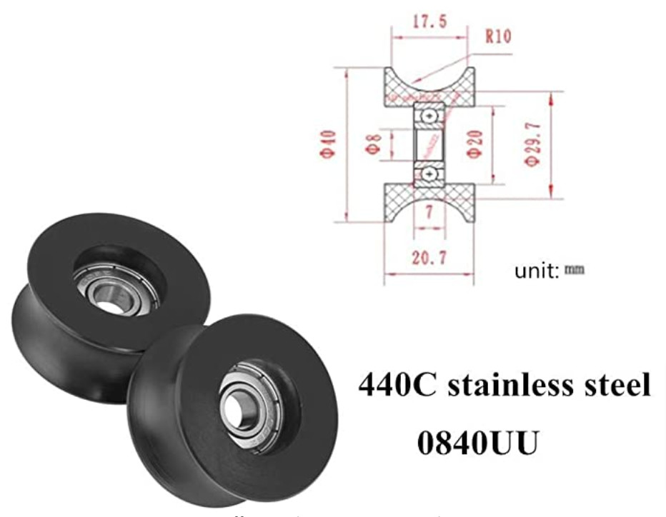
A rail is an option for the new build. I have CADed it up before, using a 3D printed wheel just like the one in this thread. I am just not sure it is the best option. This only fixes a problem some people has for a lot of added complication. I want to try to fix the complication first I think. You have to think these days actual linear rails are not all that expensive, so that is another option.
A lot of people just build a frame to the size needed, the wheels ride on the outer 2x4 and a single sheet gets screwed down on top in the center. Super simple clean and easy design. This is how I would recommend a new LR design be built with or without a rail. We most certainly overthought it in the beginning. I do use my LR table as a work surface as well though so I do not mind having a large shop table with all surfaces covered.
Is there a good way to build one rail, from a very straight source, at the same height as the other end, which is just on a flat? And then, is it possible to make it optional in case someone doesn’t want it (like dual vs. serial)?
IDK. The aluminum angle from HD was not cheap, but it came straight and was easy to install with a drill and some screws. I only worry that if I was a little less careful, I might end up with binding.
To me this is the hardest problem. I have lots of ideas for the actual gantry, some extreme, some not so much.
I really like the thought of someone slapping the LR on a sheet of plywood on a regular table and being able to cut most of another sheet, as in it could cut precision parts for its own permanent table if needed. I am pretty sure that is how printrbots large CNC was sold and that makes a ton of sense to me.
We have the guide rail, like yours Heffe. An actual rail like this thread(singular, wheels on the other side). Wheels on top and on the side (needs two good reference surfaces). Or one of many linear rails. Or metal angle or square tube with wheels or bearings. Or fix what we have.
I do like this, if you build a skeleton table like I had previously mentioned this leaves a 90 degree reference edge, sneak a rail right in there…could work.
New design option - the Sidewinder. Rail on one side, wheel on the table on the opposite. Just needs a “filler” on the wheel side to make up for the rail height difference?
Maybe the key is 60mm wheels (or, can we afford a larger, more common size, like 68?). If you want/need a rail, 3D print some V wheels that combine with 3/4" angle to be 68mm too.
Seriously, is there any reason why the 2 sides need to be at the same height? So long as the X rails are parallel to the table and have the motion ability to lower the tool plate into the work area, does it actually matter?
The thing I want to try in the future is using rails topped with double helical gear racks for linear tracking and drivetrain in place of belts. Printed some to test it out, but not ready to trust printed PLA for an actual build.
Even better if the different sets of holes are different sizes for some reason. It’d help make sure someone doesn’t use the wrong hole for the wrong design.
IE> Rails use the upper 5/16" holes. Wheels use the lower 1/2" holes. (whatever the real sizes are).