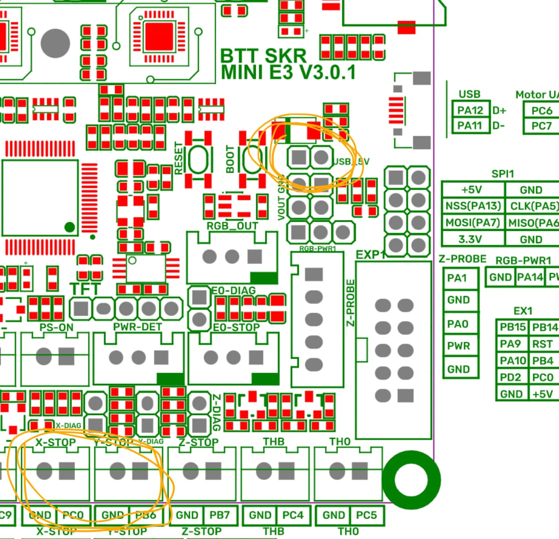
The pinout in the board tells me x and y stops have only two pins. One for signal another one for ground. The endstops have three pins: ground, 5v and signal. Based on that I connect the ground and signal from the board to the endstop and then I connect the 5v pin to the usb 5v in the board:
What test can I do to make sure the end stops work correctly? I was thinking I could run home X from Marlin and then trigger the end stop to see if that makes the board to stop moving the motor.
Those endstop boards are trouble. Our firmware, at least, is configured to wire the endstops normally closed. Those little boards usually default to normally open. The easiest remedy is to get some of the cheaper switches without the built in pcbs. It you can try to cut them off the pcbs.
I tried all the ways I could think of to “convert” the LED/PCB end stop boards to “normally closed” and couldn’t get it to work. Even though the switches have a normally-closed pin, the logic on the PCB and behind the LED and resistor sort of locked them into normally-open operation. I ended up cutting the switches off the board and using them “naked.”
 test firmware with board