FWIW I tried for about a month to get the SKR 1.4 working with LR dual end stops. Eventually I got tired of failing and just bought an SKR 1.3. Within an hour of its arrival I was up and running.
2 Likes
I kind of know what you are saying, feeling more incompetent than ever before with electronics 
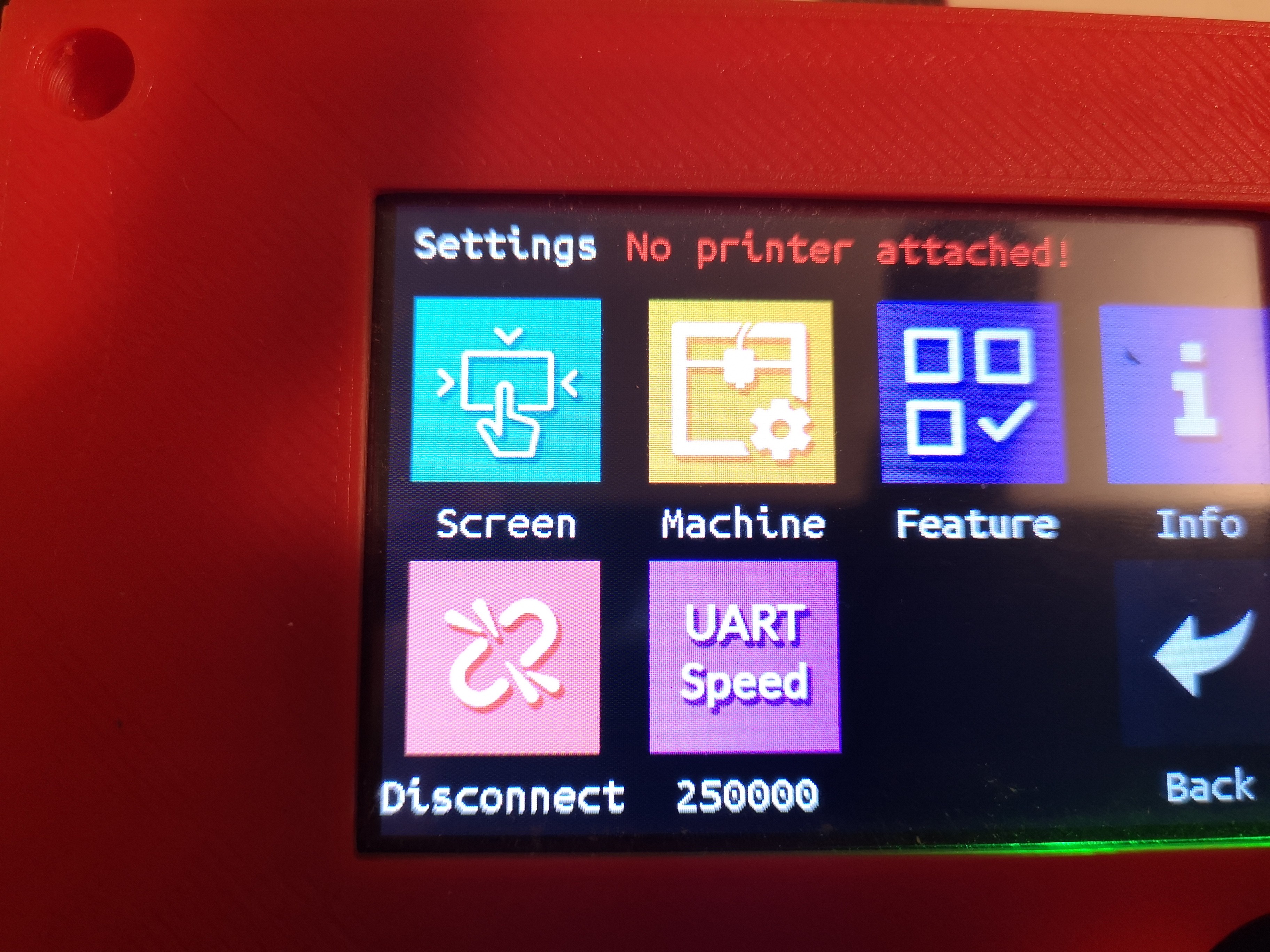
But you are on to something, the baudrate in configuration.h is set to 115200
Hmmm. Not the MarlinBuilder releases firmware.
So changing UART speed to 115200 made it work…Should i change it in configuration.h to 250000 or just leave it?
This firmware is configgured to endsstops NO, would it be a problem to change it to NC? i already broke my pins long time ago…
Any idea where the probe is connected? Found it P0.10…
And can the neopixel pins handle 12V PWM?
For practicality, 115200 is probably fine, just that if you’re looking for help here, we’re all pretty much going to assume 250000 is correct. Also, once you’re done, if other people are going to use this, they are also likely to assume that it will be in line with V1 maintained firmware, which is 250000
Hi Guys! I’m a complete newbie when it comes to the world of CNC. I’m just a woodworker so coding confuses the crap out of me. My goals are to have a CNC and Laser engraving setup. I currently have purchased the SKR 2 TFT35 E3 V 3.0, 5 TMC2209 Drivers and the SKR V 1.4 Turbo. I have also bought limit switches for my x and y axis’s and was hoping to be able to auto level when trying to get ready for each project.
When it comes to building it and putting it together I think I can handle that but when it comes to the computer side of things I’m lost. What file do I need to upload to my sd card to have these functions? Also, does anyone have a picture or a diagram of how they set up their laser to the SKR V 1.4???
The first post has a link to github where you can find the firmware.bin file
I am not sure with the TFT35 if you need a seperat firmware for setting that up? I did that long time ago…
If you use the firmware at it is you need to configure your limit switches NO (normally open)…
I am not sure about how the old issue with the TMC2209 driver pin that needed to be bend is?
Regarding laser. If your TTL will understand 12 V PWM where the ground connection is modulated FAN 0 works, my NEJE 30W module dos not and just see the +12V on the plus and give 100% no matter the setting… i have not figured out the Neopixel connection yet,
I am kind of lost in getting my Neje laser to work, it needs 12V TTL, so on the FAN0 the PWM is on the ground, so that dos not work.
The 1.24 PIN is 5V…and i seem to measure it being constant 5V?
So what is the easiest path to get proper 12 V PWM?