Stepp/mm change over time

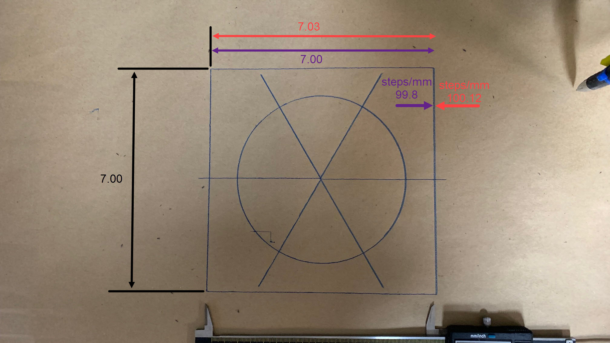
Before I flash my firmware with a new steps/mm value I am curious if there is anything mechanical that could account for a change over time? Way back (few years now) when I first built my Burly machine I verified accuracy and found I needed to increase the value for X slightly to get accurate output. Never went back and checked again since TBH. Recently I was trying to machine a two sided Delrin piece for first time and found out that it is no longer accurate in X and the value is off in the opposite direction so two sides didn’t line up. The FW default value is 100, my old value is 100.12, and the new value appears to be 98.8 set with LCD). So on a 7" square I am getting 7.03 X and 7.00 Y. With the change I get 7.0 on both X & Y again.

Thinking about what I have done to the machine over the years, could belt tension, or bearing pressure account for the change (I have had to adjust both over time)? Could the steppers themselves change over time (i.e. get tired? I have disable the idle time out so they will occasionally sit powered and holding position for hours or days while a job is paused or a set up is being done. Never notice over heating or anything).

FWIW, I am running a dual end stop set up with a RAMBO 1.4.

1 Like

There are exactly 200 steps in the stepper motors. They have an array of magnets, and unless you took one out, they won’t change the number of steps.

The drivers convert microsteps to full steps. The little driver boards never miss a step, you can consider them perfect. There are always 16 microsteps for one whole stepper step.

The teeth on the pulley are exactly 16. There is not a way to get or lose a tooth (well, you could lose a tooth, but it wouldn’t change the spacing).

The belt has rubber teeth, one every 2mm. It has fiberglass inside, which takes a lot of force to stretch. But it doesn’t lose teeth or gain them. The 2mm spacing per tooth might be 1.999 if the belt was very slack or 2.01 if it was very tight.

If you have white belts, those have steel reinforcement instead of fiberglass. Those can have fatigue hardening and crack inside the rubber, because we are pulling them around very tight radius idlers. If you have white belts, buy some fiberglass ones.

Those are all the components involved in scale/stretch accuracy. The other two sources are flex and backlash. Flex is caused by things like a cracked part, or CAM causing loads too high, or bit flex, stuff like that. Cutting a finishing pass can eliminate the flexes (except cracked parts).

Backlash is things like a loose grub screw. Moving from left to right and then right to left causes the first little bit of rotation to get lost (because it is picking up the slack, or the grub screw is moving across the flat of the motor shaft). Loose parts, or grub screws are the normal cause. Running a test to specifically check for back lash can help.

Typically, I don’t like changing the steps per mm, because measuring things like a 7mm square includes scale, flex, and backlash errors, but only corrects for scale. If you do a calibration at 7mm and then another at 70mm, you get different results.

3 Likes

I’ve seen several topics come across the forum over the last couple of years where, like your machine, measurements are off by just a small amount. Typically, they do what you did and make a minor adjustment in steps per mm and move on. I’ve always thought there must be an underlying mechanical issue, and the fact your machine changed over time bolsters that idea.

Things to check. Some are far out wrt your problem, but it only takes a few minutes to check them.

  • Did you verify the measurements with a pen? How do the measurements change with the size of the square?
  • Have you checked the tramming of your machine?
  • Have you checked for play of the Z axis and the core?
  • Have you tried to adjust the belt tension to see if it changes the cutting? I would not expect it to make a difference, but it would be a simple test to run.
  • Have you measured the bit width with calipers to verify the diameter matches your CAM?
  • Did you look at the g-code to verify it is cutting the correct distances?
  • Have you checked the grub screws (as Jeff mentioned)?

If you were cutting wood, not Delrin, my first thought would be the grain of the wood was deflecting the router bit differently depending on the grain direction.

Could the steppers themselves change over time (i.e. get tired?

Given how they work, I cannot think of any way the steppers are the culprit.

1 Like

A better test is an inside cut (hole or pocket), and an outside cut. This is an easy test for all sorts for things. Outside only makes you assume it is steps, inside and outside can show run out, steps, slop in general.

If your machine is mechanically off the pocket and outside cuts will both be too large, other slop will show numbers that disagree. small hole large outside cut.

1 Like

Thanks for the inputs!

  • I have run a couple pens tests to verify the issue and it is pretty consistent. So far I have only checked with 7 inch square and some smaller circles because of my immediate need to get accuracy at that scale. In the beginning I had used a larger pen test. Something like 12 or 16 inches as that was the max I could measure accurately. Those early tests dictated the initial bump up in the value.
  • I do have a taller than normal Z so it could be some of that, but a pen test is almost no load so I am guessing it is something else. There is not a lot of flex though.
  • The GCODE does appear to be correct (I use ESTLCAM and as far as I can tell the numbers are correct. The pens test code is for sure correct. The delrin code is complex but appears correct when run thru a simulator).
  • The grub screws are all tight.
  • Belt tension was recently adjusted but not the first time. They are somewhat tight now and I will need to try different tension to see if it changes anything. They are fiberglass belts.

That is highly unusual in itself. You should do the absolute largest test you can and measure the diagonals and the straight sides. The pen should be the lightest touch possible while still making a mark. That will test the machine itself. As I mentioned in the last one though the cutting test, pocket and outer, will tell us just as much as a pen test, so do them both.

A picture of your build will really help we are all flying blind and making guesses. For all I know you have a 2’ vacuum extension and cable chains on your Z axis and no amount of firmware changes will fix that.

by how much?

7lbs no more.

1 Like

All good points. I do have a vac hose, but for the pens tests it was not on. You can see it hanging on the wall behind the machine along with the router. The last machine image shows it roughly in place for illustration only (in practice the nozzle mounts to lower router mount. I have the hose supported in the upper back on a cross bar, and then on a very loose swivel atop the z axis motor (to help reduce any drag effect). But again all that was off for the pen tests. Not sure how much taller the z is exactly. I have 3.7" max clearance below the Z carriage, and 1.5 above the carriage to the Z lower clamp (without an router/spindle attached). Above is where I added a little Z height from what I recall (in case I wanted to raise the whole thing or drop out the spoil board for tall stock).

I will say the pen test probably had a bit more pressure than you describe. Crappy pen. I will try and find a better pen and re-run and do the pocket tests (is there recommendation on that test i.e. geometry, DOC, material, speed etc ).

I’ll have to figure out how to measure that 7lb to see how taut that feels. Seems I may be more than that. I am also including an image of the pen test for reference. It was run four times on top of itself. With original setting (100.12), set to default (100), set to new value (98.8), and a repeat of the last. All from same reference zero.


gel pen is amazing. Hard pressure in the pen Mount can flex millimeters.

You have both the worst examples I could think of. I know it is not on for the test, but the drag chain is. Anything on the Z motor is the absolute worst thing you can do to these machines. If you are worried about a 0.12% error, you should be worried about touching the Z stepper.

You can be at 20lbs and stretching your belt, 0.12% is not much.

You need a fresh piece of paper so it does not influence the pen, or very thick cardstock. Also you should make every square the absolute largest you can.
Does a 14" square have the same error as a 7" square or is it double?

That paper is too rough, or the surface is coming through. You need to draw on a smooth surface, mirror, smooth MDF? The center of that circle shows how much pen error you are getting.

I know this is a lot but you are asking about a very small amount of error. 99.9% of the time, it will not be step adjustments.

1 Like

If you want to keep that drag chain you should rotate it 90 degrees and attach it the core clamps. Standing up is no good.

1 Like

Jamie has a pen test that draws a ruler in two directions. This is good at seeing the backlash: G-Code Test Pattern Generator

To measure the scale, you don’t need the whole line, just the corners. It might do better just doing from the sky at the measurement point.

4 Likes

Very handy. Much easier to make changes than drawing it out, converting, etc. Thanks!

1 Like

Thanks again for helping to resolve this. In my tracking down the issues and testing, it seems to me it would be best to not drag this one out. The machine has more issues than this and I think a rebuild is in order. FWIW, I did re-run the pen tests and found that I had same results even when using a better pen and paper as you described. Adjusting the steps worked that same to correct the X accuracy. However, I also determined by redoing my X belts completely and setting the tension to be more reasonable, I got back the X accuracy and the steps/mm could be set at the default. So I must have been too tight?

I am not convinced this was the full cause of all my dimensional issues with the Delrin project but it could explain some of it. I had run that job twice. First time was a too aggressive DOC and the bit was pulled into the work and damaged the piece significantly, but after resetting with a more conservative DOC, it finished OK. It did not have the same dimensional issue so something changed in between the two attempts. Maybe somethings cracked where I cannot see it.

I also ran the cut tests you described after I fixed the belt tension. All the dims are off as you predicted with the flex. I can feel it flex when manually pushing and pulling so I will have to track all that down. During the pen tests I found I could move the pen in the Y by pressing on Z stepper lightly, but not really at all in the X unless I skipped the motors (hard to do). Weird. Below are the cut test I ran.

Bottom line is I think I am coming to the sad realization that it is just not rigid enough to do what I was attempting. We carry on. Maybe a PRIMO or BRUTUS is in my future.

1 Like

Yeah, like by a lot.

Are all of those cuts down with a 5-10% finishing pass? There is now way this is not accurate enough if wood or delrin. Something major has to be wrong. If the mpcnc can’t hit it you need to think about at least a tormach. Nothing else is more accurate, you might find some a bit faster but the accuracy is the same.

What tolerances are you trying to hit? I am seeing as is you are hitting within 0.3mm. That is really good in wood. Delrin will give you much tighter numbers.

Just know. Perfectly adjusted, to get really insane tolerances you will need to compensate the model to account for runout, getting really crazy you need to start accounting for temperatures (if you are worried about that you need to add 3-4 zeros to the pricetag).

1 Like

Yes the pocket cuts were all done with a finishing pass. (some were run twice). I think I left 0.5-.6mm (.02").

For the Delrin piece, I could live with +/- 0.5mm . And as I said what I am showing is probably fine for 99% of anything else I would ever do. What I got on the second attempt with Delrin though wasn’t so much a tolerance issue as it was a variation in the X axis. Meaning I was machining something circular but it came out as an oval (approximately 0.8mm over size in the X dir, but since my zero was 3.5" from the center (@ corner of my clamps) the error was stretched out. When I flipped over for side two that error doubles and when side two was finished (also with same ovaling) I lost 1/2 my final wall thickness on +X side of the part and no machining at all on the opposite wall (-X side of the part). So yep. Something really wrong. I attributed it to a change in the steps/mm as that was what I was seeing in the pen tests. Maybe it was just the belts or something else unidentified. If I get up to it, I may try again but material prices being what hey are, I may leave it to the pros with the Tormachs!

I know I built this guy too large to expect it to be all that rigid and it was built with conduit. I can practically flex the x rails with my hands. LOL. Now if only I had room for two machines to play with. :wink:

Thanks again!

That should be very easy. Not an issue on a machine of your size. If you had ovals, either you are not starting square or your belts were way unbalanced between the two. The extremely tall Z axis the hose and drag chain attached to it are the most worrisome thing to me.

The machine is running on two rails on each axis, It will easily support your full weight. The LR axis is 4’ with two rails, no issues with tighter tolerances. I know it was a joke but I need to clarify for future readers, it is not an issue. To be specific I had a 3’ piece of 1/2"emt I thought I could bend it over my knee, 4 days ago. I had to take it to the curb and stomp it to bend it, 3/4" is much much stronger.

My suggestion. Use the instructions and back up a little bit. You are at the point where you want to buy a new machine.Try changing a few little things first. Cut the z axis down to the minimum, make sure your axis sits fairly square and all bearings are touching on the gantry with equal tension. Remove the drag chain and use the tape measure trick, do not let anything touch your Z axis above the core clamp mounting points. Then verify your homing procedure and how square you are getting it.

1/2mm is an easy target, something basic is not right.

3 Likes