It works with the common cathode! Thanks Tim 0.
2 Likes
You’re welcome! Glad I could help!
This morning it wasn’t working anymore. After a few fustrating hours I almost wanted to give up. Because it was a test set-up I used 22AWG stiff wires, that was a bit dodgy with all the jumpers. So I decided to do it properly and use some silicone wire and put ferules on them… then it worked again the common anode way.
The only thing that is strange is, I can’t use the jogging controls in CNCjs and when I give it a manual command, for example ‘G1 X100’ the pulley turns right for a while, then goes back (left) for a little bit and then the same distance right again. When I give it a G1 X100 F2000 command it turns only right (correct way). What could this be?
Also because I was a bit frustated I also tried a smoothieware firmware.bin file and there it behaves correctly, I can jogg and I can give it manual commands.
Anyone knows what could be wrong in Marlin?
Hi guys I’ve got another quistion… I’m trying to get my MPCNC working with LinuxCNC as I already got the drivers and I only needed a 5 Axis Break out Board, so I bought one.
I connected a 5V relay, the same one in this post, to trigger the Makita RT0700C spindle with M3/M5.
I got it connected up the right way, the only problem is the output of my BOB can’t trigger the relay (probably too low mA). it works when I connect the ‘IN’ on the relay to my 5V power supply, so I know it’s connected the right way.
Do I need to UP the mA on my BOB’s output and if yes how?
What relay is it? Most relay boards use a 5V in for power and just a 5V signal for control. A plain old relay needs some surrounding bits (a transistor and a diode, at least) to use.
Something like these:
But if you search for “Arduino relay”, you usually get a lot of good cheap choices. You would connect the output from Bob to the signal pin and 5V and ground from the power supply.
it’s this relay:
(5V 12V 24V One 1 Kanaals Relais Module 30A Met Optocoupler Isolatie Ondersteunt Hoge/Lage Niveau trigger Met Geleiderail - AliExpress 13)
Yes this one also use 5V for power and a 5V signal, but I’m guessing my 5V signal from the BOB doesn’t output the needed Amperage?
The reason why I chose this relay can handle high current, which is better to work with the spindle right.
I also have those cheap relay’s, haven’t tried that yet as I preferably want to use this one.
That relay looks fine.
That should take basically zero amps on the signal. You can confirm with a multimeter. My guess is the bob isn’t actually toggling that pin. I would test these things:
-
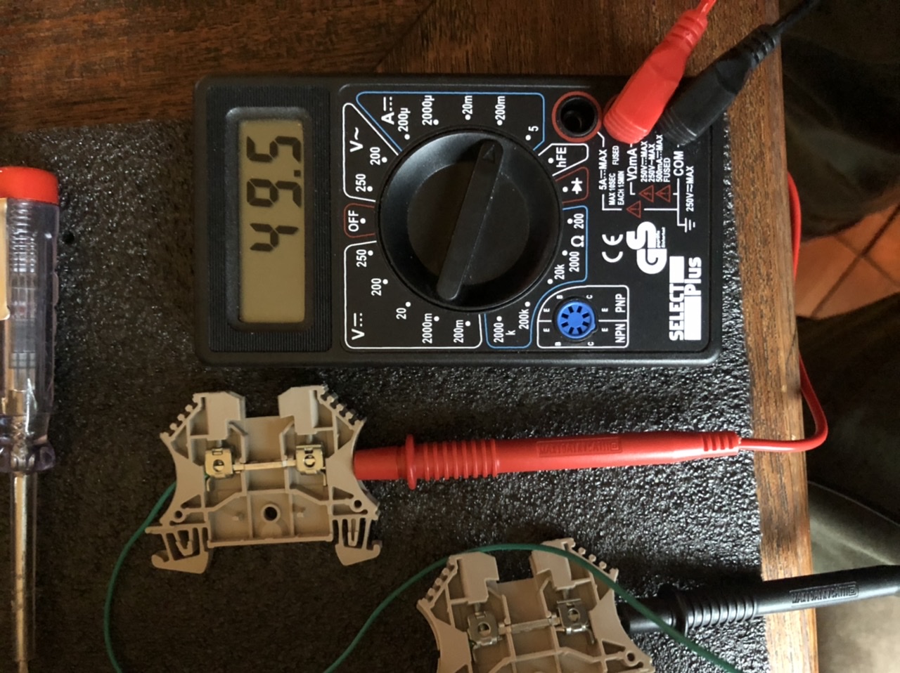
Using the voltage meter setting (make sure your leads are in the right place), does the bob output 5V and 0V, relative to the same ground used on the relay? Measure from the bob output to the ground on the relay.
-
Using the current setting (make sure your leads are in the right place), how much current goes from the power supply to the signal input when it is turned on? It should be very small, 1mA or less. Remember to put your leads back on the voltage side

1 Like
Oke what I did is, put the multimeter between the 5V power supply and the ‘IN’ on the relay. The relay triggers and the reading I got when I put the switch on 20m, is 1.3. So this means the IN pin draws 1.3 mA right?
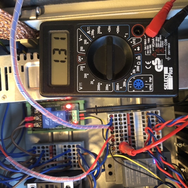
Yeah. That should be small enough for any output.
1 Like
Oke I found the problem… I used the 5V power supply to supply power (+ and-) and I connected the BOB for the input… but I also need to connect the +/- to the BOB