At work I have colleagues who are electricians, so I can ask them. But know with this COVID19, I don’t see them as often…
I’m also looking for tutorials for an electronics enclosure and there are a lot. But I have a hard time finding in depth guides and tutorials, anyone has some good tutorials?
you could always try sending them pictures of the completed wiring, not as good as seeing it in person but its better than nothing  also are you looking for a how to make the enclosure? or rules on how to make it safe?
I have an offcial electornics enclosure 40x30cm, but I would like a tutorial about what the possablitities are to put in it… like a relay, emergency stop, a led light, fans and other stuff.
What I have so far is a MKS Sbase board and a 24VDC MeanWell powersupply… but they are not in an enclosure yet. I also bought some GX16 aviation pluggs to connect the stepper motors and a plugg for a USB cable.
ahh well for designing your enclosure is largely personal preference. i used to design industrial controls for HVAC equipment and even in the professional world there where 1000 ways to approach it, limited only by the codes and certifications you wanted it to have (here in the US that was mostly ETL, UL, and NEC). my recommendation is to do your research, find one that you like (look, usability, price range, and skill level) and copy that general design. there are some really good examples of enclosure builds here on the forum. so spend some time looking through the “your builds” section (both for the MPCNC and LRv2) as those will have most of the electronics and options you will have on your machine.
the most common things i see, are options for the screen, plugs for all the wiring, and E stop buttons/switches.
Thanks, I will do some research!
I have a question:
I have a MKS Sbase board which takes 12V-24VDC, and I got it powered by 24VDC.
If I use the the BED, E1, E2 and Fan connectors… is the output also 24VDC?
So if I want to connect a fan for example, it has to be a 24V fan?
1 Like
Yes.
Yes. 24V DC fan.
There are other pins that have very little current capacity, but they will be 5V. If you just need a digital signal at 5V, you can use one of those and turn them on with M42.
2 Likes
Thanks Jeffe,
I ordered some mechanical relay’s, the same one as you suggested just a different brand.
Now I found this:

it’s a picture from this web page:
http://microfabricator.com/articles/view/id/53a548013139440e2c8b456e/shapeoko-upgrade-quiet-cut-spindle-with-gshield-and-relay
So I need 3 pins from my board, 5V, GND and a digital pin… so how does it translate to my board?
A 5V and a GND I can find… but which one are digital pins?
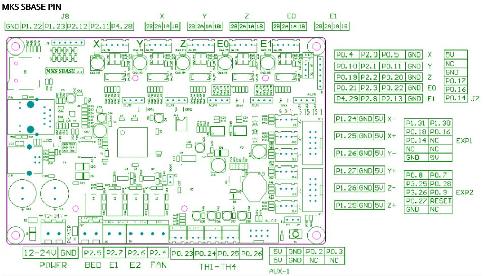
Whatever one you want. I would personally use one of the endstop pins that I didn’t need. That has 5V, a pin, and a ground in one spot.
2 Likes
Thnanks, Yes I thought so too!
1 Like
Today I will recieve my 24V LED strip, I will put this in my Enclosure to get a lot more light in. It’s pretty dark now.
So I want to connect the LED strip to the BED/E1/E2 pins, the FAN pins I want to use for my fan(s) who I ordered. The LED strip is just a (warm) white color with black and red wire. Can I just connect it to one of the outputs (BED/E1/E2)? And how do I turn them ON and OFF? And do I need to set something in the firmware?
You might be able to toggle it with M42, but I doubt it.
There is a bunch of logic and protections around the heaters (which is totally reasonable for a 3D printer).
One way you can for sure do this is to change the pin assignments for those functions to something else and then add these pins as extra fans. This would all be done in the pins file for your board and you would need to recompile and flash the board.
Oké Thanks! I will have a look after my 400 coasters are done, as I don’t want to mess things up. In the meanwhile I can also connect it directly to my 24VDC power supply right?
Yep.
1 Like
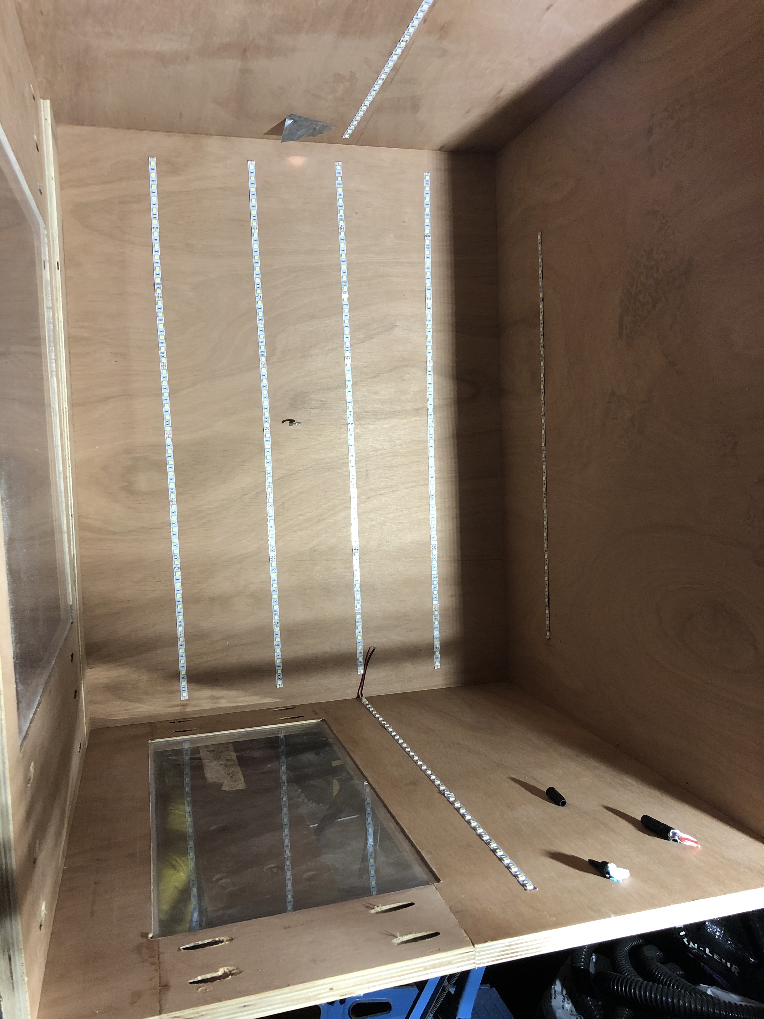
Oké I received my LED strip, I cut it in pieces and sticked them inside my enclosure.
Now my question is, do I need to connect them from start to end… or can I start in the middle (I think yes, but just want to be sure). I want tot connect them by soldering with wires.
In the photo, the enclosure is on the side… so at the top off the photo where the strip is going out side the photo, that’s going to be the start ( from the power supply)
Then going down I’m in the middle, 2 strips right, 2 strips left and 1 at the bottom.
So do I need to go far right and go left, or can I go right and left at the same time.
I hope my question makes sense…

i’ve seen that video, but it doesn’t answer my question.
I’m searching on YouTube, but now I think I know what to look for… parallel connection.
I’m looking for the best way to connect the strips together.
I would use the ones shown at about the 50s mark. https://www.amazon.com/dp/B07RG6T1FV/ref=cm_sw_r_cp_apa_fabt1_AgfSFb71Y8S4C?_encoding=UTF8&psc=1
I think in this situation it’s entirely up to you and the materials you can source and or have access to.
I did one long strip and just folded it to make 90 degree turns where I need.
I think I know how to do it… I will wire them in series. BTW nice build