SKR Pro 1.2 "No Printer Attached", broke while wiring fans, was after 12V to 24V upgrade

Did I just kill my SKR Pro 1.2 board while trying to upgrade from 12V to 24V? 1.2 and Octopus boards seem to be same price now? Green D22 LED is lit up, trying to find what that means… Suggestions appreciated, cheers!


How to kill your SKR Pro 1.2 board:

  • First, successfully upgrade power adapter from 12V to 24V

    • Turn power supply off, left connected so grounded.
    • Disconnected two 12V fans connected to SKR’s Fan 0 pins.
    • Upgraded to V1E 24V power adapter. Disconnected barrel jack, used WAGO connectors to wire 24V power. Checked and double checked polarity before wiring up. Super easy.
    • Powered SKR Pro on. Marlin booted, V1E ESP3D/ESP01s was able to connect and I was able to wirelessly jog. Great!
  • Now, reach for the sun, and fail

    • Trying to wire up Fans at 3am is where things went wrong…

    • Turned off again, wired up SKR’s Fan 0 pins to a cheap tiny efficient DROK buck converter (24V to 12V, claims up to 3amp…). Wired up DROK voltage input to Fan 0 pins. Left Fans disconnected for now, wanted to measure DROK output before risking my precious Fans :man_facepalming:

    • I didn’t check DROK component was functioning correctly before connecting to SKR. Thought about it, but decided to risk it… Ugh.

    • Turned SKR on, Marlin booted, ESP3D/ESP01s was able to connect, sent Fan On command. Nothing… Started checking voltages…

    • Measured 24V for Fan 0 == DROK voltage input. Expected.

    • Measure 0V for DROK voltage output. Unexpected. Guessing DROK fail or bad soldering by me. Visually and resistance checked DROK’s through hole wire-to-board connectors.

    • Wondered if Fans need to be connected and draw current for DROK to work. So, reluctantly wired DROK’s output to two 12V Fans (in parallel).

    • Short burst of strange noises, SKR Pro rebooted, I tried to disconnect but too late. SKR Pro doesn’t seem to boot.

    • Tried burning firmware, doesn’t update, remains firmware.bin, not seeing rename to firmware.cur

    • Will try blowing with compressor air later today.

    • Fuses have 0 resistence and they look ok.

    • Can’t see any damaged chips.

    • Checked TFT/Serial cables are secure.

    • PC doesn’t register USB port, so unable to connect from Repetier, doesn’t connect.

    • TFT and ESP3D both unable to connect via Serial to SKR Pro.

    • ESP3D has power, boots up, can send commands, but doesn’t get OK response.

I regret wiring like this at 3am, I should have ignored Fan 0 pins and tapped into power supply directly at the WAGO connectors that connect pigtails/jumpers to the SKR board’s input power pins. Fans would always be on, but the board would still be working if cause is excess current draw from, or, short of Fan 0 pins while I was trying to troubleshoot.

Don’t blame yourself. If you shorted the fan pins, a fuse would blow, or a mosfet, or a trace on the board, or your power supply. The skr microcontroller should be fine.

I don’t know what happened though. It sure looks like something with either a 5V power supply or the actual st chip is cooked. I don’t know how the fan could have done that.

The only other advice I have is to try to disconnect everything and try again. Maybe an endstop is shorting or something.

1 Like

I can’t see anything wrong in your procedure, so difficult to say what the root cause was. Maybe it would help to share some detail about the DROK and how exactly you connected it to the board. The fan connectors seem to directly connect to the power supply as per the BTT manual.

I guess you wanted to use the 24V for your stepper motors; so you could have kept your 12V line to supply the board itself, including the fans. No need to use a DROK then. My understanding is that these 2 voltages can differ, e.g. 24V for the motors, 12V for the board.

Maybe try again with your previous 12V setup?

1 Like

D22 LED for Fan0 lights up as soon as the board gets power.

From BIGTREETECH-SKR-PRO-V1.1/SKR-PRO-V1.2.PDF at master · bigtreetech/BIGTREETECH-SKR-PRO-V1.1 · GitHub

Hunting around the board for components between Fan0 and PWM PC8. Going to try snipping some parts to isolate buggered components.

So, current plan is to waste a bunch of time faffing about with a scope, then eventually realize my electrical limitations and order a replacement board :slight_smile:

I’m wishing you luck. You might be ok if you have a voltmeter…

I’d bet on Q7 being toast just because the solder pins look funny in the picture and from the diagram above, if Q8 zener fails, you have a path to ground from 12/24V or if P7 pins to 5V, then it would be on. If you can measure the voltage on both sides of R89 that might provide some insight.

2 Likes

Cheers @orob! Have some voltmeters that could help, measured in bunch of places, your failed zener theory (Q8) in the mofset seems to be what’s happened, plus who knows what else… Don’t know if transitor (Q7) failed, PC8 was 0V and VCC_5 was 5v, I used Q8 S as gnd to measure. I ended up removing Q7 anyway, hoping working/failed Q8 would get pulled down by R87.

Powered off before, and powered up after, each of the following things I tried:

  • Removed Q7 (same snips used to cut 3D printer filament), still repro
  • Removed Q8, D22 LED doesn’t turn on anymore (expected), but controller still unresponsive.
  • Captured video/photos (to help with assembly), removed all wires, still unresponsive
  • Removed all wires except TFT, still unresponsive (printer not attached and ESP3D gets no ‘OK’ response from Marlin)
  • Removed all wires except power, tried wireless gcode ESP3D/ESP01, no ‘OK’ response.
  • Powered off, removed all wires, cleaned with compressed air (6 gal pancake compressor from home depot).
  • Reconnected just power, ESP3D/ESP01 spins up, tried sending M119 and M114 commands to Marlin, but not seeing response. Reaching my electrical limits and leaning towards a future and involves Octopus…

Looking for debug serial port before giving up on this one…

out of curiosity, does it work without the esp? Wondering if you can clear off anything else like the stepper drivers that are easily removed. Power it via the USB to see if the 32 bit chip is toast or if something else let go. Did you try reflashing before you disassembled the board?

1 Like

Thank you @orob, great ideas, just tried them all. Did try reflashing before dissassembly, but processor didn’t change the firmware.bin to firmware.cur.

Hit my limit. Currently figuring out whether this is a good opportunity to try out Octopus or something else…

Bummer. I’m sorry for your loss. That pains me to lose a nice board for no really good reason. Any idea what the failure rate is on the skr line of boards?

1 Like

Not sure about failure rates. Personally, I liked the board and blame myself. Things I should have done differently:

  • Not do this at 3AM. Hardware breaks are (typically) more expensive than software compile breaks.
  • Should have been more cautious while troubleshooting when board was energized.
  • Should have wired fans to power supply instead of Fan 0.
  • Should have tested buck convertor independently of the control board, BEFORE integrating.
  • Shouldn’t have used the buck convertor even. Already had a 12V power adapter, should have used that for the control board, but 24V just for the motors. Ugh…

Guessing there’s more lessons here. Would appreciate advice from folks? Not ideal, yesterday I was drag racing, today, it’s dead Jim, LOL. There’s an opportunity here, and lessons for me, hopefully others benefit, and/or are entertained :slight_smile:

Cheers!

If you’re trying to power it via USB. You need to move the jumper.

Remember to move it back when you are back on 24V.

When you are powered via 24V, do you get 5V on the break out headers? What about 3.3V?

I still don’t see how that buck converter could have killed the mcu.

2 Likes

You removed Q8 off the board and the D22 LED was still lit??? Did you have anything plugged into J66 (FAN0 socket) at the time?

Use the tft port as a rudimentary serial debug port…

1 Like

Oh no, I meant to say…
“- Removed Q8, D22 LED doesn’t turn on anymore (expected), but controller still unresponsive”

Thanks for the power jumper tip Jeff. Just tried, but same result (tried 2 diff USB cables, and serial via ESP3D/ESP01s, firmware.bin not renamed).

With USB supply, 5V breakout pins are 4.24V, and 3.3V breakout pins measures 3.03V
With 24V supply (and power jumper switch back to original position), 5V breakout measures 4.82V, and 3.3V measures 3.18V

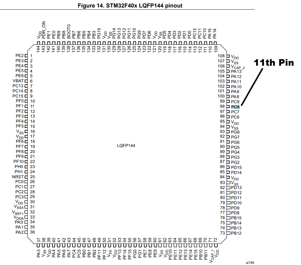
Found MCU pinouts, could just about probe VDD and VSS voltage on the MCU’s tiny legs, seeing same power going to the processor that was measured at the 3.3V breakout.

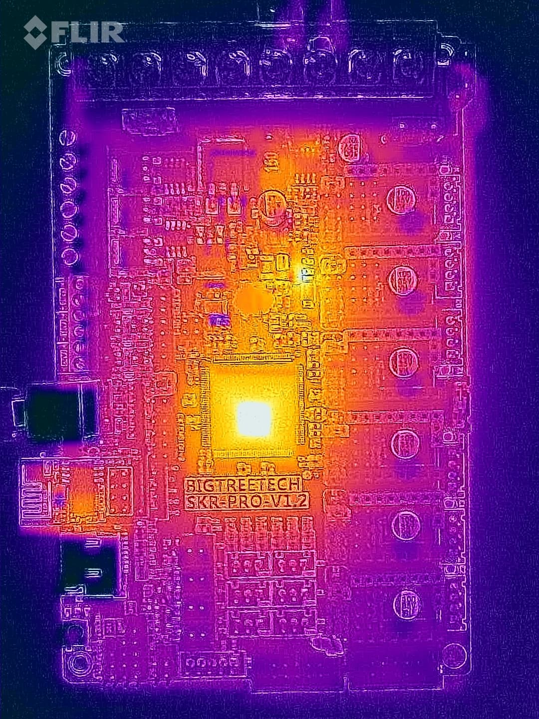
Tried hunting for unexpectedly hot components, didn’t see anything. Position of heat sources isn’t calibrated with blended camera image very well, but heat is coming off the regulators and chips as expected.

Appreciate all the help/suggestions. Learnt a bunch, but unfortunately I’m unable to take this further.

Thinking back to moment of the event… I might not have connected ground first, before connecting power to DROK.:man_facepalming:

Dug around for STM32F407ZGT6 datasheet and very very briefly contemplated ordering a ~$11.50 replacement processor.

Will probably ditch the DROK and use both the 12V and 24V adapters from V1E on the next board. Gantry has enough internal room and the adapters are light. Replacement is on the way…