Scara Coffee Table

Hi @Dito, really nice looking table you’ve made! Intrequed that you’re using klipper for running the arm, that made want to make one aswell. Im currently designing my own arm, heavily inspired by Rob’s design; This is my first real electronics project i’ve tackled.

Looking at the electronics from your table, and then mainly the picture from below, it seems that you have quite alot of electronics built in. Do you run anything else specific for this arm on the raspberry pi? I currently have a 3D printed which i’ve adapted from Marlin to Klipper and would be looking using the same pi to run my own arm. How did you define the parameters in your klipper config file, for example the rotation distance? Im using a 16T pulley to a 48T pulley, using a GT2 belt. Looking at your config, would it be 16/48*6=2 for the rotation distance?
What are your parameters for creating the patterns in sandify for your specific table? I assume you use the SCARA export function in sandify?

2 Likes

Hi Max, glad you got inspired, it is a fun project :slight_smile:

I use the PI GPIO for buttons and led control, thats all. It just looks intimidating because it is such a mess of wires :grinning:

Yes, 2 is right for a ratio of 16/48 and default setting (6 units per circle) in sandify.
Endstop positions are different from table to table, just make sure that the arm is fully extended for x=0, y=0
min max positions for x and y should be huge to avoid running into software limits when drawing.
The rest of the movement settings are a bit of iteration and personal preference. Just find values that work reliably and you are comfortable with.

I also have a section in the config files that adds G0x command support to klipper - this seems to be no longer required with the latest version of sandify.

Sandify settings are on default for a Scara table:
Export as: scara
max. rho value: 1
Units per circle: 6
no program start or stop code, I handle that in Klipper

For the mechanic design: I would reccomend to add some form of belt tentioning to simplify assembly and avoid backlash. Backlash would distort your patterns whenever a arm direction is reversed, resulting in lines with bends where the souldnt be any. Jeffeb has investigated that for some other scara table.

Good luck with your project.

3 Likes

Awesome, thanks for your reply! Thanks for the tip regarding the belt tensioner, will be integrating it into my final design. I got my endstops integrated into my pulleys, inserting small magnets that switch the hall sensors. I will be sure to have the arm be extended fully for its home position. Why is that necessary if i may ask? I assumed a home position in the actual middle of the table would be prefered.

Looking forward impressing my wife with a self drawing table!

sandify just assumes the origin on the outer diameter.
You can home to the center, but the endstop offsets then have to be set to e.g 1.5 and -1.5
The origin has to be correct, otherwise the designs exported from sandify will be distorted until unrecognisable on your table.
Dont worry too much about getting the magnet position right. Just fine tune the endstop offset in the config until it is perfect. Easiest way to check if you got the relative positions of the arms right is to actually move to the center with G1 X1.5 Y-1.5.
If the magnet is over the central shaft, the arms positioning to each other is good.
Rotation of the coordinate system can then be modified by adding an additional offset to each endstop offset value.

Edit:
see the Scara section of sandify on github for more information about the arm movement definition:
https://github.com/jeffeb3/sandify/wiki/Scara-GCode

3 Likes

You’ll be hearing from me when i have my build ready to set up! Thanks for the tips, appreciate it :+1:t2:

2 Likes

Continuing the discussion from Scara Coffee Table:

Hello Mr. Carsten, I took the liberty of copying your excellent project.
I thank this Forum where you can waste hours reading fascinating people and subjects.
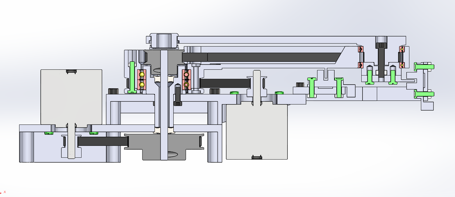
I have completed the easiest part for me which is the 3d design.
The software and development part will be harder.
I don’t know Klipper but there are good tutorials on Youtube.
I bought an SKR mini E3 V2 board and I have a Raspberrypi 2.
I started looking at your configuration files: in printer.cfg at the line [mcu pi] serial: /tmp/klipper_host_mcu what does this file contain?
Thank you

4 Likes


5 Likes

Hello @maxxou89

the software is the hardest part for me as well.
I dont know what “klipper_host_mcu” contains, it gets created or referenced when following the Instructions for setting up the pi as a secondary mcu (only needed when the pi GPIO is used for buttons or LED control)
See klipper/docs/RPi_microcontroller.md at master · Klipper3d/klipper · GitHub for that process.
It is not accessible for me with the normal pi user account.

As I am not an IT guy, I struggled a bit with the setup process and I made a short list of steps in case I had to to it again. Here it is, maybe it helps you:

  1. Flash Mainsail on sd card with Raspberry pi installer
    set WLAN settings & Login under settings

Insert SD card and let boot
use Putty or similar to connect - IP can be found in Router
Default login: user:pi password: raspberry
Search for & flollow instructions on how to flash the mcu connected to your pi

  1. Follow instructions to install rpi as secondary mcu to use RPI GPIO
    klipper/docs/RPi_microcontroller.md at master · Klipper3d/klipper · GitHub

for LED:
follw instructions to install:
GitHub - julianschill/moonshine: Controlling LEDs from Klipper using LED Control from jackw01. This repository contains the needed files and an installation script.
To edit file:
Install vim editor with ‘sudo apt install vim -y’
change to root user with ‘sudo su’
open file with ‘vim /etc/default/ledcontrol’
switch to instert mode by pressing ‘i’, edit LED number, exit insert mode by pressing ‘esc’
save with ‘:w’, leave with ‘:x’

  1. connect to the device with browser
    upload printer.cfg
    restart software

I had one small issue with the mechanic that you may also encounter:
If the central shaft is magnetic, the magnet will be attracted to the shaft, potentially causing some of these issues:

  • clicking noise when the arm snaps down to the shaft
  • loosing the ball if snapping down
  • sticking, if the magnet force is stronger than the motor torque

I eliminated that problem by mounting the shaft a few mm lower than originally designed.
You can see it when comparing the CAD pictures to the fotos of the real thing.

I like your choice of shorter Nema17 motors and the positioning of the endstop on the side.
The motors will be strong enough and allow for a compact design and the central arm should be stiff enough to reliably clear the endstop for the outer arm.

The Table looks interesing as well, did you make it or is it available to buy somewhere?

Thank you for your advice, it will help me to complete this project.
On the SKR card you can manage an LED strip with Klipper but apparently this is not a reliable solution?
Yes the magnet is very powerful and there is a risk of being attracted by the axis or metal screw.
protect with a non-magnetic material: copper foil? I’m going to do some tests.
The table comes from IKEA, it is the Borgeby model available in France.
I’m taking the bottom tray to make my sand table, I don’t know if it’s a good solution but I didn’t want to do any carpentry.
Sorry for the translation, I go through Google.


Capture d'écran_20221217_103801

3 Likes

I tried that when I started, using this plugin for led animations: GitHub - julianschill/klipper-led_effect: LED effects plugin for klipper
But it seems like the comands for LED and normal G-Code are not running in parallel and G-Code gets prioritised. The result for me was, that the first few LEDs in the chain could be adressed fairly normally, but the ones further down the chain did not get a reliable signal when G-Code was running. I suspect, the comand was interrupted whenever a new G-Code line was processed, so the LEDs towards the end of the chain only got updated when no drawing was running or when the time in between G-Code lines happend to be long enough…

Non-Magnetic materials will not help, they dont shield against a static magnetic field.
I know, i design the electromagnetic parts of electric motors for a living :wink:
You could attach a steel plate to the underside of the magnet to redirect the field.
My first try would be a steel or iron plate of roughly twice the diameter of the Magnet and 2-3mm thickness.

1 Like

Thanks, I’ll see if I’m using the RPI-driven leds or an Alexa-driven led strip.
Yes the metal part under the magnet is a good solution.

I have a small problem when I make a home, the motor shakes but does not turn.
the motor wiring on the board is not clear to me, 2B/1B and 2A/1A on the board corresponds to +B/-B and +A/-A on the motor?
the optical sensors do not light up, bad connection? 3.3v or 5v or Klipper config?


Check your wiring.
The motor phases seem wrong.
According to the Motor datasheet, your motors are wired ABAB on the 4-pole connector but it should be AABB. Swap either the two outer or the two inner pins with each other.
The polarity is not really important, that just defines the motor direction.

Check the endstop wires as well, the marking on the Wires you connected to VOUT looks more like GND to me. Although wire markings on the cheap optical endstops dont have to be right. check the markings on the PCB to be sure.

thank you, yes it should as you say BB-AA and the non-name sensors are well in 5v, i checked

check the jumper next to VOUT, looks like you have it configured for external power supply - move it one over.
I use the 5V pins from the TFT and E0-STOP connectors to power the Endstops. Cant remember why but there was probably a reason i didnt use VOUT :slight_smile:

Did you change the wiring since those pictures? Because from the pictures, it looks wrong. Swap the middle two pins.

Any AABB, BBAA will work. The consequence of wiring one coil backwards is the motor will drive the other way. The consequence of swapping the coils is it will drive the wrong way. If you wire them ABAB, then you will get nothing but stuttering.

I also don’t usually trust the colors. If you want to make sure two wires from a stepper are part of the same coil, you can disconnect it from the skr, short two motor wires, and (like magic), the motor will be (significantly) harder to spin. The first coil is AA, the second is BB.

I would not start with home, if you can avoid it. Just jog the machine first, and check your endstop state (M119 in Marlin) is correct before going to home.

1 Like

Thank you very much for your help, my machine is operational. :grinning:
I note that I have a difference in position between X turning and Y blocked, this is surely due to the dimensions of the toothed pulleys (machined > printed)
Either I try to put machined toothed pulleys everywhere, or I redo the printed wheels, to see.
The X axis it does not matter because we can compensate it with Rotation_distance in klipper, you just have to see the pulley printed on the Y axis, a small modification to make.

Hallo maxxou89

cooles Design der Mechanik, gefällt mir sehr gut.
Freue mich schon dein fertiges Projekt zu sehen.

servus
Klaus

So the Y-arm does not return to the same position after one full rotation of X? I am not sure if I understand you right here.
If the printed pulley on the Y axis has a different number of teeth than the machined pulley in the center, the Y will not be independent from X-movements.

Or the belt may just slip if there is no tention on it.

1 Like

thank you Klaus, your model is also very cool