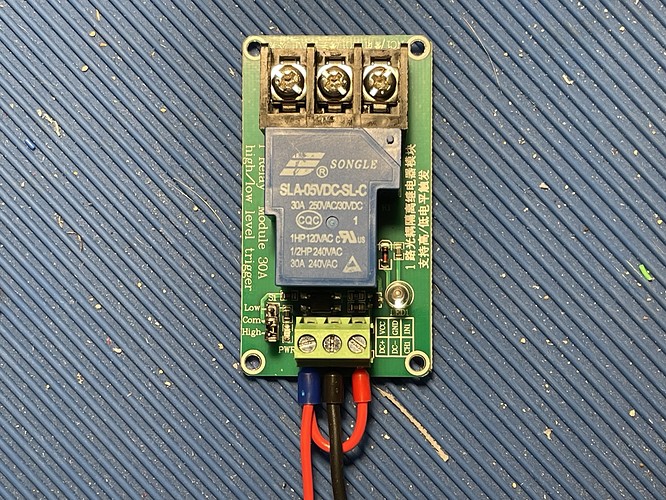
No need to start a new one really, but its up to you.
Okay.
It has a different wiring than the one I had planned to use so I don’t know where to connect it. If possible I’d prefer to still use HEAT2 on my SKR Pro so I don’t need to fuss with the firmware too much.
On the signal side, it has three inputs:
DC+ | VCC
DC- | GND
CH1 | IN1
If HEAT2 only has two posts (+/-) where do I send the signal from? Would I use HEAT2+ for VCC and HEAT2- for IN1 and then find a 12v ground?
I found several threads that answered it for the RAMBO boards but nothing clearly defined it for my SKR. I did see Jeffeb3’s suggestion to use this power strip, but I’m already running out of room in my control area.
It looks like the DC+ and DC- are for a steady 5V power supply to operate the relay since its optically isolated and other stuff. So you’ll need a steady 5V source to power it. The CH1 connection would be for the signal from the SKR board to activate the relay. Its also only 5V for the trigger line.
As far as where on the SKR board to get those connections, I can’t answer that. I’ve never used one of them.
It is absolutely your system and your choice, but I elected to have my eStop in the hot line of the AC feed into my “brain box” and ensure that it removes all power from everything. I didn’t want to have to worry about where power might still be going if there were an emergency. For me, the possibility of power going somewhere unwanted wouldn’t be worth the value of turning on that red light.
I read some more on the relay, and the DC+ and DC- are indeed for powering the optical side of the relay. The CH1 needs to be the same voltage as the DC+/-.
I also saw some sources say the DC side could be 5v-12v, but then others say it was 3.3v-5v. The fact that they also have a 12v version of this relay (SLA-12VDC-SL-C) leads me to believe the latter, but I decided to give it a try at the 12v I would get from HEAT2.
Since I only had 12+/- from HEAT2 I wondered if the relay could be energized the same time the signal was. So I did a test with a jumper wire going from the DC+ to the CH1 and connected DC+/- respectively. All of the tests were with no load on the AC side, but testing conductivity with my Fluke.
When I applied 12v the relay powered on and toggled the AC circuit immediately. I did some tests and it consistently opened/closed the circuit as expected, so I tried connecting it to HEAT2 on my SKR with my Fluke on COM/NO. Powering the spindle on the LCD immediately closed the AC circuit. Turning off power had a slight delay as the relay de-energized, but it was only half a second.
Here’s what it looks like now:
Is there anything wrong with this approach? It’s fully functional, but is there any longevity concerns with the relay given the 5v/12v disparity? It doesn’t feel like it is generating any noticeable heat (my garage is really hot today so hard to tell).
I’ll likely go ahead and get the 12v version regardless, but if it is reasonable to use as-is for short periods I can continue working on my wiring cleanup.
As far as using the + voltage to power it and give it the signal on CH1 at the same time, that’s perfectly fine.
As far as using 12v on a 5v relay, it’s anyone’s guess as to what will happen. It could last forever, or it could fail in 2 minutes. It’s not only dependant on the circuitry’s absolute maximum ratings, but also a small bit of luck as some parts are just more tolerable than others.
It’s best to pick up the correct kind asap, but in the mean time it’ll work until it doesn’t.
And if it does fail, it’ll likely just quit working, no fancy explosions.
Which, despite the misleading contextual clues, is a good thing… Well, unless you have both decent insurance and a YouTube channel…
I’m a glass-half-full person myself ![]()
House wiring in the US should never break the neutral. You always switch the hot on and off. If yours is opening the neutral it’s wrong as well as very unsafe.
