I just tried to do the z leveling on my LR 3 and had a difference of 1.68 (x- max was the furthest)…i then input m666 1.68 then m500 and realized i had the x axis at the x+ max position. Then i homed the z and the x+ z endstop homes and drops a little. I tried inputting M666 -1.68 and M500 to see if it would go back but no change. Is there a video somewhere showing how to do this correctly?
I restarted the entire process now i get a difference of 3.54 and i cant keep the x+ z endstop from lowering down after it homes.
Is there a way to put it back to the settings before i input anything to start over?
M666 Z0 will reset just that one setting. M502 will reset all settings to the default. M500 is still needed to save those settings post the next restart. You can see a print out of all your settings with M503. And M666 with nothing after it will print out your current setting on M666
Ok cool ill reset to default and try the process again. Just to make sure as an example…if the x- max shows 127.58 and x+ max shows 129.32 which is a difference if 1.74. I would leave it set at x- max then input M666 Z1.74 or M666 Z-1.74?
I can never remember which one is which. I would just try one and then the other. If you tried M666 Z10 (and then G28 Z) and M666 Z-10, it should be very obvious.
The other thing is, you can accidentally wire the motors in the wrong ports, and it works, as long as the endstops and motors match. So it is better to just test it to see which direction moves which motor, rather than trying to determine it analytically.
Gotcha. So if you have to adjust the side that went the furthest then after you home the z it will drop that side down to equal the other side to be parallel to the work area correct?
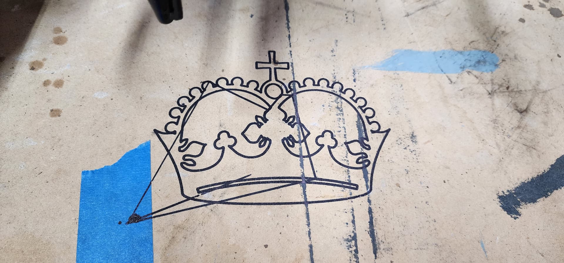
Ok so i got it within .1143mm with the z leveling so i gave the crown a shot. I followed all of the instructions. It drew the crown only the z bottomed out and could never lift the sharpie off the table. The instructions said to put the pen a hair above and it should start where i homed the head at which it did start where i had it in estlcam but the z did not start at the height i had it at.
Easy peasy. You are probably just missing the G92 at the top.
Try the premade one (it only takes a few minutes). Then try it again with your CAM. But this time, either add the G92 to the starting gcode, or reset the zero before starting.
I personally always set the zeroes myself. It is part of my startup rituals. I like to drive it around to the extremes and make sure things are set up right before I take a deep breath and hit start.
I just started cutting the strut plates out. I looked through that coordinates link you posted and tried to set the origin from the LCD with this info but it didnt work. Im cutting from the SD card so i went into the terminal on the LCD and put G92 X0 Y0 Z0 once i had the endmill in place. I dont have the option on my LCD to set home position. Is there a way to home the X and Y to where you want them then use the touch plate to set the Z height to the work piece? The thread says to use the touch plate and home the z…but the plate is ignored when you home the z so how would that work? Also is there a way to set up the gcode to get the x and y where you move the endmill to and automatically probe for the touch plate then start cutting?
"Using LCD
If you have an LCD with your controller, you can use the menus to move the tool to the origin that you want. Once there, select the “Set Home Position” in the menus.
I’m pretty new to this, so keep that in mind. This is the gcode I cobbled together and have on my SD card to probe and set my origin where I just probed:
M0 ATTACH PROBE ; Remind the user to attach the probe
G38.2 Z0 ; Home down for the touchplate
G92 Z0.5 ; Sets the offset for the touchplate, if the touchplate is 0.5mm thick
G0 Z5 F300 ; lifts the Z out of the way
G92 X0.000 Y0.000 Z5
M0 REMOVE PROBE; Remind the user to remove the probe
Edit: after looking at this, the two G92 lines could be consolidated into one.
So you have this gcode as a file on your SD card and run it first then run the file for what you are cutting? Or this is the start of all your cutting file gcodes?
It’s just on my SD card as a separate file that I run before starting the job (which is a separate file).
So I generally boot the machine, auto home all the axis, drive it to where I want to have my origin on the workpiece and execute that gcode. Then I find the cut file and run it.
the second G92 @Z5 is because the command before that drove the Z axis to 5mm to remove the probe. so it’s just retaining that location. It could be simplified to this:
M0 ATTACH PROBE ; Remind the user to attach the probe
G38.2 Z0 ; Home down for the touchplate
G92 X0.000 Y0.000 Z0.5 ; Sets the offset for the touchplate, if the touchplate is 0.5mm thick
G0 Z5 F300 ; lifts the Z out of the way
M0 REMOVE PROBE; Remind the user to remove the probe
And this sets the workpiece origin. So depending on the origin location you have designated in your cut file, this will treat the probe point as 0,0,0 and execute the job from there… if that makes sense.