Swapped in the new plate: (one good use of the extra height, maintenance)
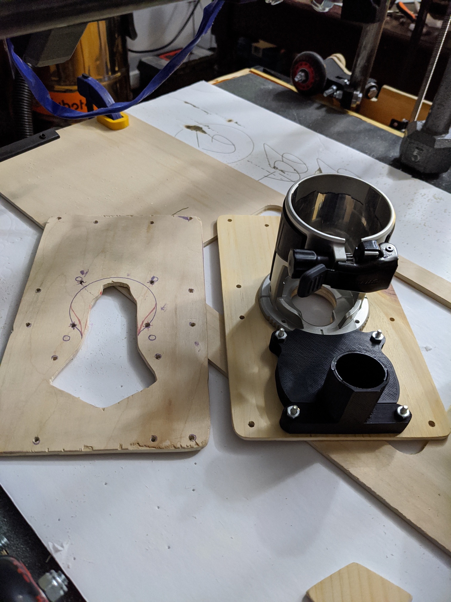
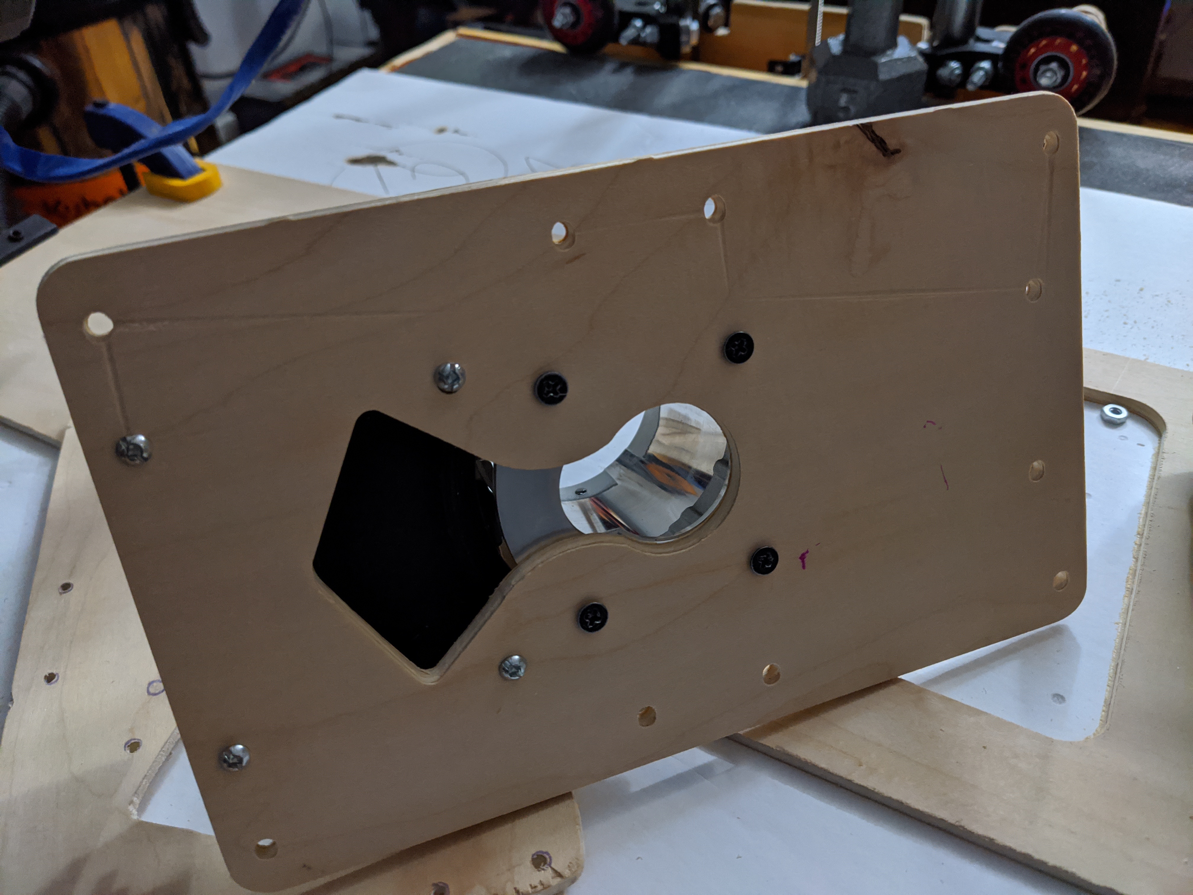
It turns out the holes I made have the router facing the way I had it originally, which avoids the V strip when opening it to add/remove the router.
Cheers!
Swapped in the new plate: (one good use of the extra height, maintenance)
It turns out the holes I made have the router facing the way I had it originally, which avoids the V strip when opening it to add/remove the router.
Cheers!
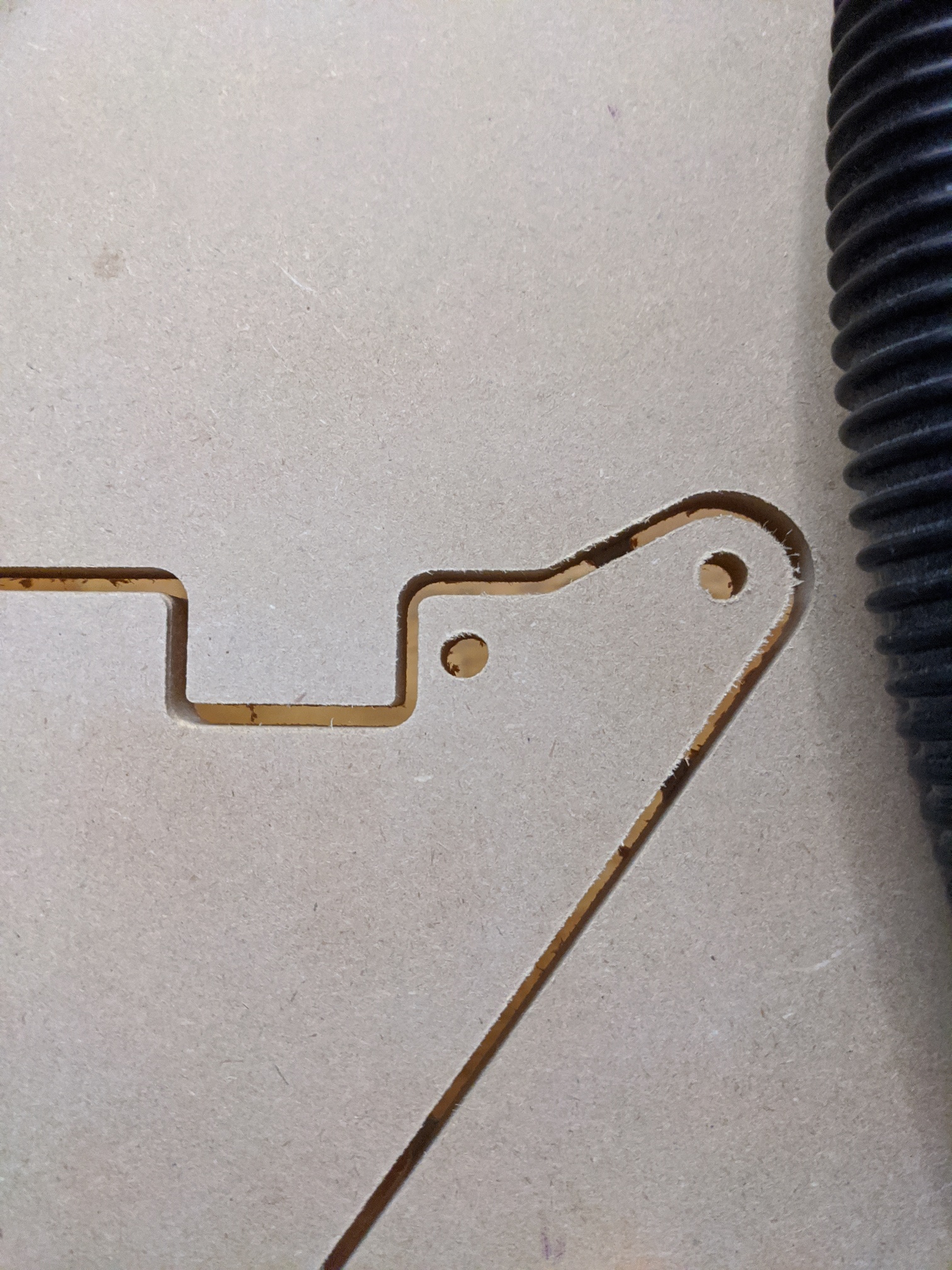
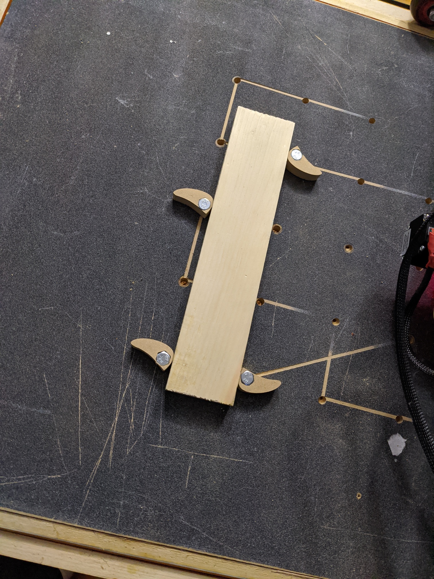
Did up some more flatware.
lowriderYY.gcode (604.1 KB)
Had to really push the length of the bit to get through the 13 mm wood, just using a 1/8th collet insert for now, have an extender on the way, which will likely solve that issue. Tried 2 mm high tabs, wasn’t enough to fight gravity, went with 4 mm and that was OK, but essentially got 2 mm results.
Cheers!
Created a bunch of new wooden washers, painted them black, added polyurethane to the y frames. Used FreeCAD for the first time, reminded me of why linux app get the rep they do. It works fine, but several youtube videos in -insert non English language- trying to figure out how to do exotic things like save files in dxf format, it’s a bit much. Oh it’s autocad dxf, not technical drawing dxf, oh, you don’t natively use dxf, even though you display the extension twice in the save dialog. Oh you can auto download support for dxf, yes and no hangs the system, two sessions of holding the power button down to recover later, I found the add in manager to let me install dxf support. lol Learned that it is hard to made a hole bigger on a small part, redid the cad slightly bigger, cut some more, good enough but too exact, had to file some room.
Cheers!
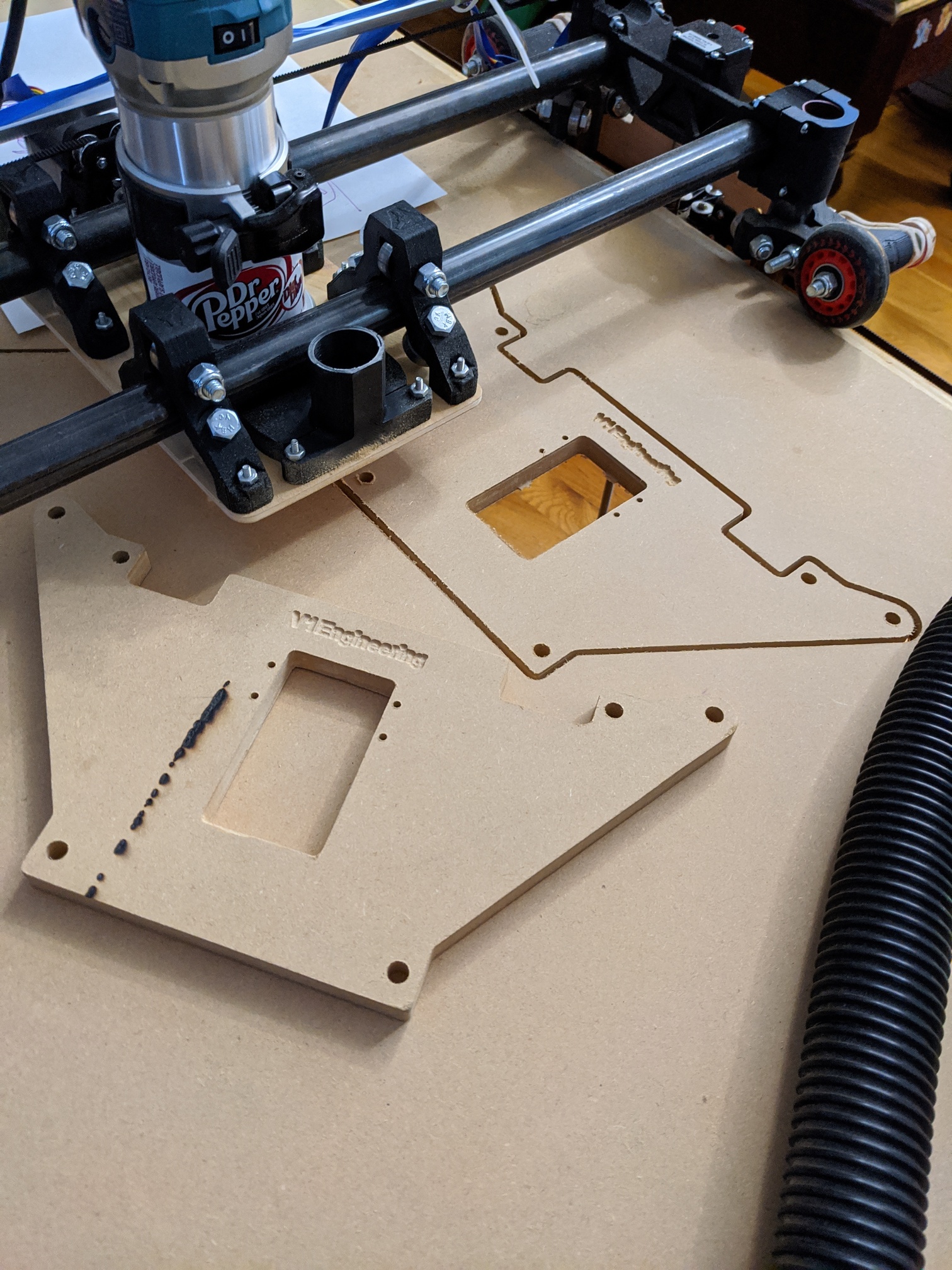
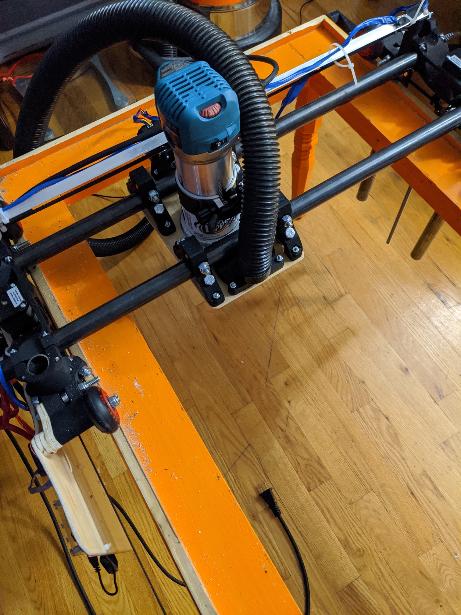
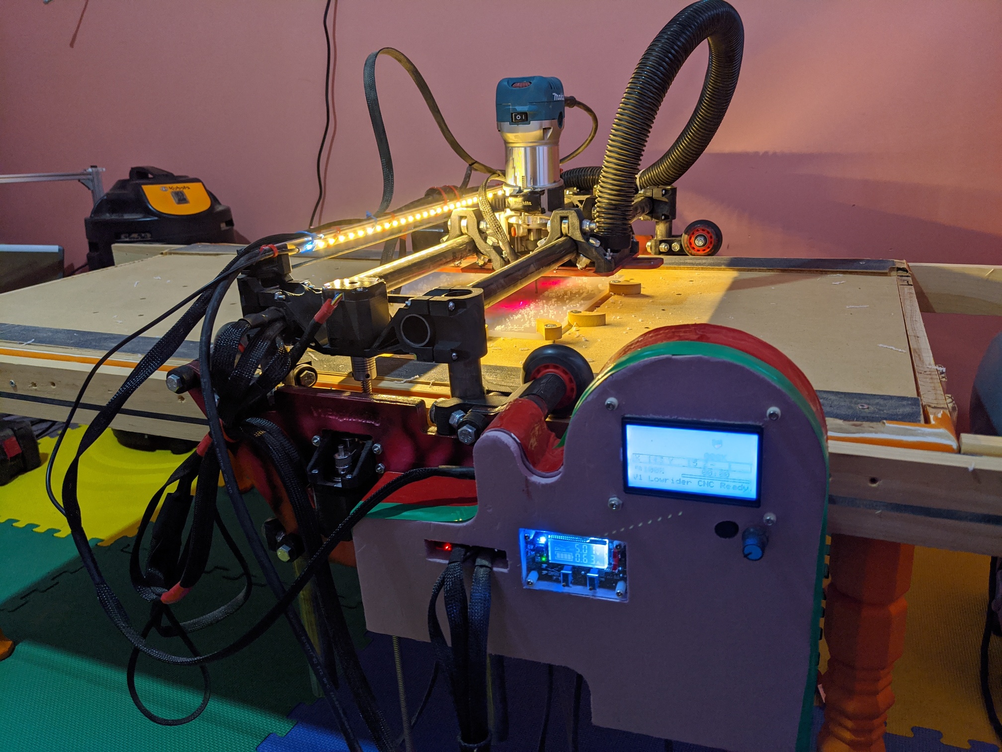
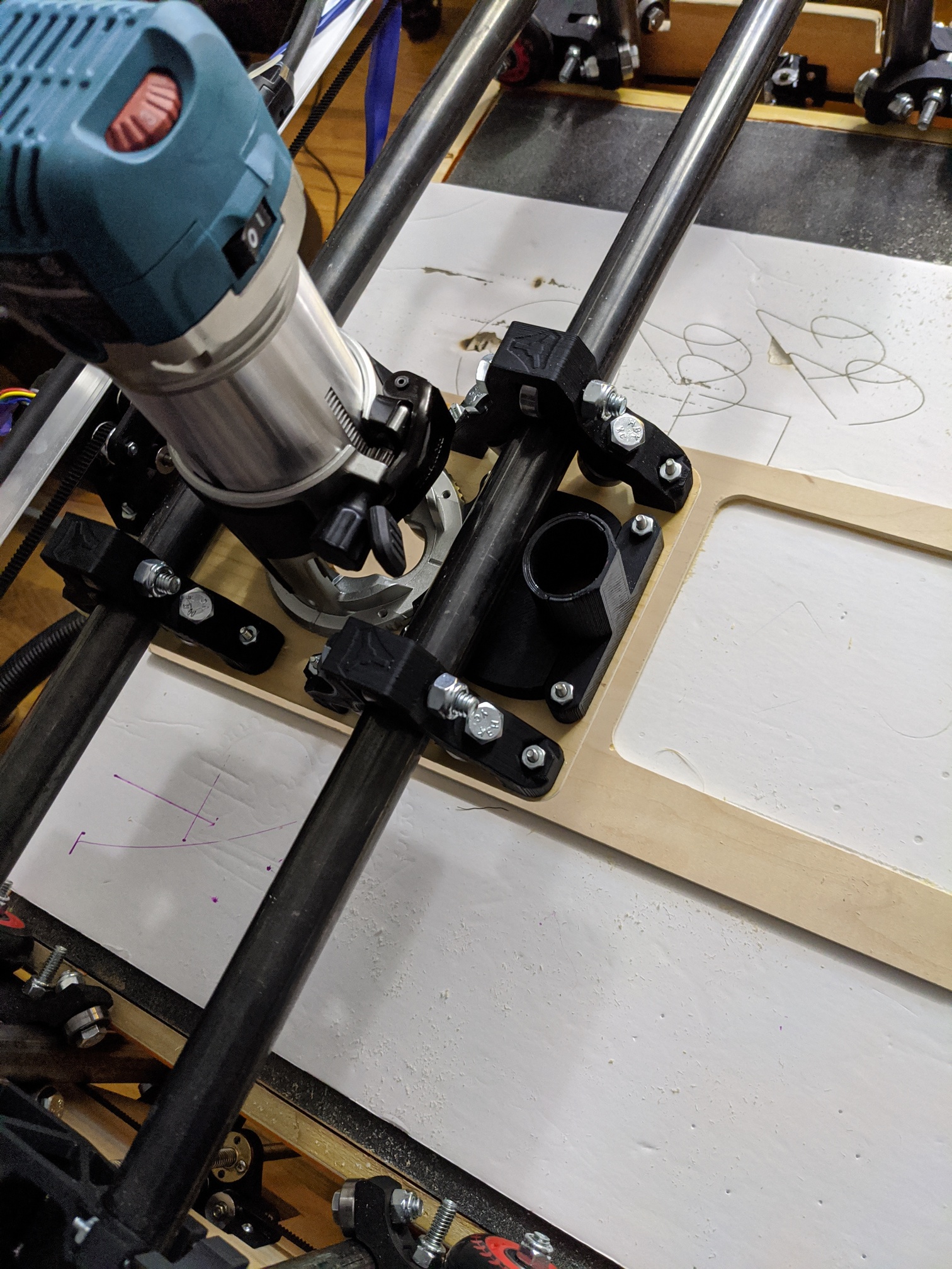
Installed the new side plates, you can’t see much but there is an air of something extra. I like it.
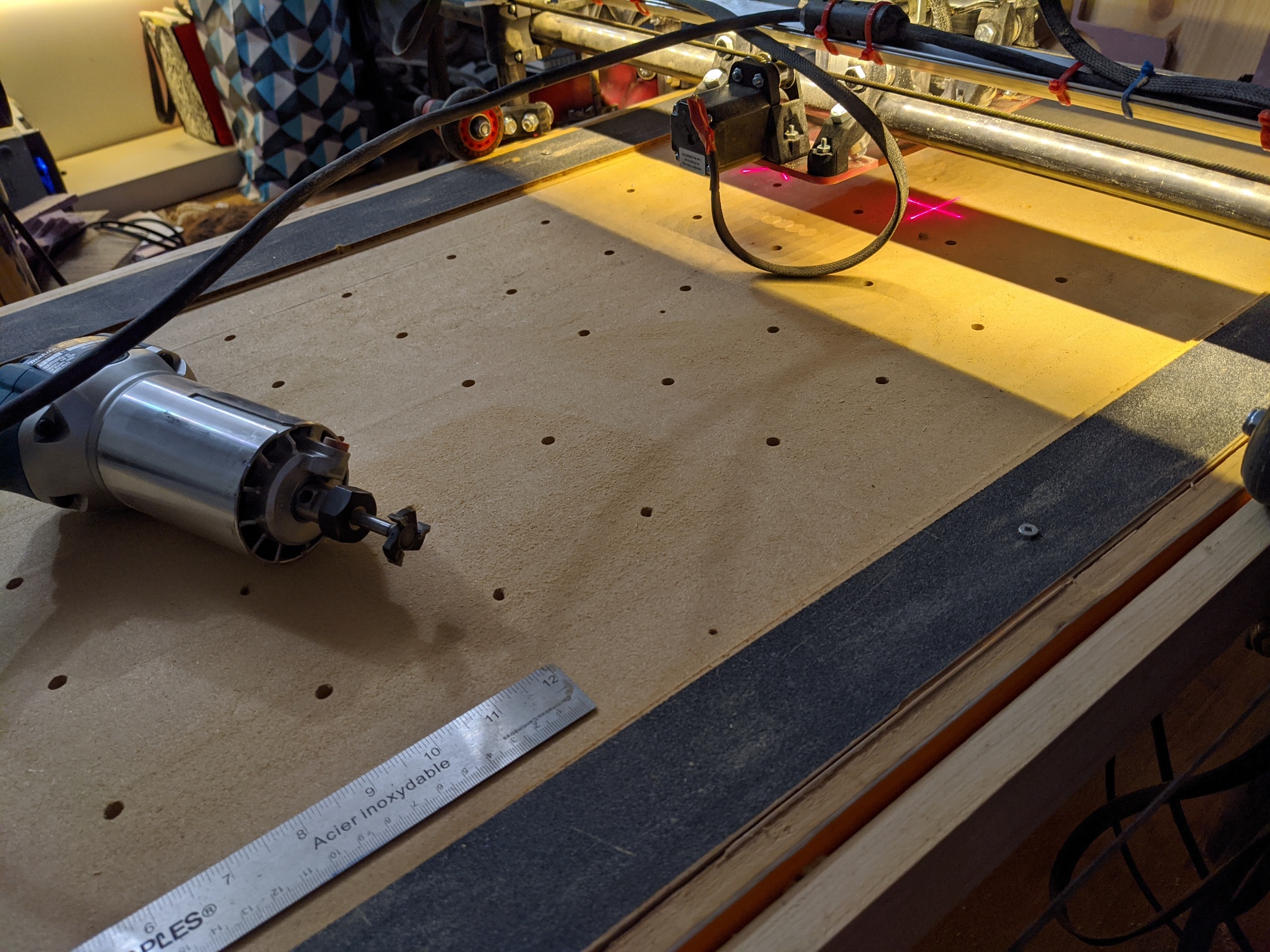
Current state of the machine:
I have the makita facing the side now Makitav2.gcode (26.6 KB) , that way I can more easily see the bit when lowering it and the power switch is in front of me. (I removed the label from the diet Dr. Pepper bottle top, leaving a clear window.)
I added some laser pointers for fun, may be helpful, but I didn’t dial anything in and the beam is 2mm or so, not very exact.
Added a square pocket to rest my pen holder, or could be useful for a laser.
I received my e-ink hat for the pi, some fun with that, I am not sure what to display on it, I have the V1 logo and thought about X, Y, and Z, but that would be better from the mini-rambo, and while I can hook up the e-ink to an arduino, but I don’t want to mess with firmware and chasing versions just yet.
Added some wood to the side to extend my reach in both XY directions, stacked foamular was too close for comfort. That messed with V guide with the extra X width, but I just fixed that with zip ties until I find more.
Oh, also bought more braid, went 100ft, slightly bigger width, not intentional.
Cheers!
Did up a mini-rambo cosy (954.8 KB FreeCAD file) . It’s crap quarter inch plywood, with three layers of 15 mm foam stuck together with dollar store crazy glue and electrical tape to form a 45mm tall shell (5 mm thick), with a snug fit lid. I like flex of the walls and can’t complain about the fit, that worked out well, still getting nonsense with trying to cut 15mm foam with a 15mm long bit, either it’s not deep enough or it’s shallow and deep, or I catch something along the way or the shop vac decides to suck it all in. 
Using 80mm spacing so it’s easy to clamp some typical wood sizes locally. Hole sizes match the lowrider 2 sized bolts, they just screw in directly.
Cheers!
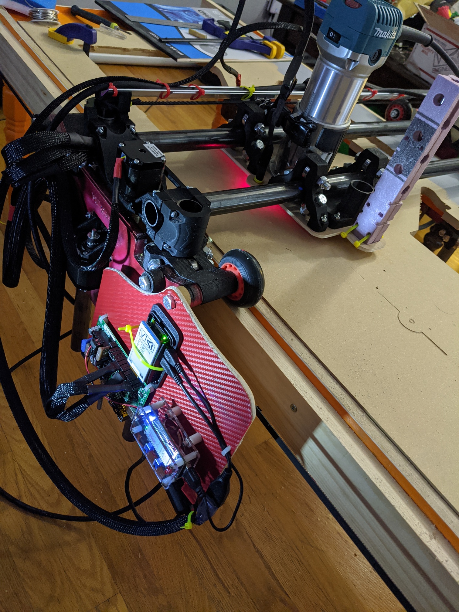
I added an lcd strip to the Al V, (running from the Brok buck converter, it’s constant current so if that’s an option dial up the current to run the pi as well.) rotated the pi 90 degrees and added a foam wedge to point the camera at the router, (Octoprint’s timelapse is kinda crappy though.) I surfaced the table, hopefully next cut won’t be so all over the place. (Octolapse is a well evolved bit of kit, useless to me though as there is no cnc profile or slicer settings.)
Jogging tips for surfacing:
EDIT: Oh, change the bag in your shop vac.
Cheers!
5mm with that bit is pretty big bite. Looks like it worked well though.
Nah, I went down until I was cutting a line from end to end, then I messed up and had to fix the other line to match and so on until I figured out what I was doing. When Octoprint crashes and then turns off the motors on reconnect it looked like the same height but it wasn’t, off by 1mm.
Cheers!
I think it even resets the microcontroller on connect.
Yes, I believe so.
Here is me, adding more pictures to the thread, so people in far off places can’t view it due to bandwidth and crappy browsers.
Relocated to the pink room, cutting plastic:
On cutting plastic, or rather this, it is freaking hard to cut by hand, make your tabs 0.5 mm high, make sure your holes go all the way through, if not, make another pass until it does. Cutting disks are useless, razors, drill bits, do nothing. No, you cannot fix it up later.
Cheers!
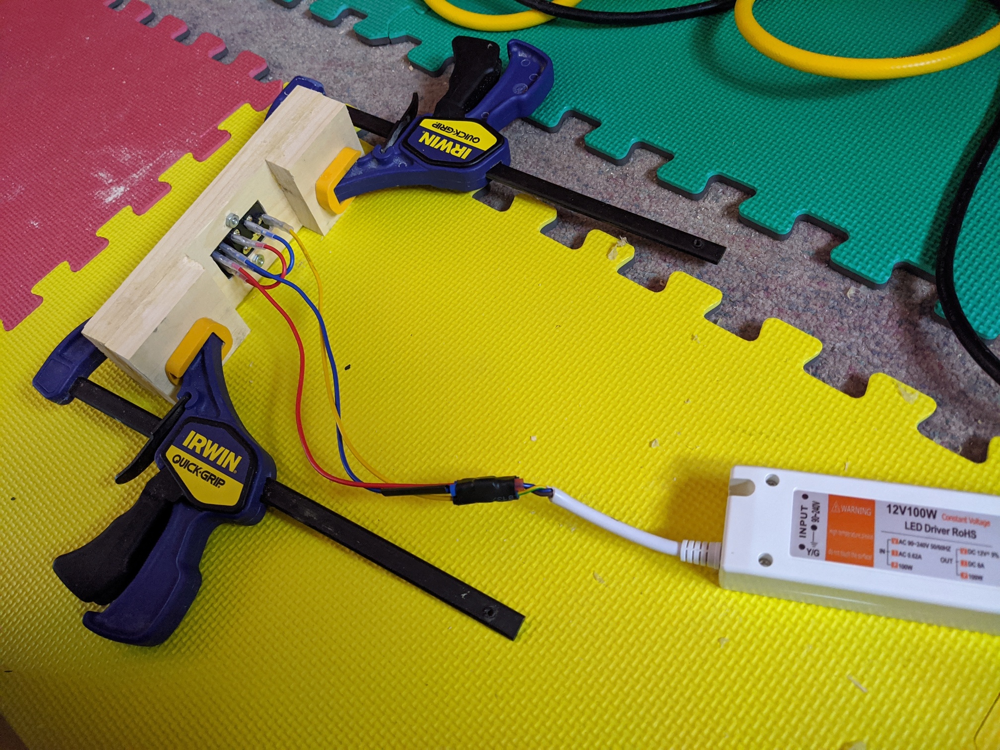
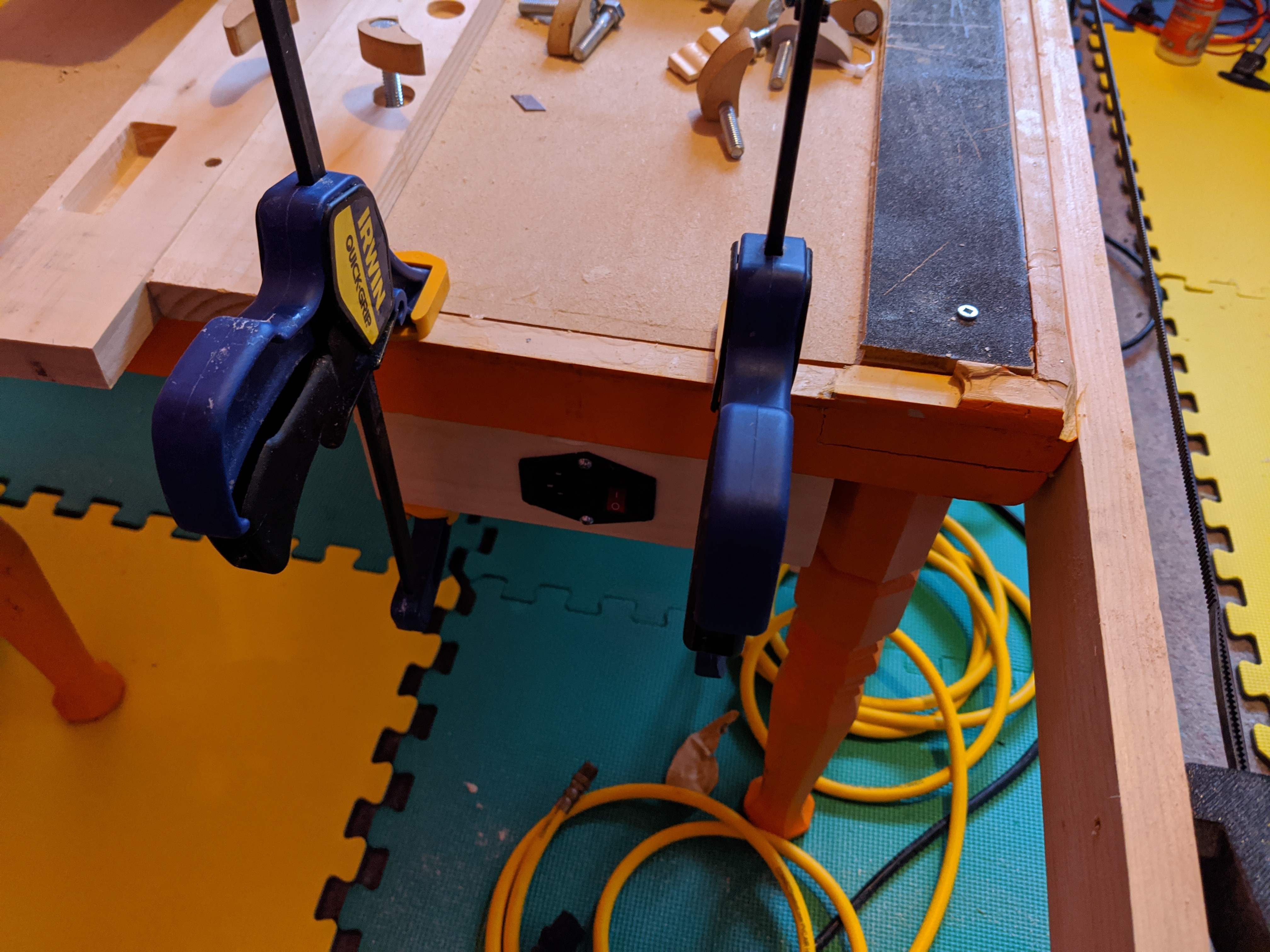
Replaced the power switch, using thicker wood, put it on the far side, using crimp connectors this time.
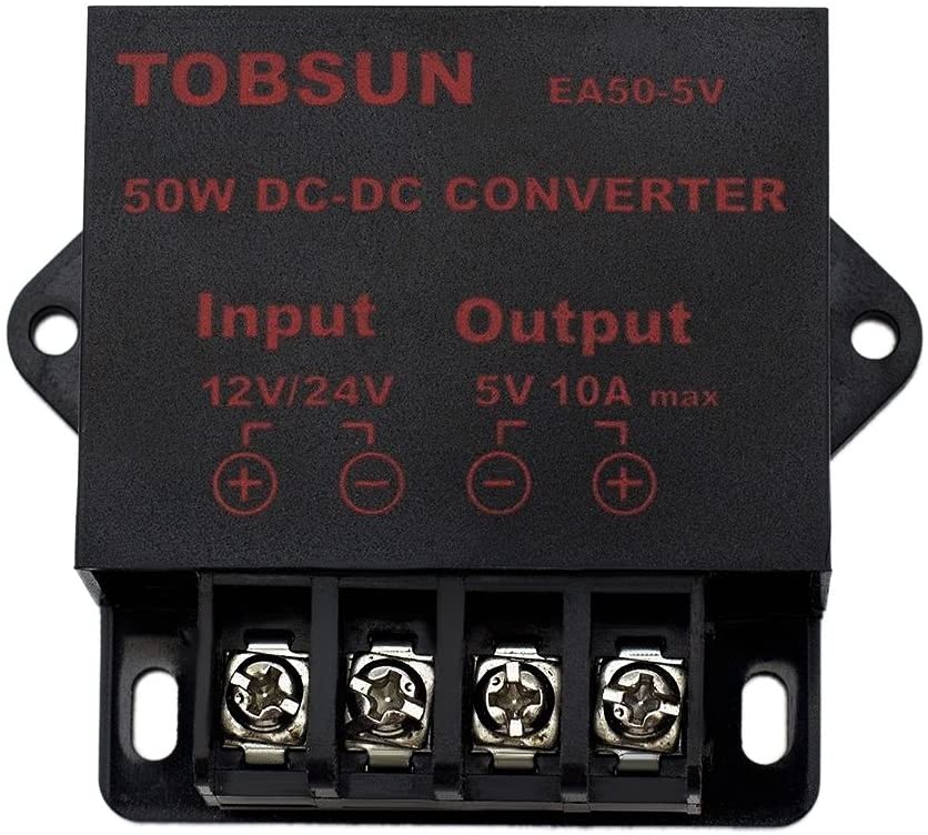
Using this buck converter instead of the one with the display:
Able to run the light strip and the laser pointers, as well the pi, without any current (electricity) issues.
Tried to use my previous display version buck converter with 12V, rather bad fail, thought I had fried the mini rambo. Ran through the fuses and they were fine, it just started working again. The interface for setting voltage and current is rather James Bond, if you turn the tiny screw 20 times in a row in a certain direction it will detect you and then start responding, PITA, and yes that is the setup, no exaggeration, the thing has to be under load to set the current max.
Cheers!
Bah! I went to buy one for my printer, and it is from Canada. You guys must get that all the time. I have a sympathy for you. Thanks for sharing.