Excited to see what you come up with for a table.
2 Likes
Yep, me too. Excited to see what you come up with for your table.
1 Like
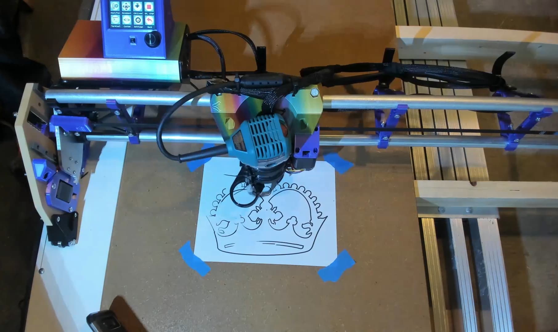
Janksy’s 1st crown attempt!
Am pleased considering the shortcuts I took… Paper was taped to decrepit damp swollen bent loosely laid chip spoilboard, resting on cambered 2x4s. Pen was loose (recommend 3 zip ties), neat idea to mount pen to vac holder. Still need to do Initial Squaring and level/tram with a surface bit. Core rail tensioners are loose, etc…
Again, love and appreciate the design. I keep discovering, realizing and appreciating details, e.g. like how the X Belt Tensioner profile/design’s tight tolerance allows barely sliding behind the Core. Cool engineering!
Short clip (~27s) @ LowRider V3 CNC build — Janksy's 1st crown - YouTube
Janksy currently rides on not a table legless flat surface. Copied and tweaked some forum ideas:
- Threw together some 10’ 2x4’s for the ~9’ x ~5’ frame, fastened with headlok 4-1/2", 16" on center.
- Left top open, no torsion skin, at least until solid base/legs are built, at which point Janksy can self surface/tram.
- Used 10’ 1"x 6" (actual size… 3/4" x 5.5") primed finger joint pine for Y rails. Would have used Melamine if could easily source long enough material.
- Let Y axis run past front end of the table to enable easier bit change access. Plus saved some cuts and the kit’s belt was just long enough to reach.
No legs, probably getting short term casters. Still figuring out how to hoist onto side against the wall when not in use.
Next steps:
- Figure out vertical storage, need functional parking bay.
- Surface top, calibrate, make some struts. Seal and pretty up.
- Ramping up on Paulk, and similar builders/makers ideas for worktop/workshop stuff.
Cheers!
6 Likes
've had worse ideas, thinking Harbor Fright’s $15 rope and tackle usually used to hang your meat, is worth trying out on my LowRider not a table surface.
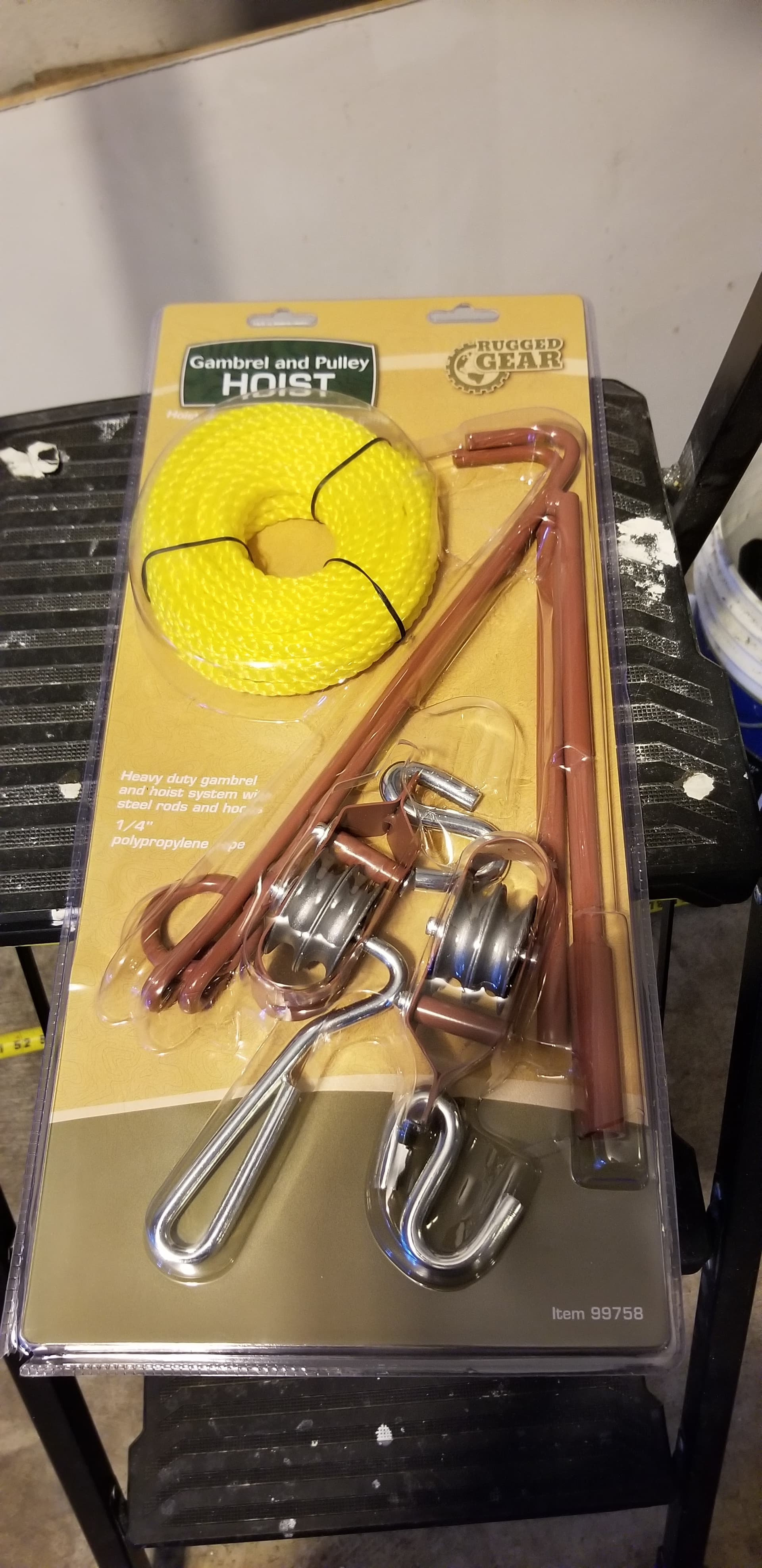
Suspending using E-Track to split load across multiple joists, and provide options later for easy overhead vac/power.
Really like super strut, but don’t like how a complete system prices out to. So, doing best I can by frequently asking myself WWMD? (What would Macgyver do).
1 Like
Created a video… Hope this helps folks figuring out whether, and how to build their LowRider 3!
Feedback appreciated, cheers!

Went a bit nuts on the indexing. My thinking is that this approach helps make info more discoverable.
00:00 - Intro and video goals
00:48 - WHAT’s a LowRider CNC for? Answer: Subtractive Manufacturing
01:30 - WHY build a LowRider? Answer: Step up from my baby CNC, right balance of quality and price for me.
02:20 - MPCNC is good, but I want a LowRider 3
02:43 - Pick your own size, or sizes even…
04:51 - Using Controller+TFT case by V1E Community member Doug Joseph
04:55 - Hassle free kits and parts available from https://shop.v1engineering.com, Controllers come with software preloaded.
05:48 - Parts printed, milled and delivered
06:24 - Unboxing V1E LowRider 3 Kit. Woot!
06:28 - Assemble LR3 Core
06:36 - Ream holes, reverse drill helps screws slip in tight
06:54 - Assemble X Drive
07:12 - Mount X Drive
07:15 - Stare at your Core for a bit, it’s so pretty
07:16 - Mount X endstop to Core
07:25 - Assemble Y Steppers
07:51 - Soldered Z endstops, too tight for spade connectors
07:56 - XZ Lead screw stubs. Reverse drill with 13/32 bit
08:02 - Assemble XZ plates
08:24 - Marry XZ to YZ plates
08:34 - Marry XZ to YZ plate rails
08:45 - Mount Z drive to YZ plate
08:55 - Wiring Z endstops, solder
09:03 - Wiring Z endstops, test
09:08 - Assemble Z endstops
09:16 - Mount Z endstops
09:18 - Adjust XZ plate, was binding
09:26 - Mount Z endstops
09:31 - Mount Y Drive
09:42 - Wiring Y endstop, solder
09:50 - Mount Y endstop, wiring routing
09:55 - Wiring routing
09:57 - Mount Y endstop, wiring routing
10:00 - Assemble wheels
10:05 - Mount wheels to YZ plate
10:10 - Assemble and mount Rail Rollers
10:19 - Assemble Beam, strut order… 1) Front, 2) Bottom, 3) Back
10:21 - mount braces
10:25 - LR3 Calculator, pipe and table size
10:28 - Front, loosely insert screws
10:36 - Bottom, loosely insert screws
10:41 - Rear, loosely insert screws
10:51 - Front, check straight, snug clamps
10:58 - Mount core
11:00 - Mount YZ plate
11:10 - Assemble X Belt
11:10 - Insert X Belt
11:12 - Mount X Belt holder
11:15 - Check X Belt end not blocking Z axis motion
11:17 - Mount X belt tensioner
11:28 - Fix for if X Belt stub is too loose
11:31 - Attach PETG tool mount
11:38 - Attach Vac hose mount
11:40 - Wiring SKR Pro 1.2 Controller
11:40 - Bend/clip diag driver pin
11:45 - Change jumpers
11:48 - Mount drivers
11:54 - Remove JST shields
12:03 - TMC2209 driver pinouts
12:05 - Wiring 〉 Route and Sleeve (1/2" wrap)
12:05 - Left YZ sleeve
12:15 - Routing right YZ
12:24 - Extend right YZ, use solder butt connectors
12:54 - Right YZ, 1/2" sleeve wrap
12:59 - NOT using cable gland, case holes too small
13:05 - Extend wires for X axis
13:16 - Wire X axis, test endstop
13:23 - Wire X axis routing and 1/2" sleeve
13:46 - X axis, verify range of motion. Router cord blockage
14:06 - Wire X axis, cable management
14:20 - Case wiring, routing power
14:42 - Controller wiring, driver endstops
15:03 - Wiring controller, fans and TFT
15:37 - Build minimum viable Sled. Use LR3 Sled edition to finish LR3!
17:12 - Motion test, FAIL - Y stepper wiring reversed
17:21 - Motion test, SUCCESS - Homed and move as expected
17:28 - Crown Test, SUCCESS, kinda…
17:47 - Struts 〉 Initial squaring
17:48 - Attach pen to Core
17:50 - Generate test gcode
17:51 - Connect via Repetier
17:53 - FAIL, relative positioning was set ![]()
17:54 - Typed gcode for corner moves
18:02 - Measure squareness
18:05 - Config homing offsets M666
18:07 - Z Leveling
18:19 - Struts 〉 Design
Calc size, download files
Use OpenScad & Estlcam to prepare gcode
18:31 - Struts 〉 First cut ~56mins
18:31 - Fasten spoilboard and stock
18:40 - Cut first strut
18:47 - Post cleanup, too long
18:54 - Struts 〉 Second cut ~42mins
19:02 - Post cleanup, Remove/trim debris, sand, vac
19:09 - Paint it black
19:16 - Surfacing Spoilboard
19:16 - Create toolpath
19:17 - Cut ~0.5mm in ~61mins
19:25 - Struts 〉 Make custom front strut
19:25 - OpenScad 〉 Customize, export .SVG
19:26 - Estlcam 〉 Create and Preview toolpaths
19:28 - Repetier 〉 Load .gcode
19:28 - Carve and cut 42mins
19:35 - Struts 〉 Paint 〉 2nd coat, protect via Shellac/Polycrylic
19:37 - Final Assembly - Mount struts to beam
19:40 - Temporarily disassemble beam
19:57 - Mount bottom strut
20:02 - Mount front strut
20:07 - Mount YZ plates and rear strut
20:17 - Wrap up
Future upgrades - Table, Vac, drag chain and more…
Check out https://forum.v1engineering.com
Thank you! Want to see more?
13 Likes
Some Endstop wiring length info for my build, with 49-1/2" (1257mm) usable cutting width.
Sharing details since I asked during my build, and @KL2001 asked similar question today.
Didn’t have this info for my build, and extended endstop wires by soldering butt connectors (fast video clip, don’t blink!). Used a mix of 3x extension wiring kits from V1E Shop and some 22AWG wiring I happened to have.
Knowing what I know now, would’ve cut the following endstop wiring lengths upfront during initial build to help save some splicing/soldering time.
| End stop | Length to Controller Box | Total (includes 400mm for 2x Box length) |
|---|---|---|
| X/touchplate | 1900mm | 2300mm |
| Y1 | 550mm | 950mm |
| Z1 | 700mm | 1100mm |
| Y2 | 2000mm | 2400mm |
| Z2 | 2000mm | 2400mm |
- Some context/thinking behind the generous lengths mentioned above :
- Middle column lengths are distance to closest opening on the beam mounted controller box. I used Doug Joseph’s case. Y1/Z1 enter different Box hole than X/touchplate/Y2/Z2.
- 400mm is 2x Box length, that’s more than plenty to route within the box, expect to cut excess and throw into your misc wiring cutoff’s container. Optimized for my time over minimizing waste.
- Included extra for Y/Z endstop wiring incase I modify YZ plates to be 100mm taller for larger Z cut capacity.
- Included extra for X endstop (and touchplate) wiring to make wide turn within drag chain (or tape measure).
- Used 22AWG, soldered and heatshrinked all endstops. However, for the Y endstop, wish I’d instead used decent tight spade connectors (from an autostore). The Y endstops stick out and are fragile, they’re likely to break if/when LowRider is being frequently stored/relocated.
- Ideally, some less fragile endstops for Y axis would be nice, as a future upgrade, any recommendations? Still need alternative endstop sensor to be accurate, reliable and relatively cheap.
Think @stevempotter uses hall effect based sensors on their MPCNC? - That said, I personally recommend using the documented endstops to begin with, you don’t want to introduce more variables and increase initial build frustration. Best to initially focus on getting to a good working state using stock parts. Upgrade later, LR3 will probably be a ongoing project after all…
- Ideally, some less fragile endstops for Y axis would be nice, as a future upgrade, any recommendations? Still need alternative endstop sensor to be accurate, reliable and relatively cheap.
5 Likes
Yes, I have one Hall effect switch for each stepper motor (or, 2 for each of the X and Y axes, and one for the Z-up) and I have to say that after a year of using the machine, they work very reliably. You don’t have to worry about bumping them, or any effects of dust. Here is a video about them: https://youtu.be/ztcMPmEYCmw?t=763
I carefully measured their repeatability and it came out to about 15 microns. The standard microswitches actually came out a bit better, about 10um. (standard deviation of many measurements using a digital micrometer to trigger them.)
2 Likes
Created separate topic with details about my LR3’s front grill

4 Likes
“True Level” will have to remain a fantasy, for now.
Have procrastinated, overly deliberated and navel gazed on the ideal ‘medium sized work’ workbench. Am just going to quickly throw something together, will look something like below, with casters. I can always add levels and lasers later…
Sizing surface for cutting 2’x4’ stock. Clear front makes this a usable regular bench. Will overhang top surface enough to enable clamping various things. Finished surface will be 36" high, with adjustments to account for floor level and earth’s curvature. Standardizing on 36" height for misc tool stands.
2 Likes
Me: Progress! Today, I’ve decided how wide to make my mostly LR3 workbench.
A few minutes later…
ColinFurze: Progress! Today, I’ve finished initial build out of the ultimate DREAM workshop, and dropped a kick-arse YouTube video…

Me: ![]() Wow! Time for me to listen to Amazon.com again…
Wow! Time for me to listen to Amazon.com again…
3 Likes
Yeah. Colin Furze has no fear and so much talent.
3 Likes
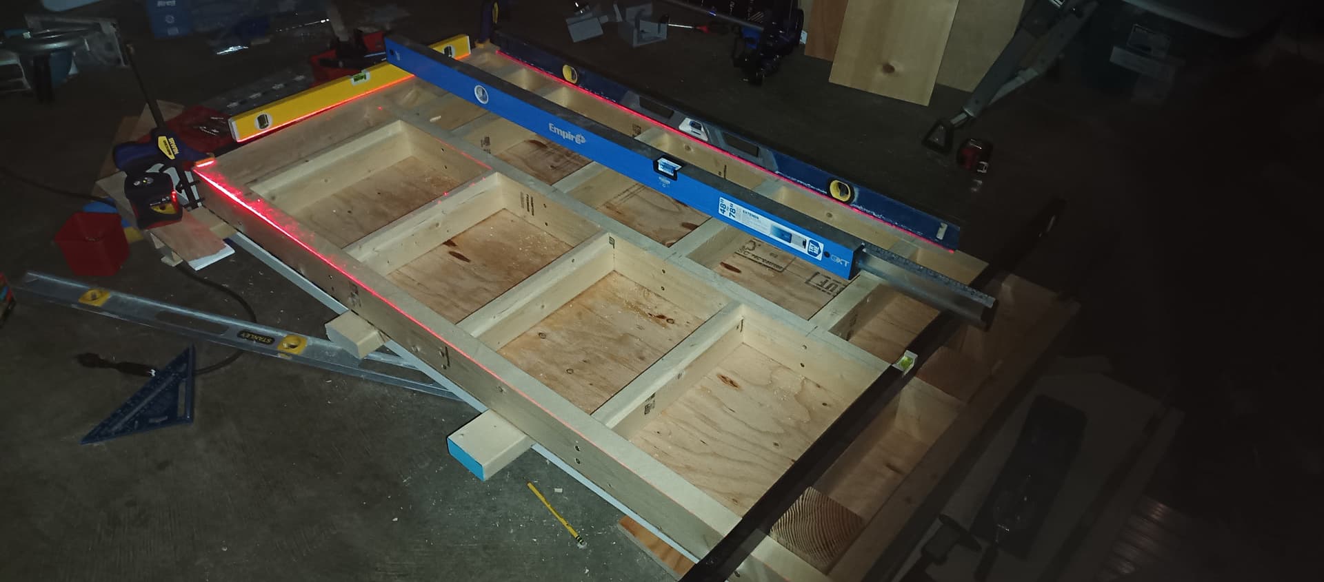
Anyone recommend sealing/painting the inside of their torsion box?
My mostly LR3 workbench, topped with a partial torsion box, is in an unconditioned garage, so dry, but enduring the Pacific Northwest climate.
The “torsion box” isn’t fully boxed, will be eventually leaving off front rail/apron so some plastic containers can slide in. Front rail is just temporarily fastened while I get rest of blocking and top/bottom skins fastened.
2 Likes
Sending an update to 1) get feedback on my mistakes, 2) share ideas that might help others, 3) help motivate me to get this done,
This is relatively simple build. No fancy collapsing/rotating mechanisms. Assembling using easy to modify in the future screws, except for the box which also has glue. My goal is to build enough so LR3 is always setup to use. But build in a way that enables some probable upgrades to be easily added.
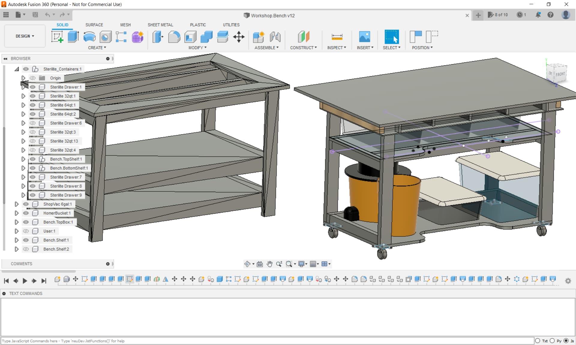
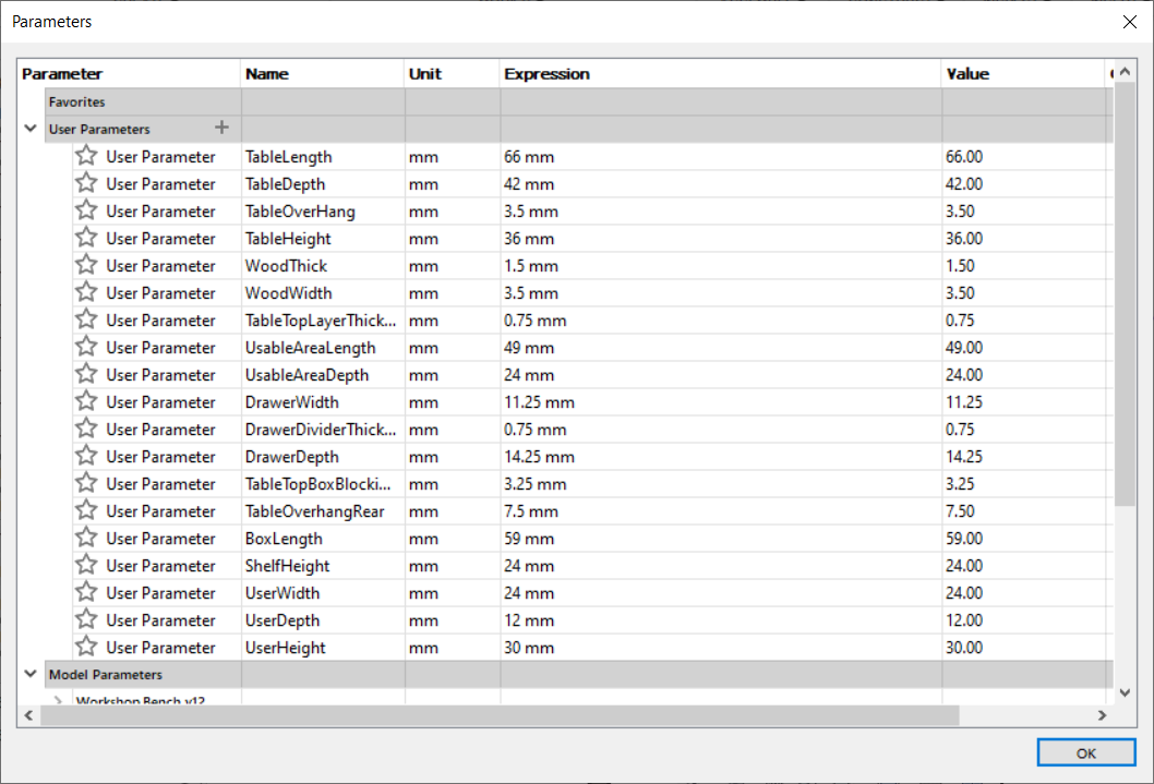
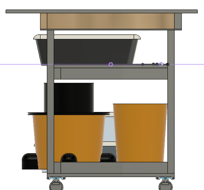
Tried modeling in OpenSCAD, but ended up abandoning/pausing that design. Instead, have created a somewhat parametric design using Fusion 360. My LR3 will sit perpendicular to most folks’ builds (see earlier post), front will be clear, and shelves will be recessed/contoured to allow usage as a regular assembly workbench. Still figuring out vice type and location.
.
Managed to squeeze some Sterilite containers into the almost a torsion box top, can alternatively insert 12x1 plank and use as a desk extension. Did this by ripping the 2x4 blocking to double up as drawer/shelf runners…
.
Baby got back! Decided to extend rear to ensure LR3 doesn’t overhang, controller box and vac hose stick out a bit. This’ll reduce risk of damage, and make future enclosing of the LR3 easier (dust/noise control):
Beyond this sketch, will be adding additional ply sheets on the sides, maybe the back too, to hang/mount stock/stuff, and add shear strength/rigidity. Adding diagonal bracing as needed (steel cables maybe like Stuff Made Here’s sweet puzzle solving CNC).

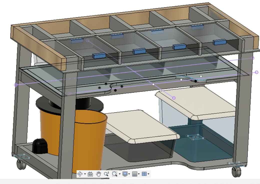
Legs will insert into openings within underside of the torsion box, will add brackets and bolts to allow tuning corners to be on the same plane. Simple 3"-4" braking-casters for now, can get fancy if/when needed later on.
Dimensioned lower section to fit in 28" opening, so can move/transport in/out house through 30"+ door entry. Outdoor weather’s crap right now. Top will be removable for transport and/or ‘portable’ to jobsite/friends.
Will be running vac, with dust stop collector, similar to bench in LR3 docs. I didn’t bother to sketch, power/controller cords and E-Stop, they’ll be strapped on at the end. Am copying JeffeB (and others) by having a 1-1/2" thick table top (with spoilboard) with plenty of overhang, and plenty strong to enable mounting power/controller enclosures.
3 Likes
For me, real life is nothing like those many, many, workbench YouTube videos with their slick build montages.
Making progress to somewhere…
Drop table and overhang cuts would be nice. Best I can think of currently is to have the Y rails, on bench dog fastened rails. Or, build yet another LR3 table, a drop table version. The LR3 is portable after all. Want to start another build project before I’ve finished the current project…
4 Likes
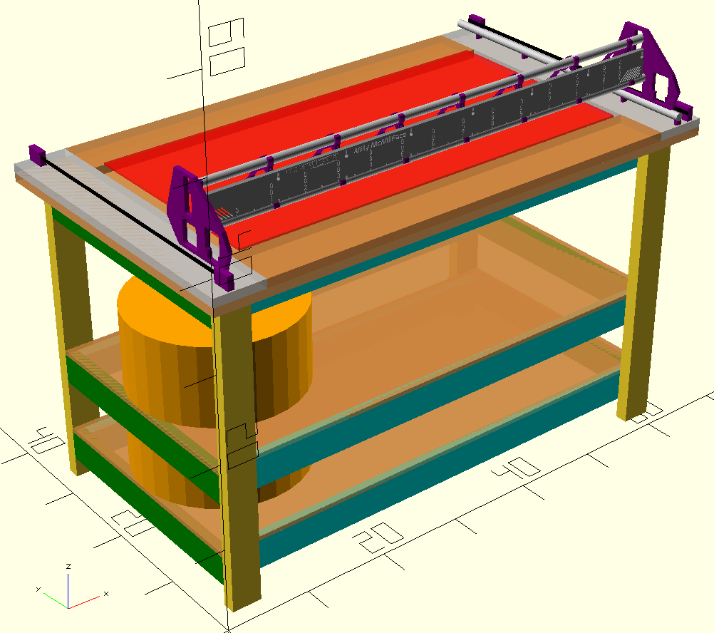
hhhmmmm… I’m no table expert but I think it’s upside-down …
It’s a drop table. Aaron probably dropped it.
Umm… Wasn’t intending to make a dropped drop table. Original plan was…

That, plus some bracing, with an adjustable/removable top torsion.
Was wanting to figure out a way to enable LR to occasionally overhang the front to cut vertical/thicker stock.
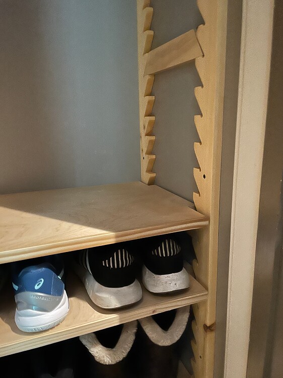
However… these dropped drop table mentions are sparking ideas about adding adjustable height shelf (using pins, peg holes, or something like Josh’s shoe rack, or something else?). LR3 would ride ply boxes that slot and lock onto what looks like upside down table legs at first glance.
Any additional adjustable height shelf ideas? Must involve ply/lumber/emt or something else cheap and easy to find at homedepot/lowes. e.g. doubled peg board? Trying to avoid expensive materials.
Resisting scope creep, and getting on with initial plan. Additionally implementing drop table feature will be good to add later.
2 Likes
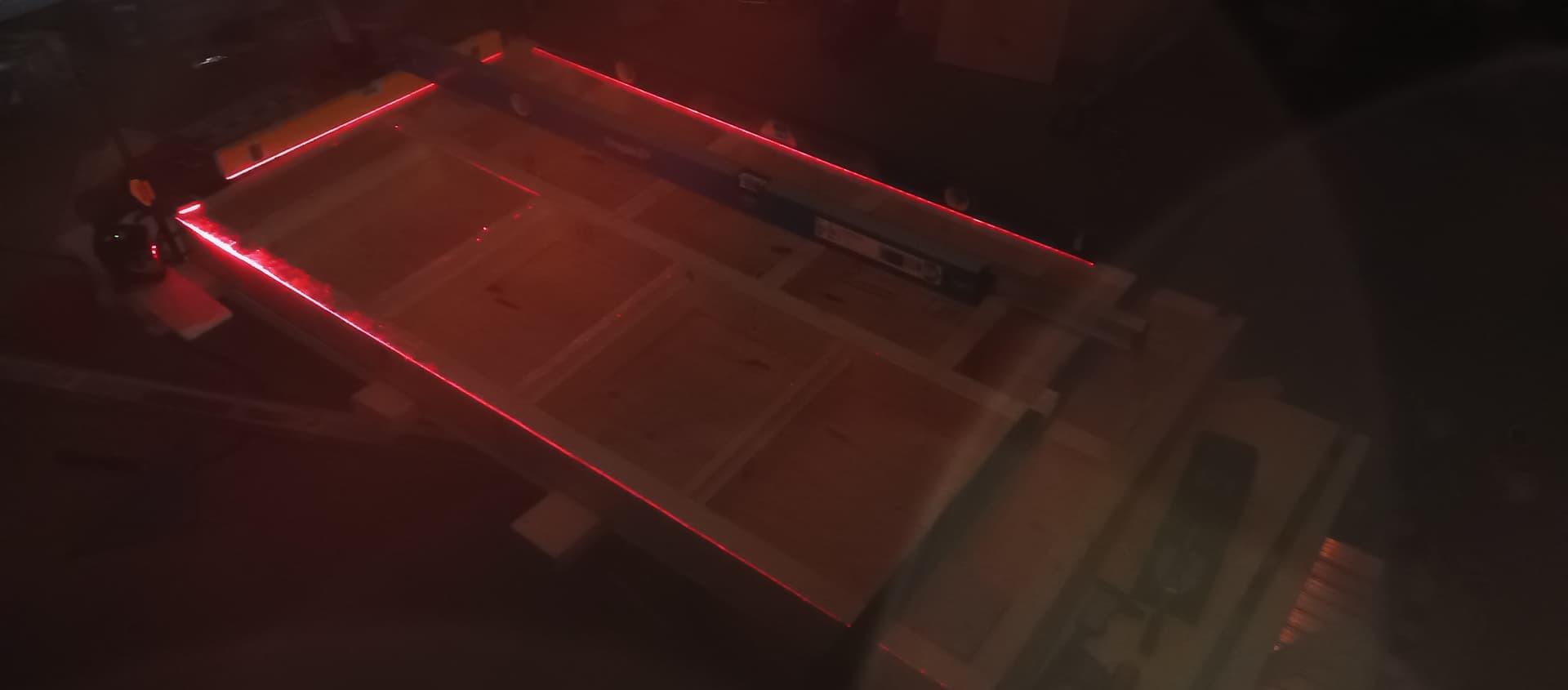
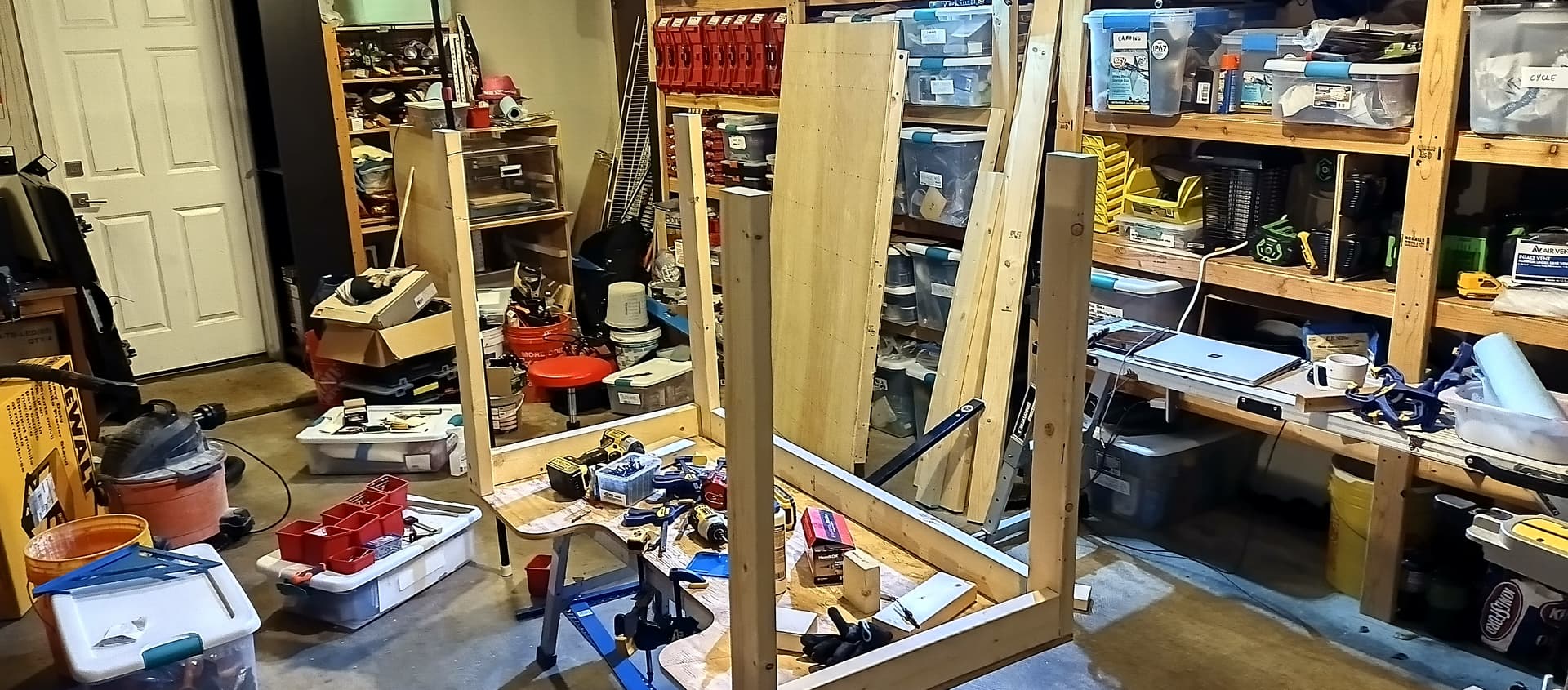
Making progress, but still not ready to cut.

Also, am struggling to let go of the drop table idea. Many folks have made fold away CNC tables. Am curious how many convertible tables are out there? Table where either the middle section lowers (not just a removable sectionable), or, the main top torsion box flips out of the way to expose a drop table setup. Examples/ideas appreciated…
1 Like
It doesn’t even need to be that complicated. You can just get two rails that are thicker for each side of the LR. Something nice and flat, like a stack of mdf strips.
2 Likes
Cheers for idea to raise LR rails instead of dropping stock. Want to engrave top ~1" of wood surface that’s ~12-20" high.
Stacks of MDF is less crazy than some of my other ideas. Am digging through Dui’s and others’ drop tables…
1 Like