That’s great news.
I doubt moving it would break the controller. I imagine you’d have to move it pretty quickly or drop it or something to do damage.
Maybe it was just a bad PSU. That does happen. @Ryan, WDYT?
Bad PSU is possible. What is your order number?
One thing to try is bend the little plug prongs out in the brick a bit to make sure they are making good contact with the power plug.
24456
I will try bending out the prongs tonight.
Sure enough, I bent the prongs out and viola! 24.4v out. I was able to home all axis and manually drive it around a bit.
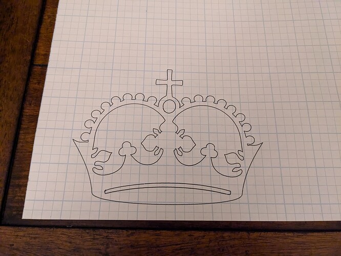
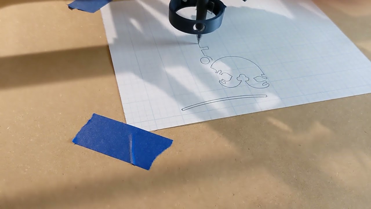
I have it all setup and loaded with the crown test. I unfortunately ran out of time tonight, so hopefully tomorrow I can hit play and post my crowning achievement.
awesome!
We have success! Once I found the g code command to change the origin it went very smoothly.
I realized I haven’t a clue how to use the fluidnc interface so that will be my next step. Also I’m not sure if the circle is supposed to be an oval or not so there may be some adjustments there.
Overall, I’m very pleased and quite excited. I did hear a bit of plastic creaking sounds from the core so not sure what that is.
Oval for sure.
That is odd, Maybe run it a few more times and see if anything settled and is a bit loose.
In the FluidNC WebUI there are buttons for zeroing each axis at the current location. This sets your origin as needed for any job.
I did take a video last night so I uploaded it. At about 1:05 you can hear the creaking as well as a few other spots in the video. I’ll try to investigate more this weekend. I’m wondering if it may have been my cable loom dragging on something, though it didn’t seem to be like that was the case when I was watching it.
I played around with the parts and noticed that the pen creaks a bit on the mounts and then the wire loom definitely made some sounds that sounded very similar to the ones in the video. I think things are ok.
Once you cut and install strut plates rigidity will improve and any “creaking” should go away.
So I’m trying to do the Z leveling and having some issues. I have a jackpot board that I bought from the V1E store. I zero the machine using the soft key and then manually move it over the probe point. When I send the M114 command it says:
“Error:20
Unsupported or invalid g-code command found in block”
And when I try the “G38.2 Z0” I get:
“Error: 22
Feed rate has not yet been set or is undefined”
Is there some sort of setup I’m missing?
I got the same error, but G38.2 Z0 F300 gets me a valid probe from the Gcode console. Presumably because there have been no commanded Z moves, the firmware does not know what speed you wish to probe at. Probably a good thing it does not use the axis maximum speed ![]() .
.
On the Milling Basics page, it talks about gcode for start, tool change, and ending.
https://docs.v1e.com/tools/milling-basics/#gcode-start-tool-change-and-ending
Typically (at least for me), you put this in your CAM software so its built into generated gcode.
This is the probe line listed for LR3 with Jackpot.
G38.2 Z-80 F200 P0.5 (probe down set thickness )
This assumes that you are homing the machine first. Since it homes to the top, when you probe you’re moving down in the negative direction. So, Z-80 says move down up to 80mm. F200 says use a feedrate of 200 mm/min. P0.5 says offset for a touchplate thickness of 0.5mm. That’s the thickness of the one Ryan sells but you can change that if using a different touchplate.
Hi Pebble,
congratulations on your build! I’m about to start table build similar to yours - my plan is to build torsion box out of 2x4s, and then screw/glue mdf on both sides + metal struts for LR3 to ride on.
Did pine work out well for you? No leveling problems? How many ribs do you have there?
Also question for anyone: Will it make table much worse if I have top and bottom MDF in 3 parts each? I have mdf sheets which are not big enough for the table, so…
Hello Juggler,
The pine seems to be ok for now. I haven’t actually been able to cut anything just quite yet so take that with a grain of salt. I did use a jointer, planer, and table saw to make sure all the 2x4’s were all S4S (square on all 4 sides). Without doing this I’m sure the table would be rather wavy and not as flat as it could be. I also had a large time gap of about 4 months from when I bought the wood to when I started using it, so it had a fair bit of time to dry out, acclimate to my basement and do any warping. It seems fairly flat. I can stick my 6 ft level on it and don’t see any sort of light under it. It is not very rigid and twists very easily on the simple saw horse stands. I am ok with it as this was just a temporary solution to be able to cut a real torsion box with the CNC once it was up an running.
I wouldn’t advise using 2x4’s straight from the store and I’m not even sure I’d advise using 2x4’s for a torsion box at all. Real wood is just a bit too dimensionally unstable and I’d worry about wood movement messing up the box. You could try it out as a temporary solution but it sounds like a lot of effort and time for something that may not work well in the end.
I’m not sure what I have configured wrong but when I home the machine it reports as xyz being at zero, but when I send a G0 command to go to x0 y0 and z0 it behaves strangely. For example the x0 is in the middle of the table and negative values go left and positive go right.
My table also doesn’t look right in fluidnc where the strut image starts in the middle of the table. I can still run the operation and it works going outside the virtual table bounds but I’m rather confused.
Also I feel bad asking these questions as they seem somewhat rudimentary. I try searching for answers in Google and the forums first but it’s difficult to find the right thing sometimes. Is there some tutorial I’m missing somewhere that may help me? I’ve read all the V1E cam and milling basics pages a number of times but I guess I’m hoping for more.
How are you generating the gcode? What are you using for CAM software? It sounds to me that you don’t have that configured properly. Around here, Estlcam is very popular. Some use Fusion 360 but that’s a bit more complicated.
On the milling basics page, it lists this as the starting gcode which does some important things.
I’ll give a description but you can also refer to this:
Supported Gcodes | Wiki.js (fluidnc.com)
G21  <= Use millimeters for length and speed values
G90 <= Absolute distance mode.  When you specify X,Y,Z, it's going to that position, not moving by that distance.
G94 <= Units per Minute Mode.  This is default.
G92 X0 Y0  <= This is setting the current position to 0,0 (X,Y).  I think this is what you are missing.
M0 (MSG Attach probe) <= Create a hold with a message to attach the probe.
G38.2 Z-80 F200 P0.5 (probe down set thickness ) <= Probe Z as discussed before
G1 Z10 F900  <= Move to position of Z 10 at feedrate of 900 mm/min
M0 (MSG Remove probe) <= another hold and message to remove probe
M62 P1 (If used start spindle pin27 ) <= unless you have a spindle (not a router), this doesn't do anything
Don’t worry about it. This is a safe place to ask questions. We were all new once. I’m still fairly new.

