Orob's Z-brakes board for the belted z bed

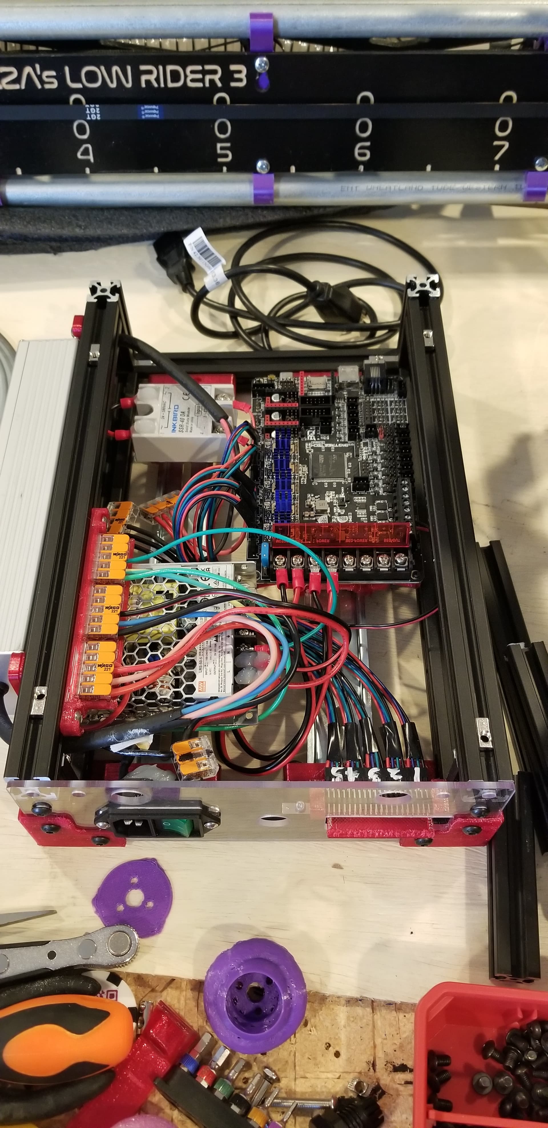
This board is grass roots effort stemming from testing out what conditions work for brakes on the mp3dp v4. See the use z-brakes thread for the back story if interested.

When tuning and setting up klipper, a processor restart is required to implement a new change. If the system was homed, then there is an opportunity for the bed to drop. Bed crashes can occur from

  • power outages
  • emergency stop conditions
  • faults
  • even at the end of successful prints if slicers and end_print macros are not carefully set up

An uncontrolled drop can impact and scare you at the least or lead to cracked parts or even cooked control boards in extreme cases depending on the weight of the bed or gantry. This board is a little insurance to protect the expensive electronics and minimize mechanical impact.

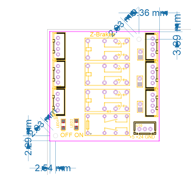
Inputs with screw terminal connections:

  • 24v
  • Ground
  • 5 volt signal (recommend unused TFT TX pin)
  • motor wires to control board such as octopus, or manta.

outputs with screw terminal connections:

  • wires to z motors

The brake board takes 24 V input from your printer power supply, ground, and then it uses a 5 V signal from an mcu pin such as the TFT TX pin recommended if using klipper and a BQ/BTT board since the BQ TFTs are not klipper supported and that pin does not have any additional clamping or pull-up circuitry on it.

How it works:
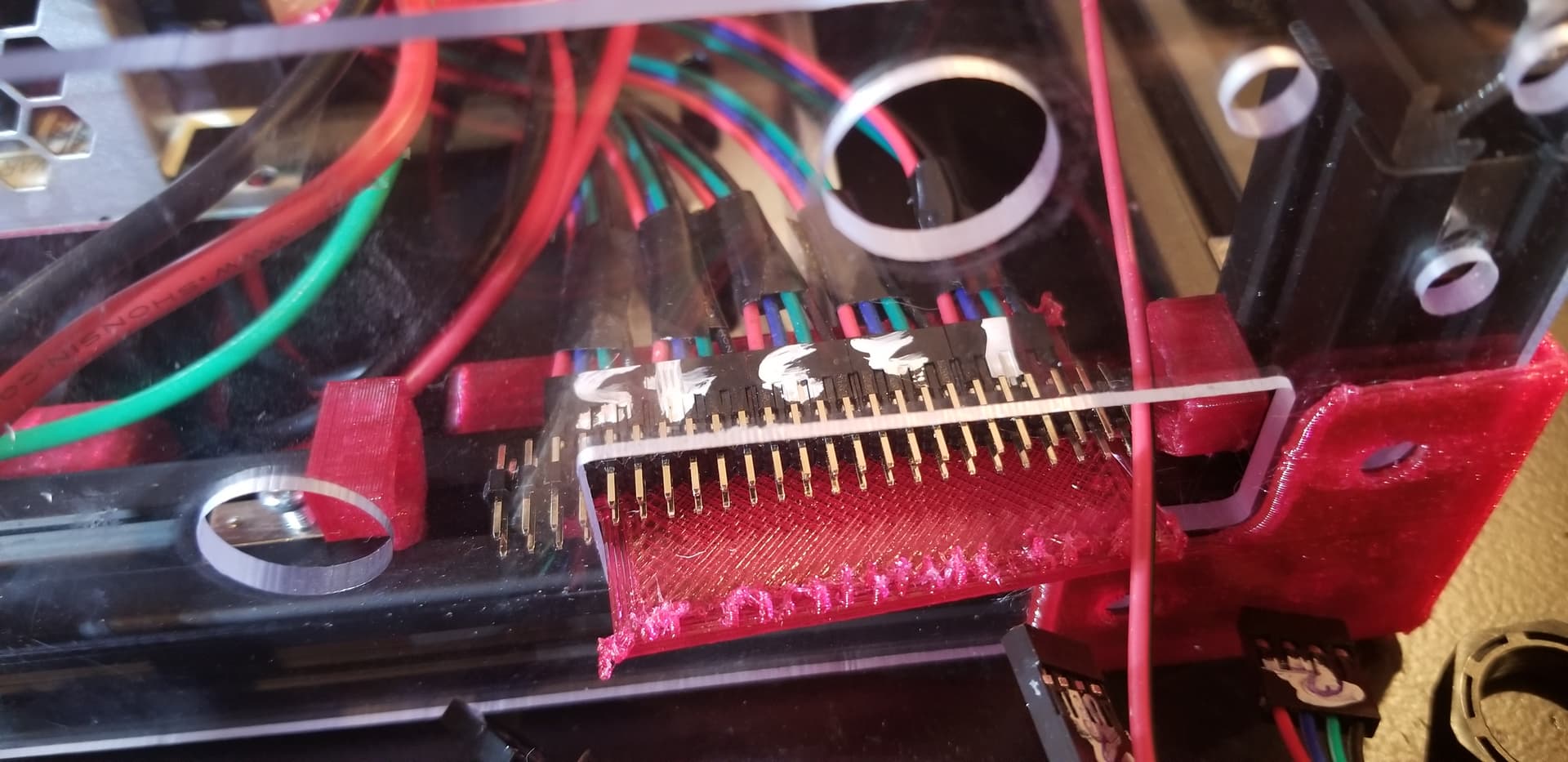
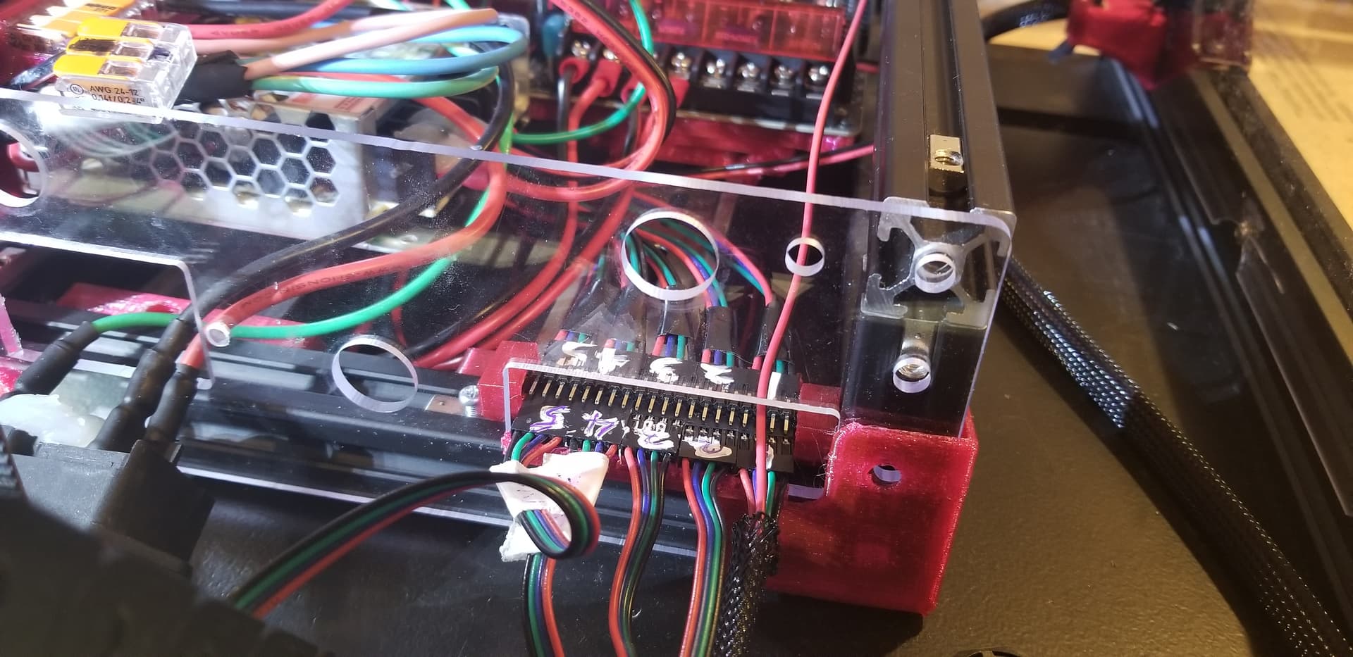
Brake board is a pass-thru for the stepper motor wiring between the stepper driver and the stepper. The brake works by shorting one or both stepper motor coils for each motor connected when no power is applied to the signal pin. If the 24v line has power, the red led will be on to show brakes are active until a signal from the board processor turns off the brake, which is signalled by the green LED and the motors will then function normally. If either the 5V signal or the 24v motor power are disrupted then the brakes are activated.

A jumper is included for each stepper to brake both coils or just one from each motor. A single motor coil brake is much louder of a buzzing as the bed moves than the two coil drop, which is very quiet.

Klipper code to add:

[multi_pin z_enable]
pins: !PG5, PA9  # on octopus, !PG5 is the driver pin pulled low to enable TMC2209 z stepper, PA9 is TFT TX pin

[stepper_z]
enable_pin: multi_pin:z_enable # this used to be !PG5 , but with the multipin, they both activate simultaneously

not yet confident in the documentation notation, so this is here for now. I’ve forked the docs and have a pull request in the works.

2 Likes

@orob cheers for designing, testing and documenting a neat ebrake board. Feels like something many belt based printers would benefit from…

Noticed for sale on v1e…
ORob's Stepper Brakes – V1 Engineering Inc

Do you have board spec/diagram somewhere? Planning to order one, and am trying to figure out how to DIN rail mount in my controller box.

Cheers!

2nd this one. Mine shows it should be delivered tomorrow :partying_face:

You want a board dimension to make a mount for it? I’ll post a drawing a little later tonight.

2 Likes

This looks way worse than it is:

I imported the cut and pasted board from the design software into coreldraw and tried to dimension it there. I am not versed in cad well enough to do it there in a few minutes like this, but these numbers didn’t offset correctly and it just looks terrible. The outer cut line is a double line and the outer board dimensions were off by just a little, so I’ll list off the interesting dimensions:

  • X and Y are 50 mm for the total board size
  • the 2 mounting holes are 2 mm in diameter (not ideal I know. Ryan and I discussed how they should be larger to use any meaningful attachment screw, but for a din-rail mount, perhaps you could make a printed pin and a flex clip to hold it and not use a screw.)
  • the upper right hole center is 9.15 mm from the right side of the board and 3.5 mm from the top
  • the lower left hole center is 2.5 mm from the left board edge and 2.25 mm from the bottom edge
2 Likes

Cheers for the dimensions @orob, that helps! You planning to open/license the design?

Currently, I have this janky printed gets the job done wire connector extender on my controller…


Upgrading to a PCB based connector has been on my list for a while. Ideally, would like to replace with something that incorporates an ebrake design. So, I’d like to try remixing your ebrake board for 2020 mounting via M3, but also extend wire for the XY steppers as well. Dual purpose, hoping this’d leave my controller interior space free enough for some of the Chameleon stuff am trying to cram in without changing the controller box foot print.

No worries if your looking to sell your ebrake board. Personally I think you should, it’s helpful for others with belt printers, not just MP3DP. Cheers!

PM’d you info on the board.

Have you got the printer back in operation at home since taking it to RMRRF?

Nice. I’ll need to put one of these in my shopping cart for the next time I order stuff.