I’ve remixed the excellent “blank case control box” model provided by Ryan, to support SKR Pro 1.2 with TFT35 E3 and with two cooling fans. It also has openings for accessing the main board’s USB slots and SD card slot, and an opening for accessing the touchscreen’s SD card slot.
I’m currently printing it, and it’s a pretty big print run, so hopefully it will come out as desired and not need redoing.
Below is a screen shot and the model parts with print times, which are based on .3 layer height and .6 wall width. I’m accomplishing that print spec with both 0.4 nozzles and 0.6 nozzles.
Part
Print time
Grams of Filament
Base
11h 34m
182g
Lid
6h 20m
106g
TFT Holder
4h 21m
73g
Reset Button
0h 4m
1g
UPDATE (2022-06-06): I switched the orientation of the touchscreen. The following are updated screen shots.
The original design was like yours, 3 parts design… bottom/front, Top/back, screen and no emergency bottom. Now, this is a 2 part design as I have to move the screen forward to accommodate the big stop bottom.
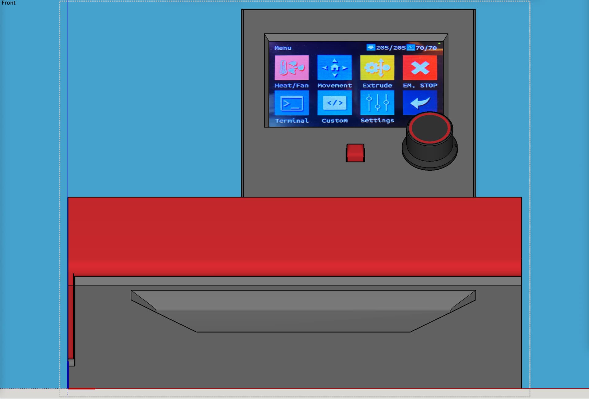
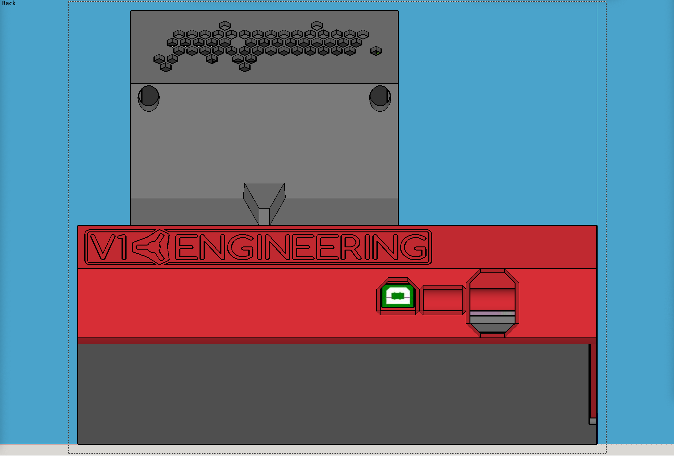
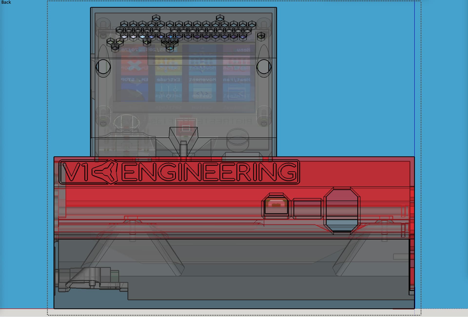
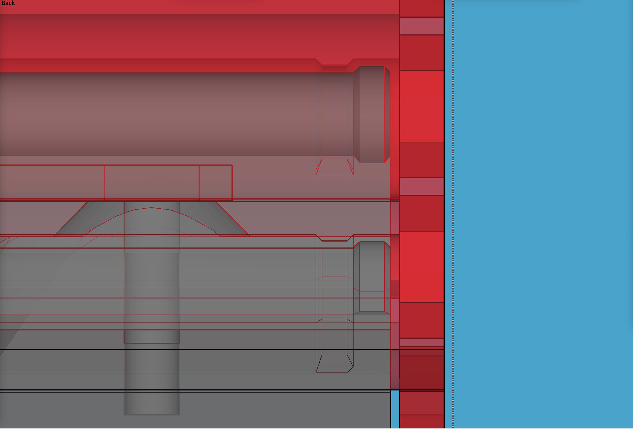
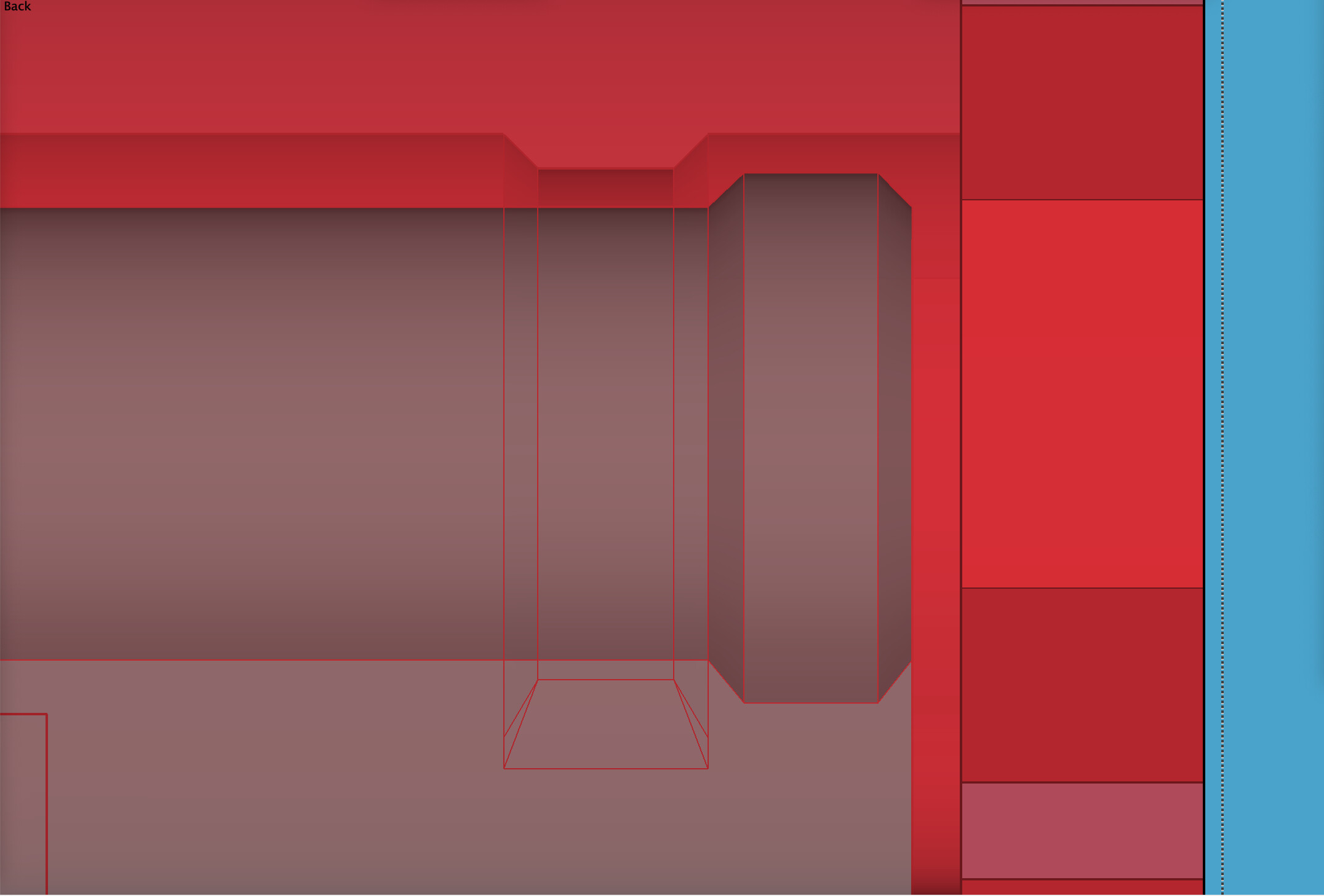
I’m trying a little something on the case. A “snap in place” touch. On the two “rails” on the base that slide into tracks on the lid, I added 0.35mm bulbs, and corresponding ridges inside the tracks on the lid to constrain when the bulbs snap in. Will let you know how it goes. Should have some prints in due time. Here are screen shots to get context and then zoom in:
More screen shots of 3D modeling for my remix of the V1 case CAD files to suit SKR Pro 1.2 main board and BTT TFT35-E3, this time showing the DC connector “sled” and “clamp” - and the exterior view where the power cord plugs in.
Got my Y rail installed on my metal strut. Drilled and tapped the holes. Pleased with how it came out. Case parts for my SKR Pro 1.2 and TFT are almost done printing.
It looks terrific - I think you “know” me well enough to know that when I say I was thinking of doing similarly - I was! (without the strut). I think the “brace” really looks as though it’s part of the machine.
I suspect in the end I will extend the table in both directions or quite possibly even simply build a new one which might actually involve less work.
…The link I posted above should be clickable to the Printables download page. Same here in this post too. Let me know if that’s what you were meaning and if you’re having any difficulty.
I got out a brand-new bit, 2-flute, up-cut, flat end mill, and still had tear out like crazy when cutting this 1/8” thick hardboard. I used a 1 mm depth of cut. This happened for me both on the LowRider 2 and the LowRider 3.
Up cut will always tear out the top. Need a down cut to prevent that. Just have to be careful with cut starts, since for a bit there’s nowhere for the chips to go. Ramp into cuts work to fix that.
@vicious1
Thanks. I guess I could cut these struts out of 1/8” hardboard in a single pass instead of multiple passes. I think what Barry said about not using an up-cut bit may help too.
@vicious1
I got my SKR case done and after putting it together I realized that I would rather the lid not have a hole for cables but rather just stop short and leave an opening at the bottom, because as it is I had to route the wires through the lid before the lid was in place and then slide the lid on the wires to put it in place, and since my wires are inside a plastic wire hose which is a little too big for the hole it was a pain to put it in place. Then I had to take it apart and put it together a couple of times to get my motor directions right, and I’m gonna still have to take it apart and put it back together once I get to checking the end stops. So I think instead of having a hole in the lid for cables, I will just have basically an opening that leaves a gap at the edge so it’s more like a hollow place that allows the lid to the installed and removed without having to slide it along wiring.
Also, I’m going to turn the TFT holder back to same orientation as on my previous box on my LR2. That one had X- and X+ oriented with X axis, and Y- and Y+ oriented with Y axis. This one, as is, has them perpendicular, and although I can account for it in my mind, it make things slightly annoying. Plus, with my table designed like it is, accessing the buttons is not easy when I am standing on the X axis end of the table (screen is facing out away from me then). A 90 degree turn will correct all this.