I want this under the glass of my dining or coffee table. How fricken cool would it be to have it draw the map for a DND game?
5 Likes
That is a new one! I love it.
1 Like
So… give the DM access to Octoprint loaded with gcode files for sections of the map, draw as the party advances and they can see new areas?
2 Likes
Exactly! Is it more complicated and slower than a monitor build in to a table? Sure. But would it make for an awesome game night? Absolutely!
2 Likes
Does anyone know if the Tindie 2Ch board from BDring (https://www.tindie.com/products/33366583/tmc2209-penlaser-controller/) could be used to control addressable LEDs?
The board itself provides access to one entire header of the ESP32, so I think grabbing a GPIO would be easy (there appears to be 4 unused in the schematic). Where it gets hazy for me is the FW and web interface. It would need to be modified to add the code to control the colors and patterns.
The LEDs themselves can be powered separately, ideally with the same 12V source that powers the control board itself.
Thoughts? I am not well versed in ESP32.
1 Like
God, this is inspiring! I can’t wait to get mine going.
3 Likes
The part that is missing is the software. You wouldn’t have to edit the interface, you could control it from gcode or $ commands. But you would need to add in the fastled library and then create the patterns and set up the pin.
I chose to just get a second esp32 and install wled on it. There is no syncronization, but wled is so nice to use.
2 Likes
Yeah, I could do that, but I like the idea of keeping the hardware to a minimum and hidden out of the way. For what it is worth, the board developer seems optimistic. I sent Mr. Dring a message on Tindie and this was the reply:
"I believe the firmware could be modified to add addressable LEDs. The firmware allows for custom code. There is a custom folder where you add your own code. There is a simple example of a simple OLED display. You would have to write the code for the LEDs and put it there. Study the OLED code.
The controller does have a few extra pins that you could use.
We are currently working on a major update to the firmware, so the primary developers don’t have the time to work on features like this.
Here is an invite to our Discord server. There is a channel on user customization. You might find others to help you with this idea."
I like the line where the FW has a built in section for custom code. I think I am going to get a roll of the addressable LEDs and play around with it. Worst case scenario, I grab another ESP32 and do exactly what you did, Jeff. I dont even want synchronization, I just want to keep things compact. My table is on hairpin legs, so I want to keep the part count low…fewer things to hide. THanks!
1 Like
Well, you should definitely check out wled anyway, even if it is just for testing and inspiration.
The ws2812 leds and the like take about 60mA per led at max brightness (but it varies). So you will need to give it the raw power anyway (not through the board). Find the 12V versions.
1 Like
Yeah, definitely need to keep the LED current off the board. I am hoping that I can supply a single 12V source to the table to drive the Controller and LEDs in parallel…this way I can have one wire discretely zip tied to a table leg. I still need to do the current requirement calc for the power supply.
1 Like
I completely understand what you are looking to do. Pretty sweet that it sounds like it could be easily possible.
I agree with Heffe, you have to at least play around with wLED. I love, love, love being able to change the mood of the table on the fly with it.
I currently have it set to boot to a nice mellow slow pattern, but when I need to I like to log in and show off the list of favorite patterns. When you do get it going in GRBL make sure to leave some room to swap patterns or at least colors by gcode on the fly.
I tuck all my boards and wires on the end nearest the limit switches, there is plenty of room for me, one power cord down the leg. I will take some pictures soon as I get it real nice. I am still doing some minor messing around with it all. I messed up and got the 5V version so I am trying a buck converter. to eliminate the 5V wall wart.
I just completed the mechanical assembly of all of the ZenXY2 components. I was very impressed with the design. It went together just as intended. My only hiccup was a minor one. The flag mounting holes on Truck 1A are just a bit loose for the intended M2.5 screws. The holes are modeled at 2.5mm diameter, which is exactly the same as the optical sensor mounting holes. The screws bit fine in those holes so it is probably just my printer tolerances. Great work!
1 Like
Some slicers have hole compensation which is a pain. I design for the way most slicers work which is slightly undersized holes. The fix is a drop of loctite or any kind of glue will usually work perfect. There should be absolutely zero load on them at any time.
Thanks for the kind words!
The nice part is that the string I bought was 16ft, and I only need about half for the zen. I have quite a few leftover ESP8266s from my weather station project, so I can play around with wLED with the excess. Perhaps I will make something for my son…
Thanks!
Ok, I just watched a video on wLed. I get it. If I add my own code to the controller board FW, I will have to develop all my own effects and controls for the lights.
All of that is done in wLED, just configure and go. That’s pretty powerful, and may be worth throwing a second ESP in the table just to handle the LEDs.
3 Likes
You can always flash it on the esp, or an esp8266 and then flash it to grbl later. It won’t hurt it. It really can do a ton of fun things. But even something like turning the lights off at 9pm is something easy to do in wled and something you’d have to write a few dozen lines to do on the grbl, and then test and debug any issues you added … It isn’t impossible, but…
1 Like
So I have already installed the Zen and tucked everything away all nice and neat…is there a pinout for the optical ends stops somewhere? I dont want to have to pull a module if I dont have to.
They look very similar to these I found on Amazon…can anyone confirm?
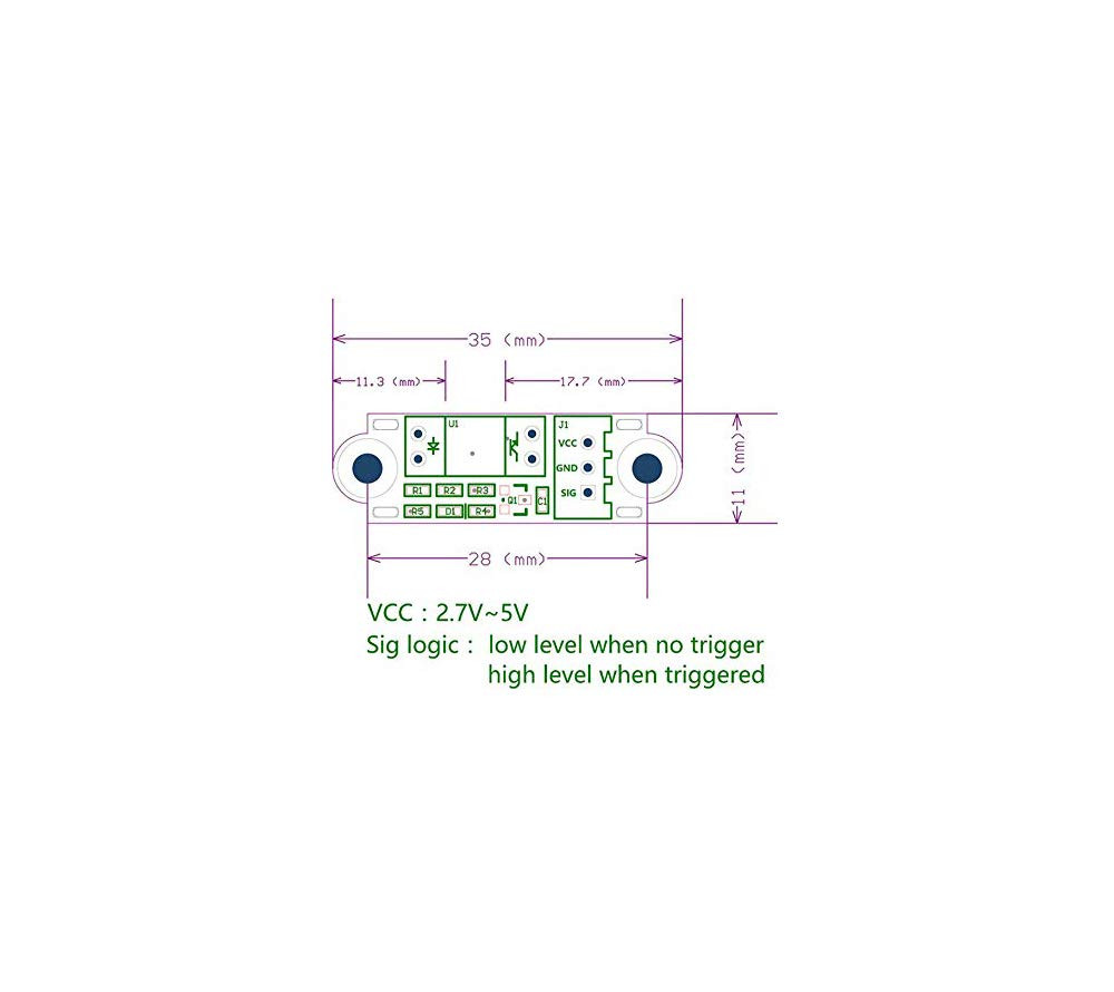
[edit to hold question until further testing is done cause I’m an idiot and looked for firmware configurations in the “firmware” section of the controller product page instead of the “controller” section]
They do look the same, and the pins are labelled on the back of the PCB in that same order, VCC, GND, Sig
1 Like