I think you hit the nail on the head right there.
Unfortunately, my engineering style is to design something with as much control/flexibility as possible from the start. After the design goes through its paces, I then start removing parts or functions that aren’t needed. So I can honestly admit that I initially only wanted the ability to control the motors individually for the sake of being able to. Now that you pointed out the auto-squaring function, it’s going to be part of the design.
I often build things that are overly complicated for the challenge and experience. This isn’t a consumer product, so I don’t have to worry about keeping it too simple. I leave practicality at the door when I build devices for personal use. I’m still not sure if that is a good or bad thing ![]()
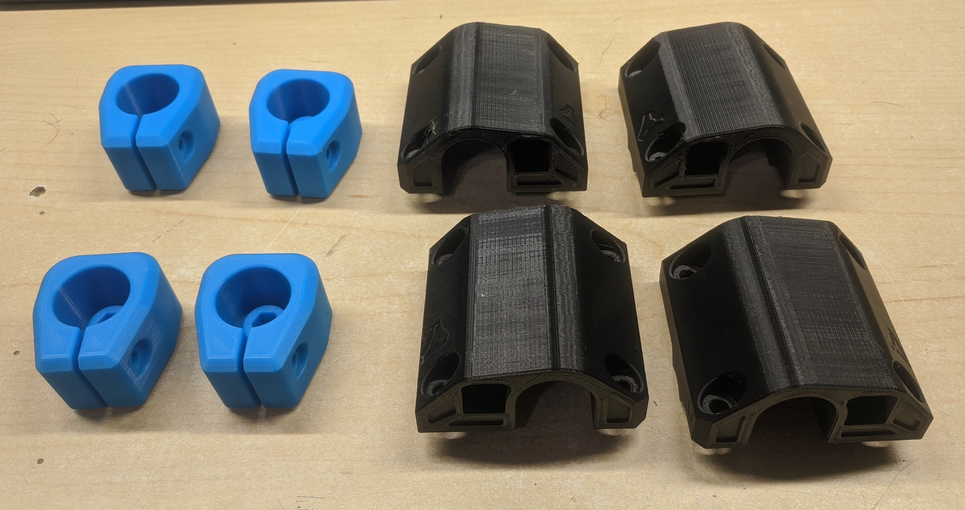
Corner leg locks came out beautifully. I really like the color, and this is newer “PLA+” filament that seems to be much better than my normal PLA. Same print settings, same brand, only a change from PLA to PLA+. The printer is currently working on the corner bottoms, so once those are finished (in about 24 hours) I can start attempting to put things together.
I have a massive piece of wood, it’s about 48"x30" and a little over 1.5" thick that I’m going to use as a base. I want to build the work area to about 16"x32" though I’m not set on that for certain yet. I may end up making it shorter, more like 16"x24" but we’ll see. I just ordered the rest of the hardware this morning, so it’ll be Wednesday before I even have the stuff in my hands.
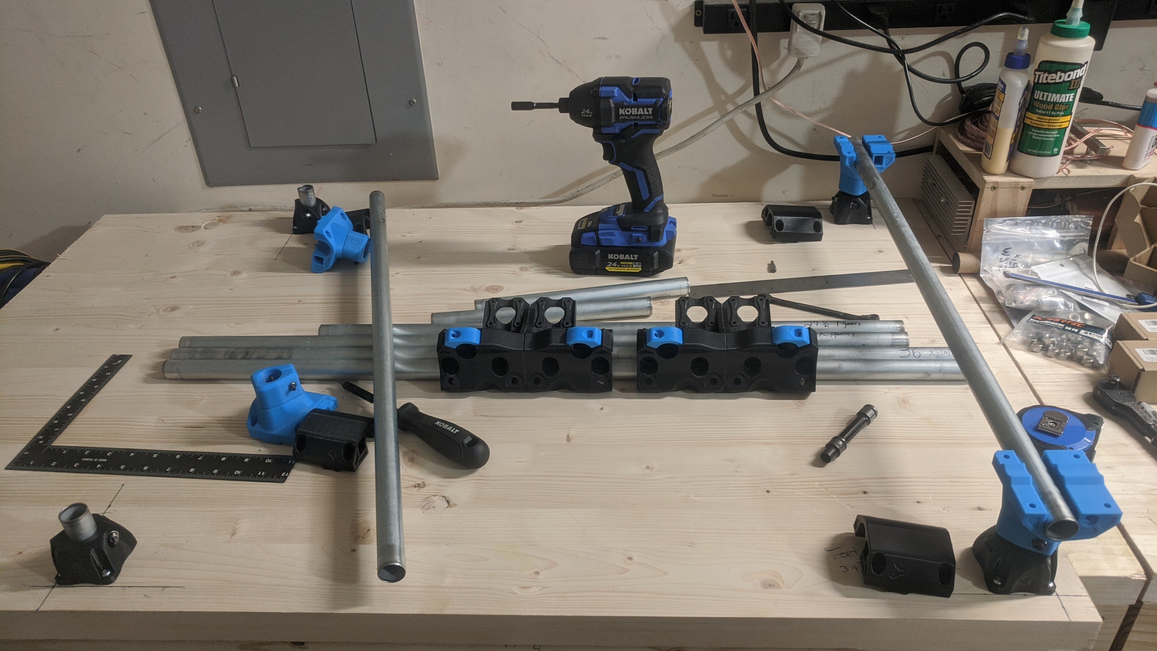
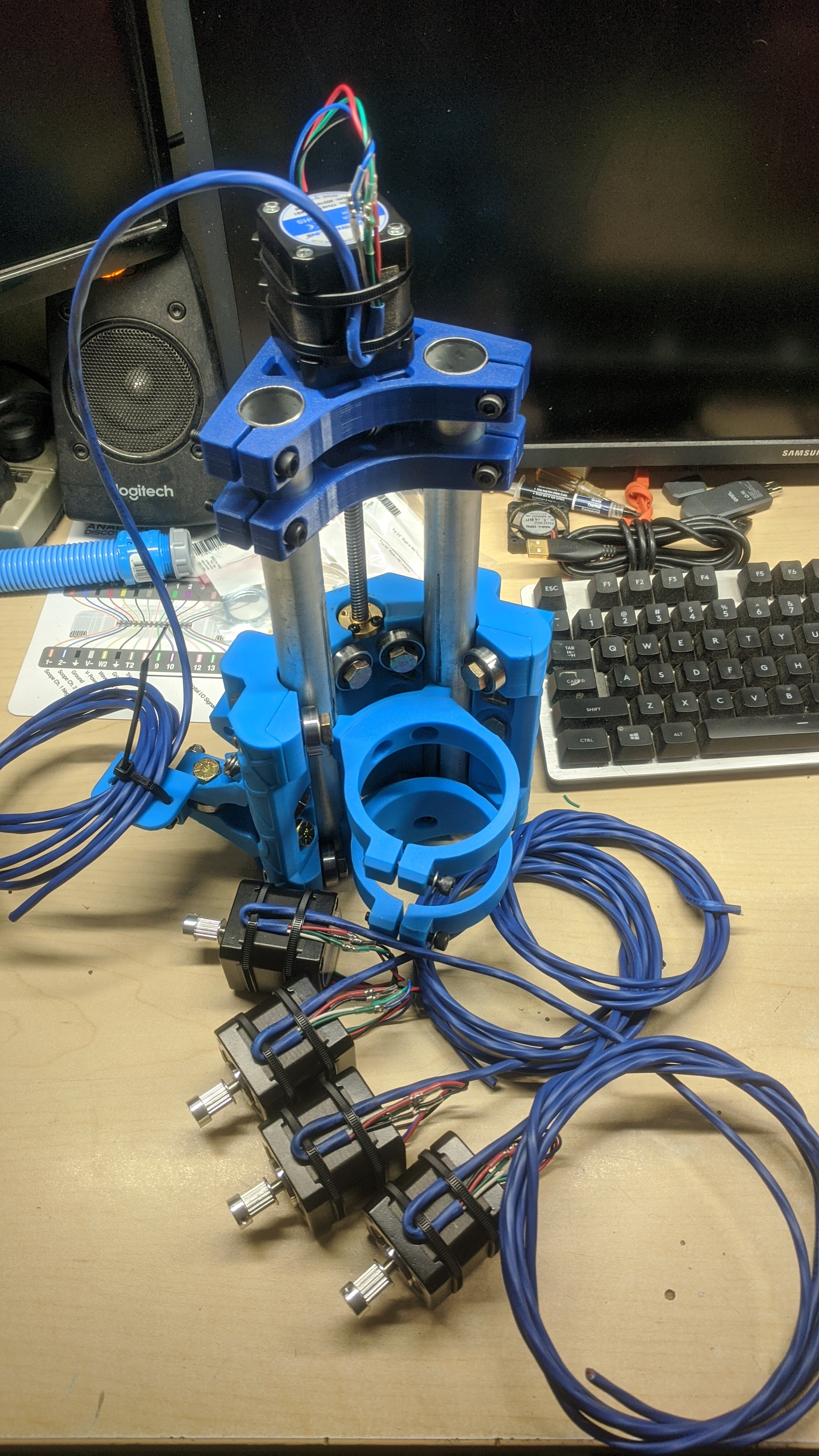
Finally started the assembly. I have everything except for the core and it’s supporting mounts printed, so I can get a good bit of the assembly done. This wkill also allow me to start getting the electronics finalized.
The post office dropped off my parts yesterday, but everything came in about 6 different boxes. Of course one box didn’t make it on the truck, which happened to be the one with all the bearings and the 5/16" bolts, so the CNC trucks get to wait another day to be assembled.
I decided on making it 24" x 17" x 3.25". That will be plenty of space, no need to make it longer. I carefully started measuring out where to install the feet, and got them down. Perfectly squared on the first try! So I continued on with the corner bottoms pieces, installed the Y rails, then put in the X rails. I noticed that while the Y rails were quite flush, the X rails had some overhang. So I kept at it and after starting to bolt down the corner tops, I realized that I measured incorrectly. The left two feet were installed at 33 3/4" not 34 3/4" like I wanted. I used the wrong reference point when measuring 
I needed some sleep so I called it a night. Work has suddenly become crazy busy, and will continue that way for the next couple weeks. I would rather take my time and get everything right than rush it and mess up.
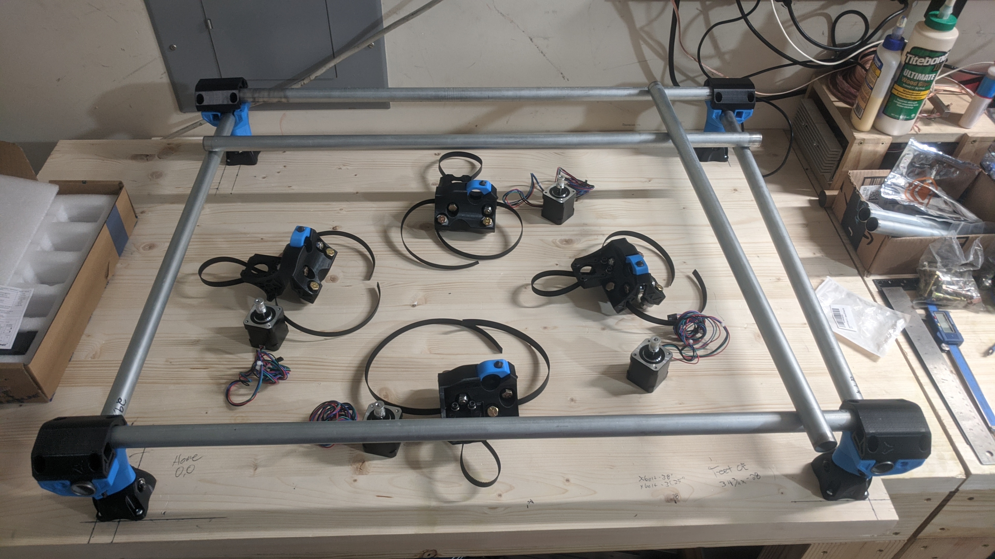
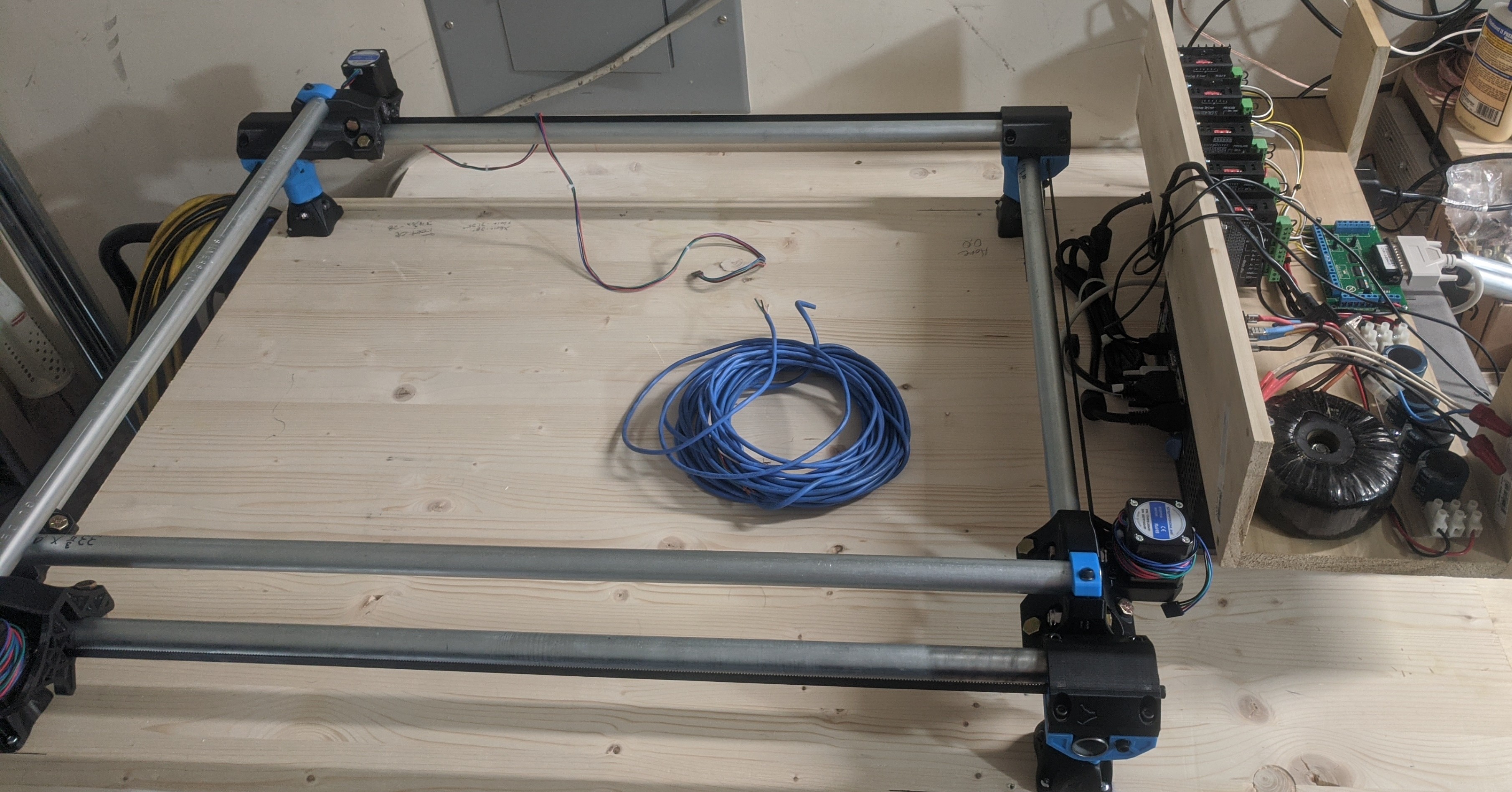
Great progress tonight, everything assembled (not including core parts) minus the y axis belts. It’s looking amazing and I’m stoked to get back at it tomorrow. All parts are in, core is printing in the 3D printer, cold beer in the fridge

I should have the electronics part wired up tomorrow so I can start moving the X/Y axis motors.
Edit: I didn’t snap a photo when I finished for the evening. So this photo doesn’t show all of the progress.
Almost there. I slapped the electronics together into a box that I hastily made. I didn’t even bother putting the top on it, no real need at this moment. The only thing left before I can test run the X/Y axis is to wire the motors to the drivers. This was as far as I got yesterday before taking a break. It was HOT yesterday, so I went back inside. The build is in my garage and gets beat on by the sun in the afternoon.
Core just finished printing after nearly 40 hours. I used a 0.4 nozzle with 0.2mm layer heights. 70% infill. It looks good, but damn that took a while, lol.
Work has been treating me like a dog, so I haven’t been able to do much with the MPCNC. I have almost all of the parts printed now. The last batch of core mounts will be done by the evening, and aside from the cutting tool (I’m pretty well set on the Makita) I should have everything I need. Hopefully I’ll have enough free time (and the energy) throughout this current week to get it functional.
I did wire up the two stepper motors on the X axis just to try it out and I can easily get it to jog back and forth. I was an awesome sight to see it finally moving under power. I do need a bit of help/advice with the calibration.
I’m trying to figure out how much distance an axis can move when a stepper completes one full rotation. Part of the LinuxCNC setup requires various information to be input, but the common setups use a lead screw on all three axis, not just the Z axis like the MPCNC. I can spoof the numbers for it to still operate correctly, but in order to do that, I have to figure out the distance traveled during one full rotation.
I’m using everything that was recommended. GT2 10mm belt, 16T motor pulley, 200 step/rev NEMA17 motors, ect…
If I understand correctly, the pitch of the GT2 belt is 2mm. With the pulley having 16T, that would make one full rotation travel 32 mm? Which means that at 1/4 stepping, a motor runs at 800 steps/rev, which would be 800 steps per 32 mm, or 0.04mm/step.
Does that sound right? I didn’t take the chance to really try any calculated movements under LinuxCNC, I was forcing it to send out timed pulses just to get stuff moving.


Everything is pretty much printed/assembled with the exception of wiring. I have some drag chain, but I feel like they are a bit too bulky and should have gone with something smaller. So at this point it’s going to be up to me to put together some cable management. I’ve been checking out other builds and I see lots of great ideas that I’ll probably use.

As promised, progress came to a near standstill during the past week or so. But aside from this upcoming July 4th weekend, I should be able to put more time into this thing.
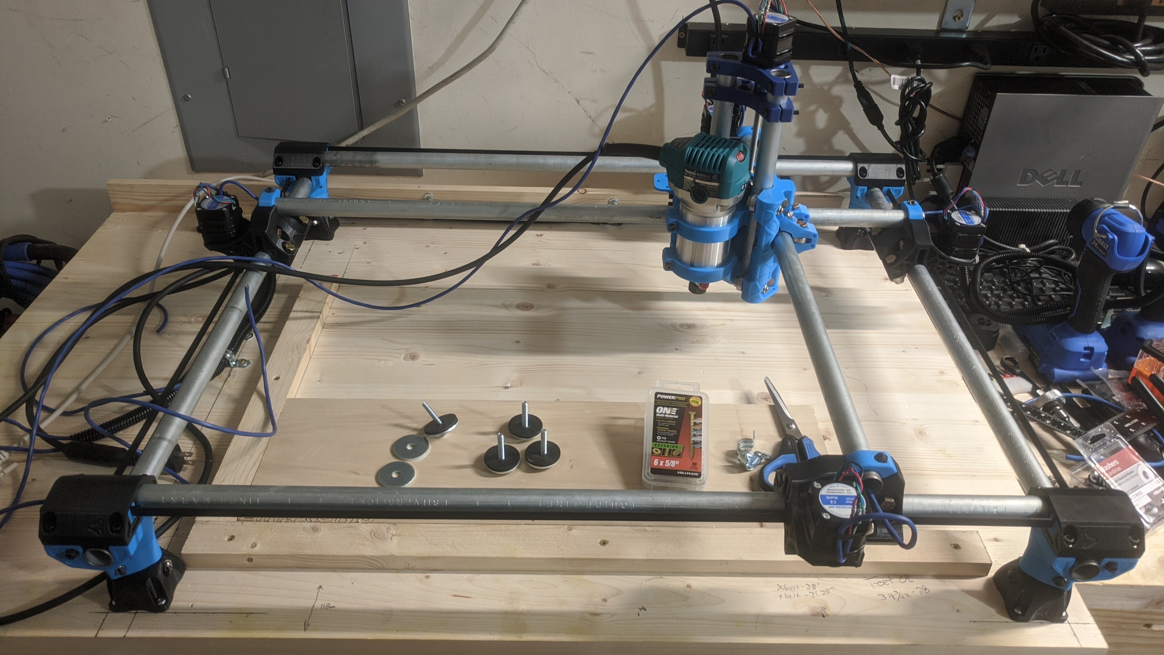
I have everything hooked up, got the Makita router, 1/8" collet with multiple bits (with fast shipping from V1), and even ran a test program on LinuxCNC to see how things work. I didn’t run the router, I still need to put together some braces to hold the material, but it ran pretty well! I have some loose bearing that are chattering, but those won’t be too hard to deal with.
So outside of the braces to hold the material being carved, all I really have left to do is cable management. I pick up some drag chain, but it’s much larger than I expected, so I may end up buying something smaller.
I’ll try to upload a video of it.
Well, video uploaded much faster than I anticipated.
I sped up the video to 2x speed, and lowered the volume a bit. The bearing sound bad, lol.
It works!
I still need to tighten up the trucks and get the cable management taken care of, but I was still able to run it through a quick demo job.
I’m absolutely blown away how well it worked on the first run. It’s smooth sailing from here on out

I’ve done a bit more work on my setup, I put more time into it in the last couple days than the previous two weeks.
I disassembled a lot of the machine so I could make a ton of adjustments. That included cutting the factory wires off the stepper motors and soldering on beefier/longer wires. Everything is much more tight, including the upper Makita tool mount that I forgot to tighten when I first installed it (I wondered where the excessive wobbling was coming from).
I think I settled on a good wire management solution. Flexible wire conduit wasn’t cutting it, but thanks to the more rigid wires to the steppers, basic split loom conduit is working out very well.
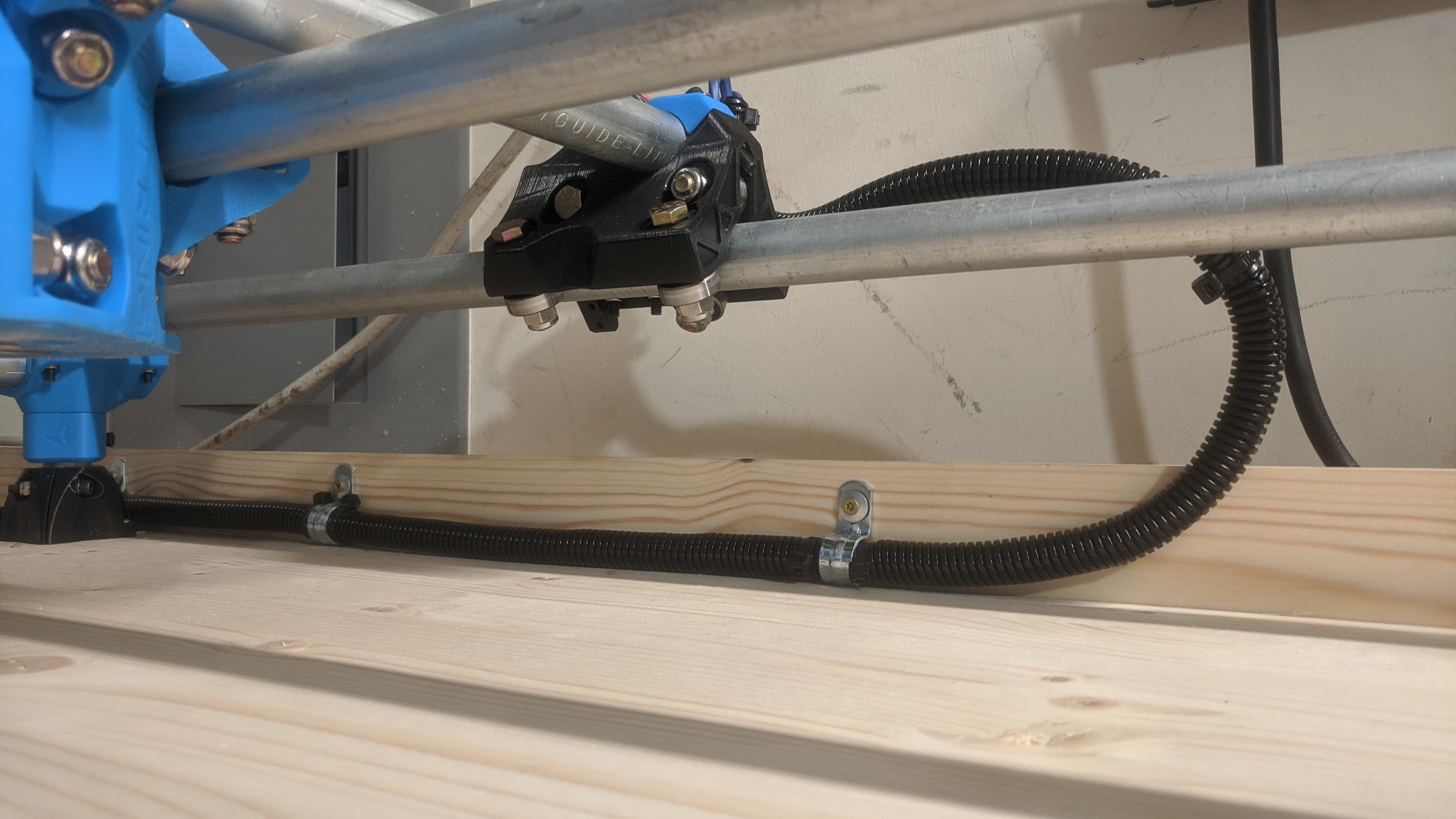
I still need to deal with the Z motor and router wires, but I’m fairly convinced to build an arch over the unit to keep it above everything.
I’ve also got another project going on for my MPCNC. I’ve been keeping it under wraps because I didn’t have much designed, but I should have a good bit available for show here soon. I’ll reveal it soon 
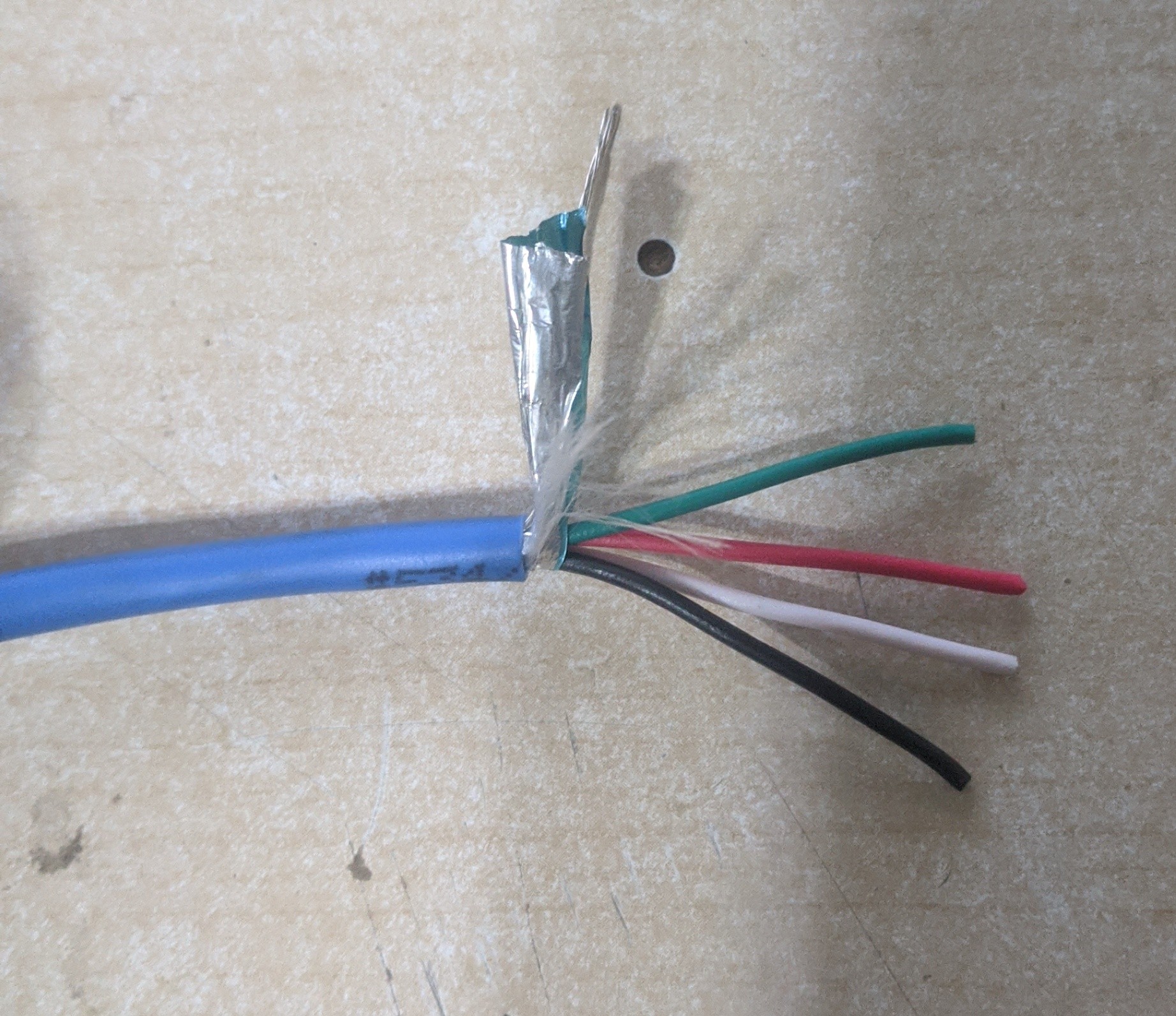
Be careful with that ethernet wire. Solid core can fatigue and break over time.
It’s actually not Ethernet wire, it’s stranded 4 conductor 18 gauge wire. Each conductor has about a dozen stands, so I’m hoping that is enough to prevent too much fatigue. I’ve got a massive spool of this stuff.
So the MPCNC took a bit of a back seat because work had been absolutely insane over the last month. I’ve been working 7 days a week at around 70 hours a week, so my off time has been dedicated to eating and sleeping.
I have poked around with it a little bit.

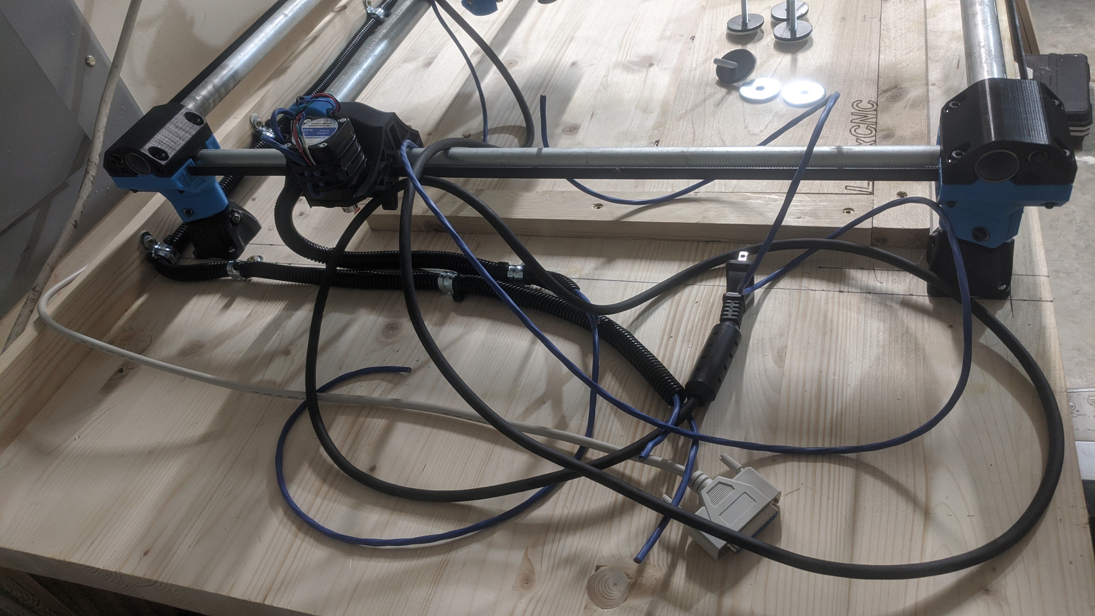
Here is the current condition. Wires are pretty much taken care of and routed around well enough. I want to clean them up further, but that will be for the future after I have it running solid.
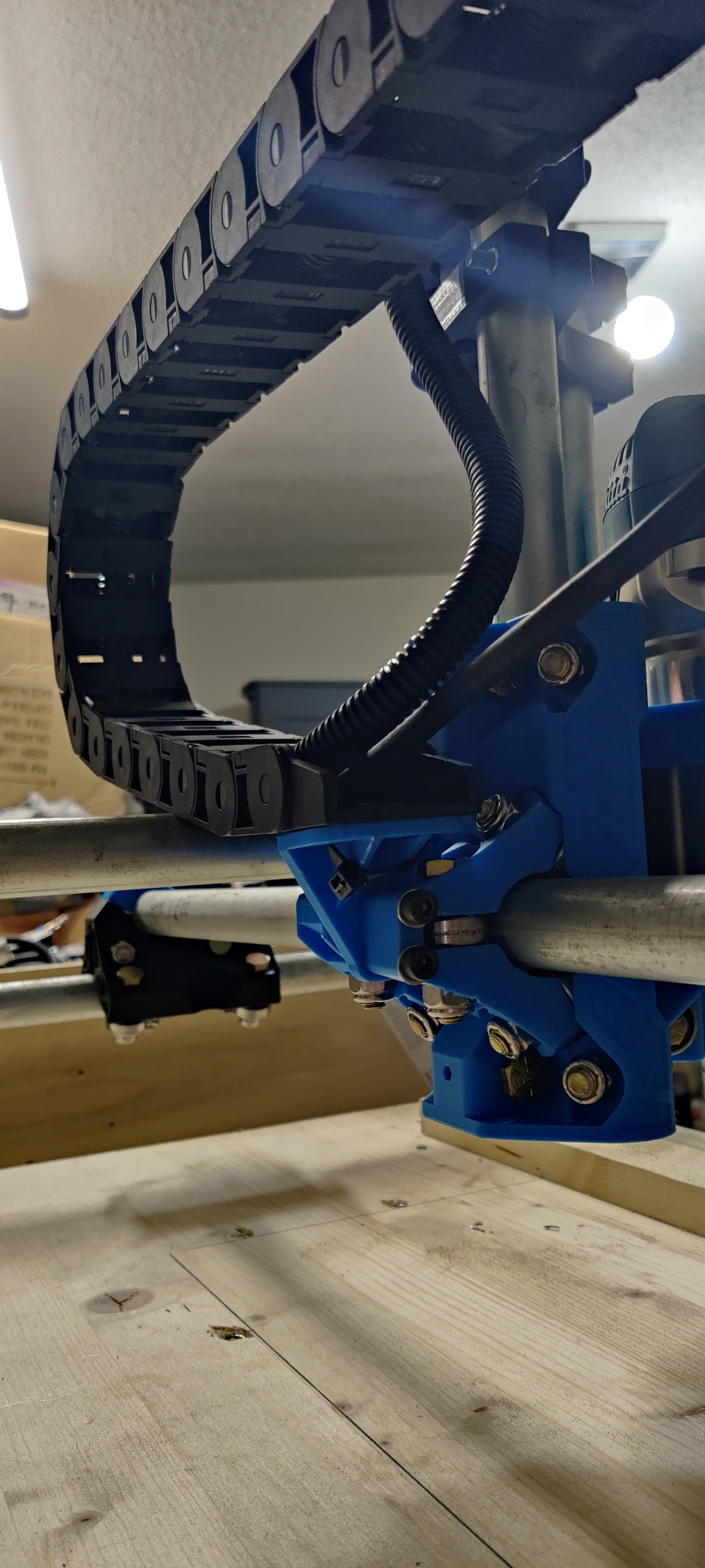
For the Z axis wires, I had made a mount for the core to hold the drag chain. It works well, but the other end on the truck is what has kept me stuck. I finally said screw it last night and did just that…
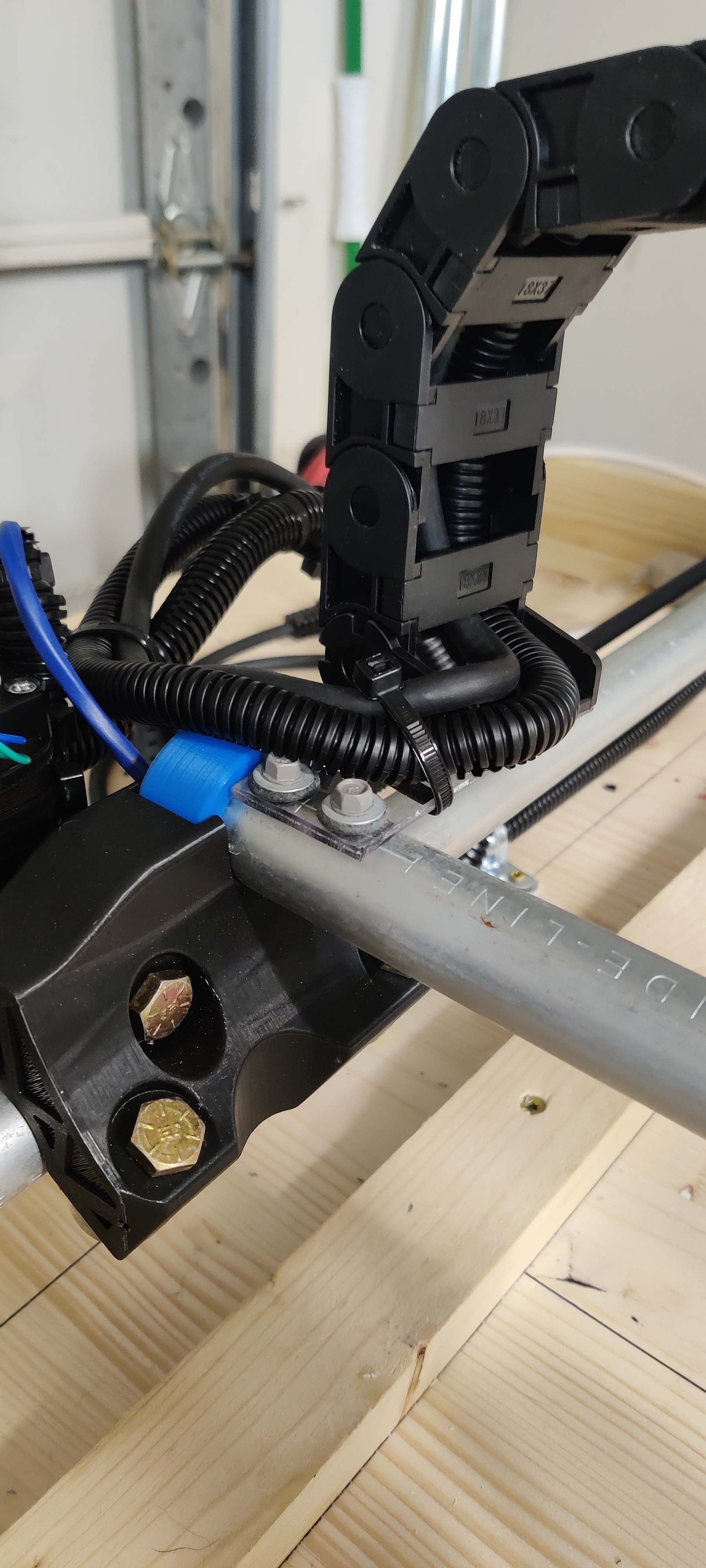
I cut a rectangle out of acrylic, screwed it directly into the gantry rail, and connected the drag chain to it. The wires come out and run along with the other wires perfectly. It’s not great, but it works.
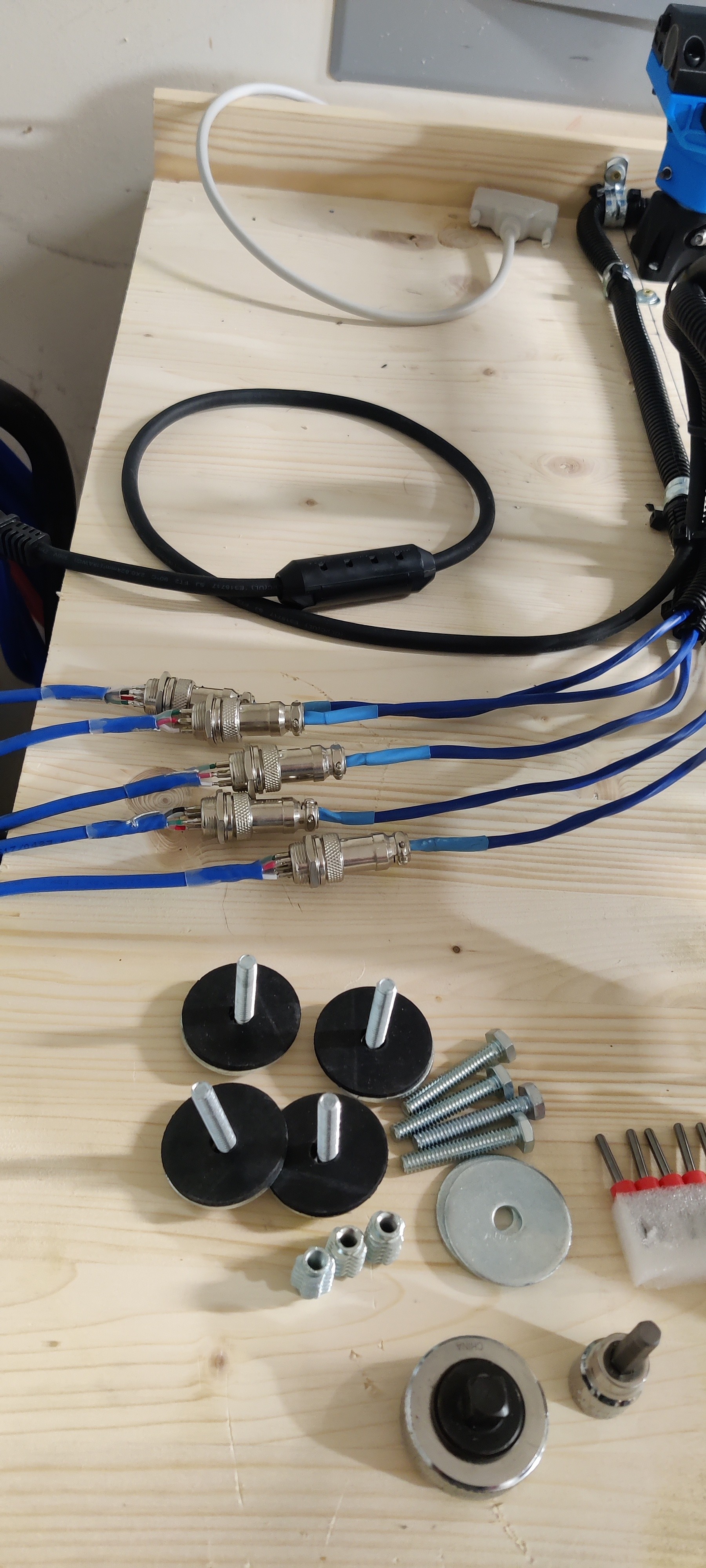
I wanted the motors and router to be able to disconnect quickly, and not with screw terminal blocks. I ended up with aviation style terminals that screw on. Each has 4 pins for each stepper motor. The router will keep it’s plug and I’m going to build a normal electrical socket into the driver box.
At this point, the MPCNC is ready to go. I’ll make some changes in the future, but mainly to clean up stuff. The driver box is functional, but now that I understand how the interfaces work, I’m going to build a more suitable case for it.
FINALLY! Someone else using the provisions on the core clamps for a drag chain solution! I was starting to think that I was the weird one for following Ryan’s advise and not attaching the drag chain to the Z tower!
I made a plug mount system for the gantry tube end for mine. A split plug goes into the tube (With room for the wires going across for motor and endstop) that holds the outer end of the drag chain.
Yes! I really looked over your build and liked your drag chain system. I’m not a fan of plug mounts in general, so I was trying to make a clamp to 3D print to secure onto the gantry rail. The area I have mine screwed into is a dead zone that doesn’t interfere with the core range of movement. I got irritated with not being able to put a decent design together, so I just cut out the acrylic in a fit of annoyance. Turned out half decent lol!
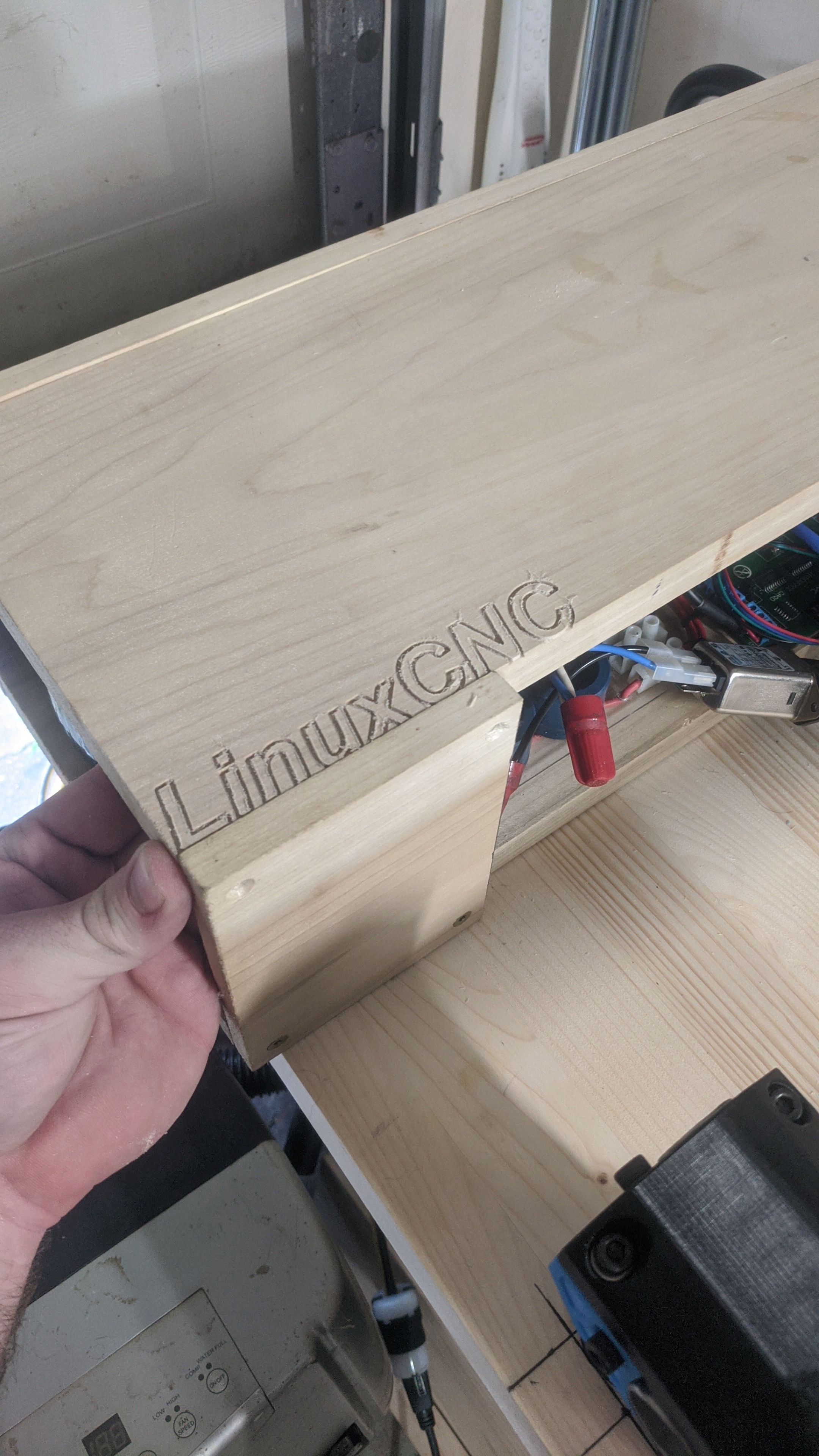
I also decided to rebuild the driver box. It houses the power supplies, Linux CNC parallel port interface and stepper drivers. Everything was pretty much screwed down to a piece of wood for testing, so now I’ve gone back and made it neater, smaller, and overall better.
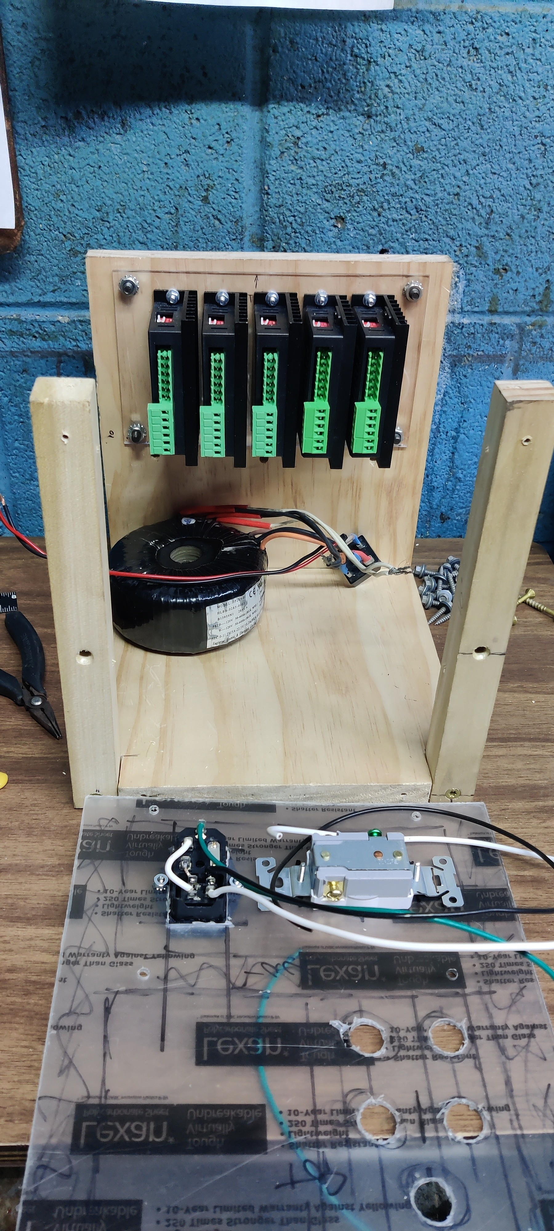
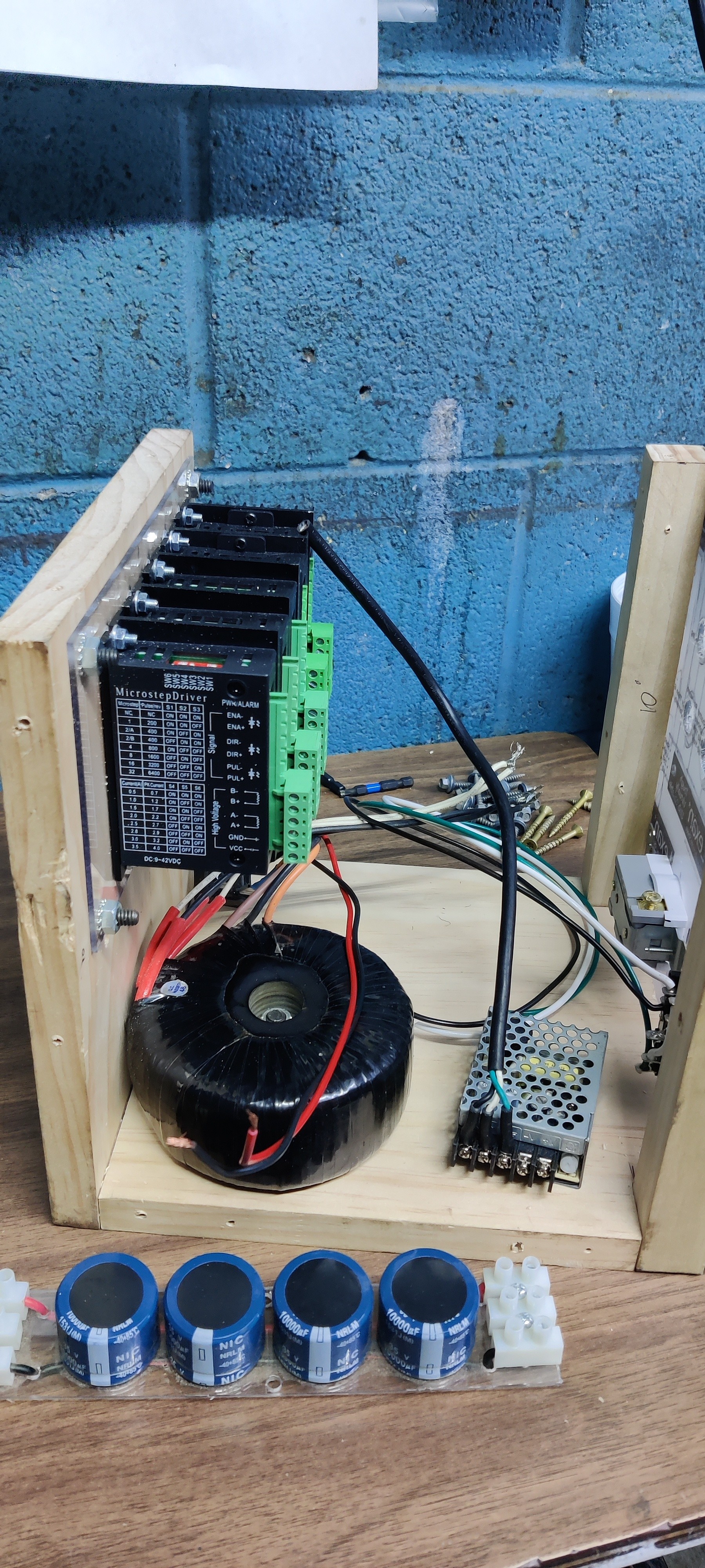
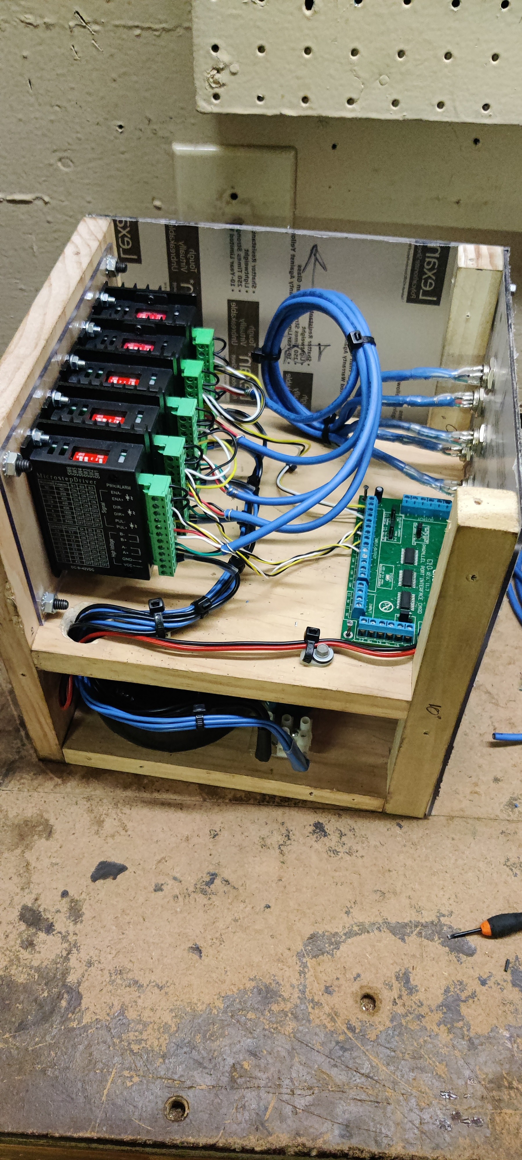

It’s actually almost done already. I mainly need to verify the proper motor coil pairing so all of the motors spin the right way, then I can peel off the protective covering on the Lexan.
Once I finish this bit, everything should be 100% for the whole system, so I can start destroying bits. I mean milling stuff.
Welp, I figured this would happen, but luckily its not a major deal. A part finally went bad.
One of the five stepper motor drivers in my driver box decided to go crazy. I hooked up the driver box to my MPCNC, fired everything up and started to calibrate the axis. X and Y went smoothly, but the Z axis went bat shit crazy. Rapidly moving up and down and just loosing its mind. I swapped two of the drivers and sure enough, the Z was fine with one of the Y drivers.
Oh well, already got another one on order from Amazon… should be here in the next couple days. Nothing really lost, the drivers are cheap and its going to be HOT this weekend where I live, so I won’t be doing much in the garage. Since I know everything will be good I’ll be able to put the finishing visual touches on the box in time to bolt the new driver in and fire away.
Maybe I should put a fan in the box to keep the drivers cool…
Or an E-stop button?
No brakes on this train!!
Been out for some medical stuff, but luckily that’s over for now.
Got the replacement driver for the motor and got it all put together. Recalibrated LinuxCNC and ran a quick program.
Video is at normal speed, I was able to speed it up a bit from when I was still goofing around with things.
I used Estlcam to convert a jpg of a Corgi to tool paths. My mom loves corgis, so I made a “coaster” for her as a test. I use the word coaster very lightly.
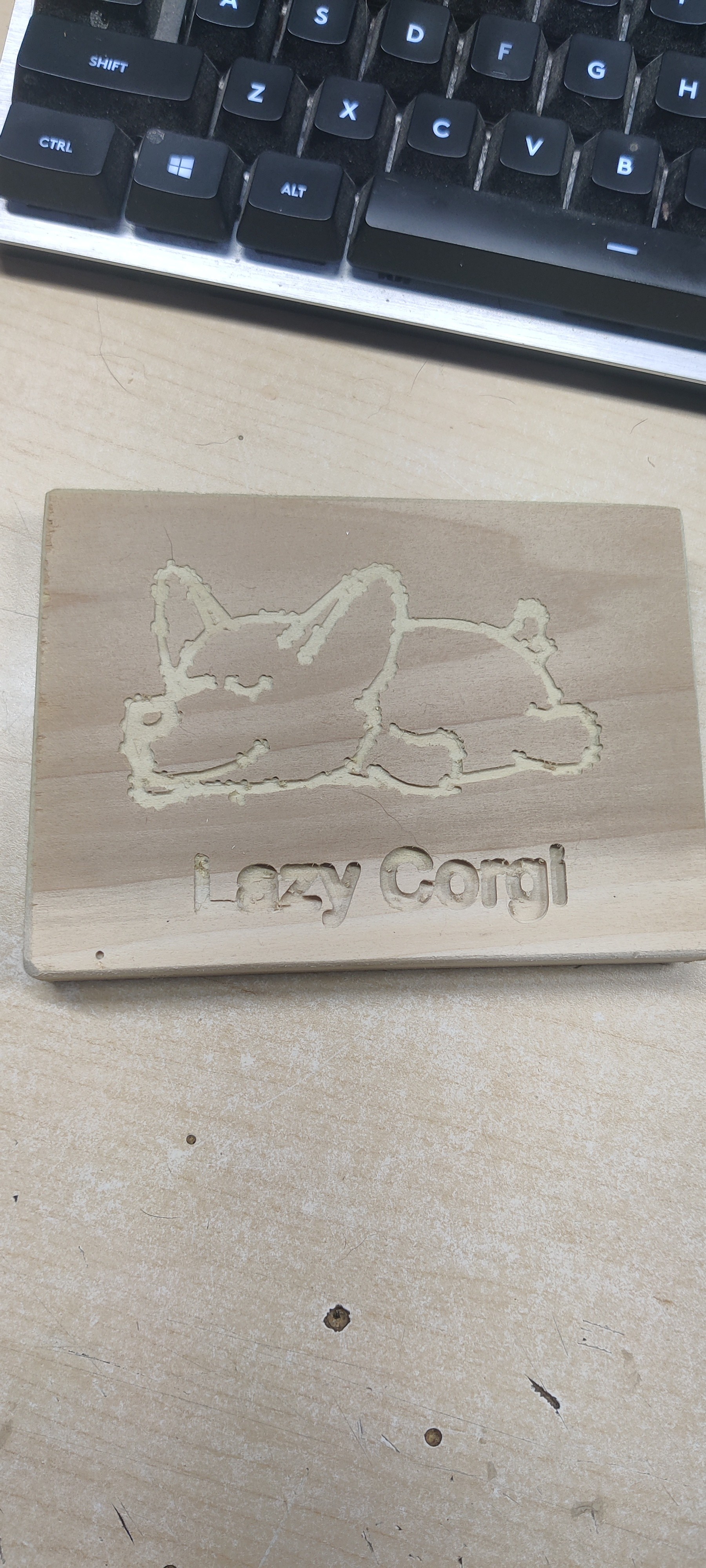
The “bumpy” lines were from the jpg conversion. It was a full color photo, so it wasn’t the best results.
So at this point, the hardware is pretty much done. I have a few very minor things I’d like to do, but they are more of a “nice to have” that uses LinuxCNC abilities. Now it’s going to be a matter of really learning the software side of things, but I have a fairly basic grasp of the flow already. I need to spend some time with Estlcam and learn all of it’s options.