V1E.com Forum
New MPCNC build in Iowa
Mostly Printed CNC - MPCNC
Your Builds
merrittgene
(Gene Merritt)
April 1, 2020, 12:13am
28
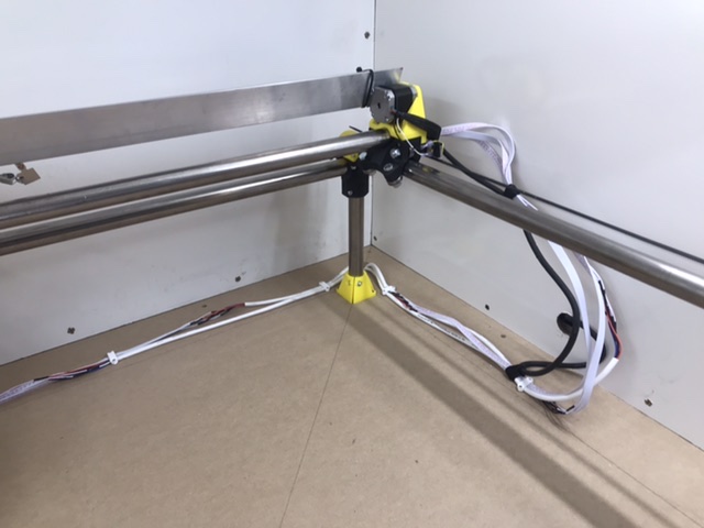
My cable management. I always assumed I’d use printed cable track, but decided I didn’t need it.
Slow progressing build from Germany
show post in topic