I did not see where your depth of cut per pass is. But it appears that the axis movement left and right in your picture that the grub screws are loose or the steps per mm are wrong.. try running a piece or foam.
Congrats though, nice figure eight
Grub screws are the set screws that hold the belt pulleys on the stepper motors. They tend to work loose if you forget to locktight them. Causing loss of steps as your cutting loads very. Quick way to check is use a marker and draw a line across the end of the pulley and shaft. Also make sure that the set screw ‘grub’ is on the flat of the shaft.
I reread your question . Your still final testing.
Have you checked your steps per mm on all three axis’s?
I’m away from the computer, but the basic idea is pick a distance close to the range of you axis.
For example 500 mm for the the X axis. You can do this 2 ways.
Zero the axis, mark that spot ,or use your smallest bit. Then move the axis 500 mm. Mark the second point and measure the distance with a steel ruler.
If you don’t have Ruler you trust, you can use even a shorter rule like 6" caliper with mm reading. Use 150 mm movement.
Repeat the steps for the Y and Z axis.
I will check in later on fixing the steps if they are off. It is documented here somewhere but I cannt remember where right now
Did you square the build first? Unsquare build can also cause ovals instead of circles.
You can check the steps/mm at that time as well. When you mark the 4 corners of the rectangle, in addition to measuring the diagonals to check for square, you can measure the perimeters of the axis to check for actual distance travelled vs expected distance.
Your circles are out by a lot, probably more than a steps/mm setting would cause. I would look for incorrect pulley size (24 teeth vs 16 teeth), excessive looseness in the core (does the core move if you try to jiggle it?), etc.
I completed reseating and adding locktight to all the grub screws even if they were tight when I pulled it apart.
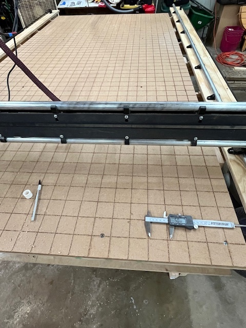
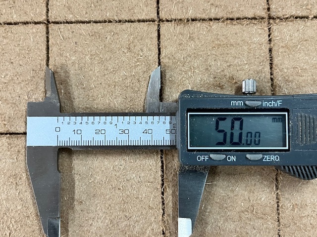
I did square the table a few weeks ago. I even leveled the table and cut reference lines. Last night I double checked my reference lines (50mm square) and they are good.
I am starting to think there is something going on with the Gantry.
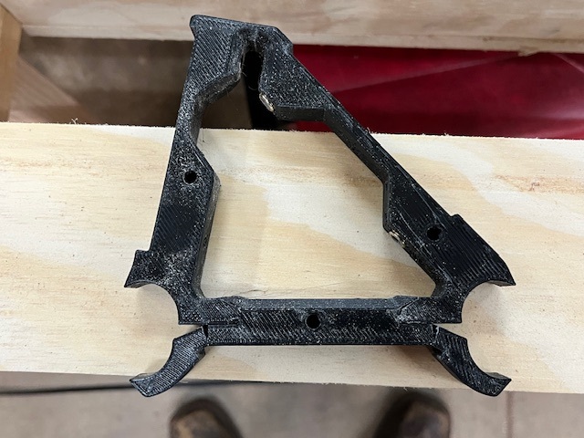
That brace looks like it was over tightened or over stressed. That’s a common problem with plastic parts. The parts are well designed, but we as builders are poorly calibrated for what appropriate torques are for them.
To be sure it isn’t a process problem, what settings did you use for printing your braces?
I don’t have a YR3 so this is out of my wheelhouse. I do wonder if may one of tubes is bowed enought to stress the brackets.
Something had to change thougth. Your grid looks great. Did you level before or after making the grid?
I ask because planeing the table can be a heavy stress load if you use too large of bit or hitting a high spot causing a moment of large depth of cut.
Lol, just saw @MakerJim comment. Makes more sence.
I purchased the entire kit 2 years ago. Its probably because they dried out. I have a friend currently printing me new ones at 60% infill.
I did level the table before doing the grid. When I did the level it was 1mm at a time until the entire table was flat at 6mm step over with a 1” surfacing endmill.
As for the grid, it was done with a 30 deg V-bit at 1mm increments down to 6mm.
With the X motor engaged to hold the core in place, if you grab the core and twist/jiggle it up/down, side to side, clockwise/counter clockwise, etc., does it move at all?
If so, you may need to tighten the core.
(Edit - Try this in the middle of the gantry, and at a few different locations closer to the edges)
If you draw a circle with a pen on paper does it come out okay?
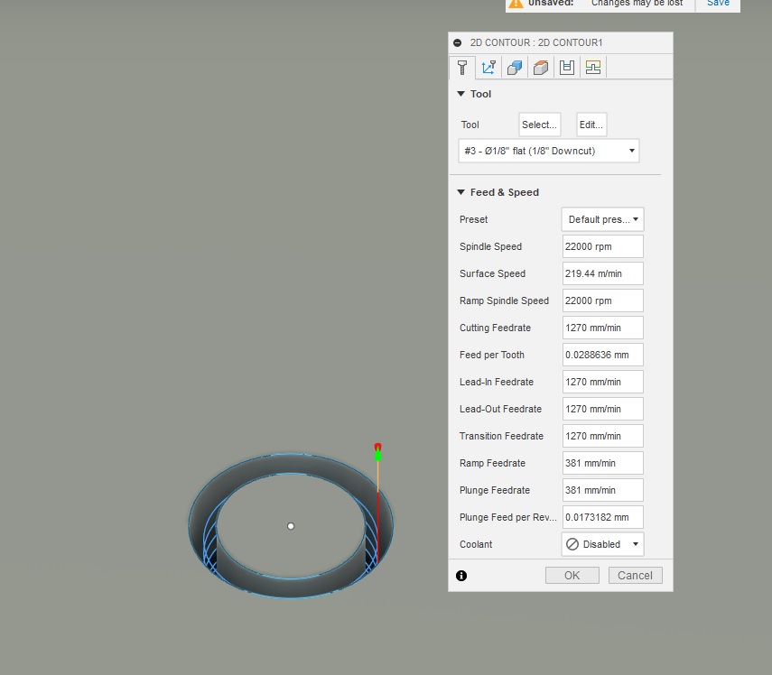
Looking at your fusion screenshot is it constantly spiralling down? I’m just thinking out loud but i wonder if that combined with a down cut bit is compacting the chips in the slot causing deflection.