New Laser CNC Build Proposal

This reminds me very much of @darxide’s portable mpcnc. I want one! Let me see if I can find the pictures he posted.

(edit) here it is Portable mpcnc? - #5 by darxide

2 Likes

Looky there! Getting closer, Kyle! I do prefer the seemingly more stable 4-leg style over the cantilever idea. I think I would also incorporate David’s z axis mod… I even have some leftover tubing from the lowrider2 build I just did. Although the 20/20 Extruded Aluminum is a little sexier! :wink: and probably lighter. At McMaster-Carr I have in my cart 4 x 2ft at about $33… can probably get all the legs and stuff from the hardware store and do it all with hex bolts (instead of T-Slot thingies.) I wonder if the linear bearlings/rails would be cooler than the rubber wheels… (albeit more expensive! I’ve seen some DIY rails on thingaverse or somewhere)

Feeling like I’m going to have to start prototyping and becoming tight with David (dkj4linux)!!! :slight_smile:

Now I’m not trying to steer anyone toward a competitor, but since the V1 shop doesn’t have aluminum extrusions, zyltech has pretty good pricing on 2020 bars. I got 10x1M pieces for around $80, if your looking to go that route. Then you’ll have some leftover to build more fun stuff! Just make sure you get the v-groove, not the t-slot. The inside bevel is different and most standard parts won’t fit quite right…ask me how I know :sweat_smile:

Wow Tim! I just closed my McMaster tab and am now shopping at Zyltech. Much easier for engineering since many/all stuff is related to building JUST these kindsa things! Thanks. (I do like leftover parts, too!)

Yeah, I know McMaster can be pretty spendy sometimes.

1 Like

Seems a lot of stuff is Out of Stock at Zyltech… bummer… I’ll pick this back up next week. I have some major yard sculpting I’m doing this weekend w/ a skid steer.

Thanks everyone

If you look at about message 199 on the Cantilevered thread, you will see where someone remixed it for a 4 leg design. I think he just duplicated the lower & upper frame plates to the other side & added another motor with belt. If you add the other side, you could probably simplify the upper & lower plates some more by just using 2020 beam on each side.

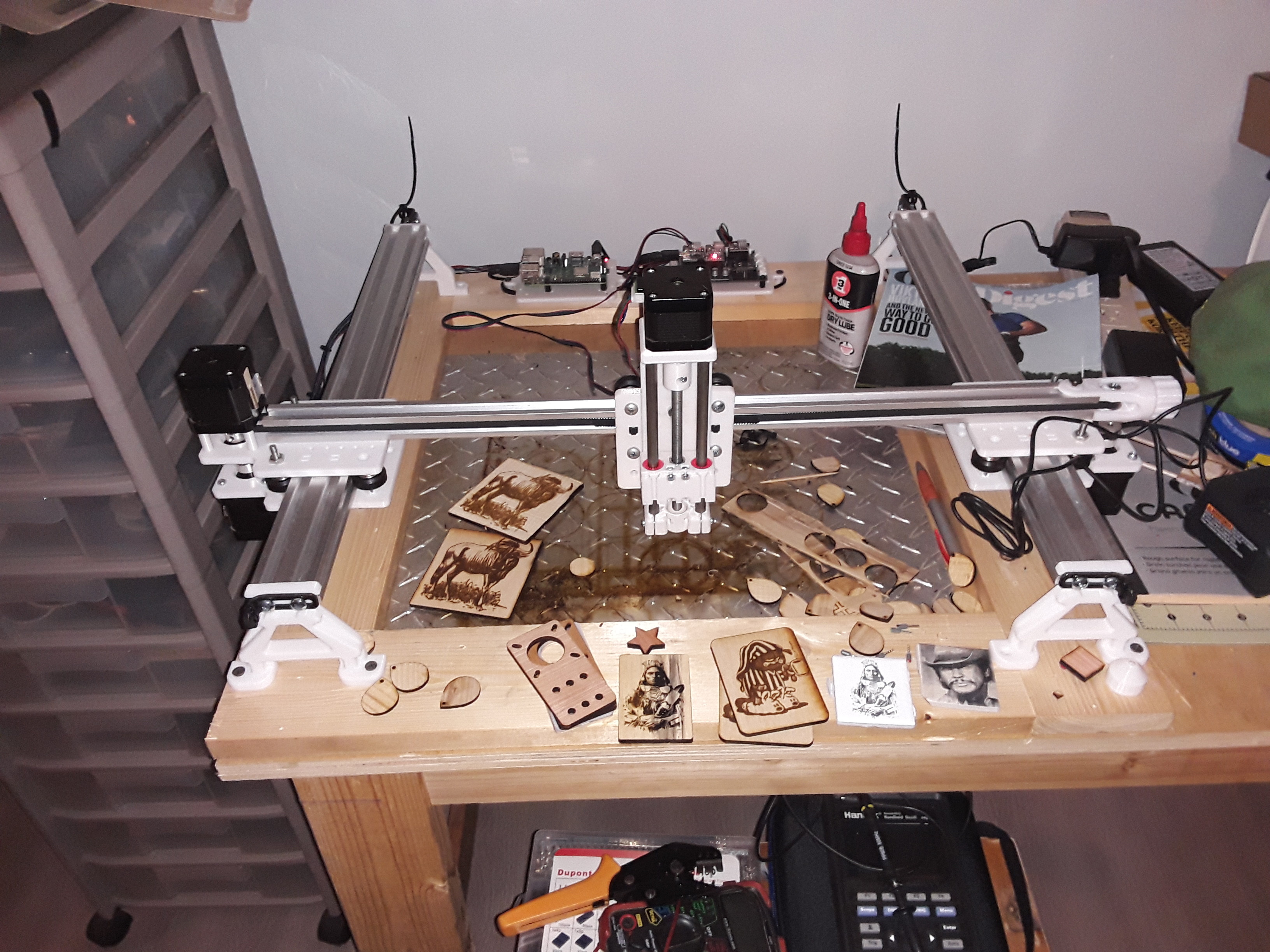
Similar to what @geodave just suggested, almost any of the cantilevered designs out there can be converted readily – and IMO improved – to a “4 leg design”. I had two slightly-modified ERC TimSav machines (a “minimalist” cantilevered design) set up for my TimSavX2 hot-wire machine – which I’ve since dismantled… so I took the two machines, mirrored them, and set them up with a shared gantry. Series connect the axis with two motors and you’ve now got your 4-legged machine…

I’ve been working on a new Z-axis and a laser module is missing in this photo…

– David

1 Like

I would like to point out that the impression you have of the cantilever being unstable is, I believe, unwarranted. Perhaps if you approach the idea from a routing or milling perspective then I might agree that it sounds sketchy but please remember there is zero load on the head, there is no measurable movement in a vertical direction over the range of either axis (providing you are not talking silly dimensions which, if you want to keep it portable, you are not)… and a single footprint does make the entire device more portable.
Davids example has the extra weight of the Z axis to support so is probably a necessary adaptation if a z axis is in your design parameters.

Nope not if you put the z axis on the edge. Check out the snapmaker it did well as a cantilevered machine.

Guys,

I wasn’t trying to imply cantilevered designs aren’t useful… they are. But I have built and played with the Edward Chew’s TimSav machine – a cantilevered design – and at the dimensions to handle 20"x30" foam sheet goods and with the minimalist structure… there is noticeable flex/play out at the end of the moving arm if you apply much pressure at all. Not that it isn’t “good enough” for needle-cutting foam for RC planes – and it is wonderfully portable – but the play is definitely there for anything more than the lightest of loads. Edward’s solution is to employ a “landing gear” to support the end of the beam… which works well enough when used on a clean surface. It’s perfect for carrying to your RC club’s monthly meeting…

But I also want a fully-implemented Z-axis on my machines… and I have several different, and differing-sized, laser modules… and I need an air-assist hose to the head… and… and…

All I was trying to point out was the relative ease of adding an extra driven rail – essentially identical to and mirroring the original – which captures and shares the common gantry beam. This results in a sturdier four-legged structure which fully supports the carriage/gantry and is easier to mod and “play with”… i.e. it better suits my need. Maybe yours, as well… :wink:

– David

3 Likes

Sure David…I wasn’t getting at your mods, I understand your rationale behind them but I just wanted to make the point about people might be thinking there was a problem with play in the vertical axis on a 12" Y axis and there isn’t in something that has no vertical load and low mass.

I took a look at the snapmaker…I got as far as the price tag…Thanks…but not my thing at all :slight_smile:

1 Like

Here’s the design and build process for further fab’s laser.

For portability I really like cantilevered designs. The one linked above has potential to be stiffened. With that long arm and landing gear, I imagine lateral torque on that arm (y axis of rotation) will be the biggest issue. To help reduce the lateral flex, that x carriage could be widened to provide more distance between the bearings. That carried far enough, should adequately support a laser without cropping x travel too much. Lasers don’t care if you are 1mm off or so, so vertical flex should be irrelevant, especially with that landing gear. One thing folks etching with lasers get after, is faster raster production. If you run the raster lines along the y axis, that cantilevered design is quite good. Rastering along the x might bring out the wag though.

Either way regarding more general design drivers, when you add “portable” to the requirements, you will pretty much have to start right off with compromising dimensional stability. To put that another way, a bridgeport is to a primo, like a primo is to a portable laser rig.

No I didn’t mean for you to buy one. I meant only to use it as an example of a cantilevered design that’s capable of not only lasering but 3d printing and light milling. So at least over short distances a cantilevered design can be very effective.

Hey guys! Hope everyone had a great weekend.

Wow… Lot’s a DD up there! I’ll need to catch up… some nice looking pics, too. Thanks!

David - that’s a COOL design. I hadn’t thought of laying the rails horizontal! I did started poking around and looking at linear bearings, which this design seems to replicate. Albeit, more expensive… but not totally out of the question.

Do you use little belt loops for the 2 Y axis motors?

Thanks, Dennis. The 2040 rails are laying horizontal because that’s its orientation in the cantilevered TimSav machine it’s based on… imagine the right-most rail gone and the gantry just cantilevered out in the air, to see it. The added axis is simply a mirrored version of the left-most rail setup and captures and supports the gantry end to allow heavier loads, such as my Z-axis mechanism and a laser module, to be mounted a bit more stably. The Y-axis motors are series-connected as with any dual-motor axis on MPCNC.

I’m planning to change out the 2020 gantry rail to 2040 (oriented vertically) to give a bit more stability to the Z-axis machanism. Then the entire machine will just be three lengths of 2040 V-slot.

Not sure what “belt loops” you’re referring to with the Y-axis motors… maybe a photo will help?

– David

1 Like

Yes, sir, that picture helped. I see now how the belt works for Y. Thanks, David. I’ll keep this design in mind as I engineer my idea.

I just got on a Linear Bearing kick and been look at thingiverse for stuff. There are some cool ideas for sure, and then I started thinking "what if I didn’t make the bearing out of abs/pla, but rather used some Oiless Self Lubricating bearing/bushing to slide up and down the tubes? Finding something with 1inch Inner bore is the trick… but something like:

image

I like that first one because I could design a housing thing that will hold it in place. Lot’s of folks also complained about lubricating… I thinker with old cars and transmissions and engine rebuilds… so that’s how I got to thinking about these. Basically, they would replace all the bearing rollers in the LR2 and just slide on the tubes. I suppose the only problem would be how tight the roundness tolerances are on that tubing. Might have to do some polishing on them! :slight_smile: (I didn’t opt for the stainless ones, either)

1 Like