The machine will skip steps before hurting itself. They aren’t needed for safety, and in they actually are being ignored when not homing, so they won’t affect safety either way.
I think most boards have the normal 6.
You would need to do some work to home in both directions. The normal home command doesn’t allow homing in a specific direction. You can configure it to go to the max or the min, but G28 only goes in one direction.
For sure. Although, you also get a huge benefit by just using a touch plate to home Z. Mesh leveling is kind of the next frontier, I think.
The standard microswitches have three connectors, but you only connect two. Sort of like a relay has three terminals, but you only use two. You connect ground to the common, and then the signal to one of the other two pins. One pin (Normally closed) will be connected to common until the button is pressed. The other (Normally Open) will only connect to the common when the button is pressed.
The other thing most people don’t realize (especially when coming from a 3D printer world). The home position is determined by the workpiece in CNC. It doesn’t matter where the lower left corner of the bed is. What matters is the lower left corner of your workpiece, or where you want to cut. So homing is normally useless. The two exceptions are when probing Z, to get a good start on the height, or when homing dual axis. Only while homing, if you have dual endstops, the axis can adjust one motor to align perfectly square to the other. After that, the endstops are ignored, and the motors move in lockstep.
I believe the reason that the firmware defaults
to only honoring the endstopss during homing is because there is a high probability of them falsely triggering during the job since folks are generally using unshielded wiring for them in as pretty electronically noisy environment.
Thanks for the comprehensive reply. I am still learning.
I’ve figured out the wiring for the end stops. I have to flip a wire over as the end stops are not wired the same way as the pinouts, though I may look to see if there is a way to reconfigure the pins on the min/max end stops. I have a mass of Dupont wires and am pinging M119 to see what happens.
I can see triggers and things like that, so it’s starting to come together.
Never thought about unshielded wiring. My background is a developer and even 5V is treated with deep suspicion by me Thats electwonics, I did Computer Science where 1’s and 1’s, 0’s are 0’s and keyboards are debounced elsewhere. Nowadays with quantum computing, 1’s are sometimes 1’s, sometimes 0’s and often every value in between.
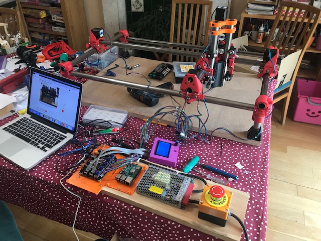
Tonight is checking that the end stops work correctly. Still on the dining table, still got lots of cables but getting there.
Downloaded a crown.gcode file and loaded it into Macpronterface anbd told it to print.
No homing set up as the motors on the dining room table
Motors started turning, the Z motor went up and down a small amount, X and Y motors kept turnng in unison but there did seem to be a pattern of activity.
I think it’s now working properly or at least as much as I can test on the dining room table. No idea if this translates (no pun intended) into the real world, but that’s a problem for a different night.
So things to do:
Rebuild the machine with the dual end stop mounts and chain mounts.
Build the support table from the scaffolding poles coming Friday. Sick to the back teeth of rubbish and cheap garage benchs so will build a decent strong and rigid one.
Cut down the second desktop that was sent by mistake when I brought a new office desk.
Cut (ahhh) the DuPont ends of the four end stops off and correctly rewire longer wires and the correct JTAG 3 pin sockets for the SKR V1.3 motherboard. Probably need sedation afterwards.
Make wiring harness for the four stepper motors and work out where to put it.
Rewire the whole control board as it’s too small.
Print a holder for a sharpie pen. Note not to use ball point pen. I do read the forums I do have a fabulous Rotring draughtmens set but thats not going anywhere near this until it’s all calibrated.
Get Octoprint setup on Raspberry Pi 4. It’s all done but not bothered to actually turn it on yet.
Find a sodding STL file that actually fits the RepRapFullDiscount LCD. On my third version and they have all been wrong as I think my LCD is 1mm wider than normal for some reason.
Print the drag chain claps. Lots of links and no clasps .
Find some software to use on Mac to test this out.
Learn what else is needed from the Marlin firmware. I think I just need to home at the start of every job and thats about it. What else?
For #4, rather than cutting the ends I’d just make extensions that convert from what you’ve got (Dupont?) to what you need (JTAG). Tape the dupont connectors together and hide them inside the conduits (assuming your limit switches are on the trucks) so they don’t get jostled around.
For #9, a file to enlarge the screen opening would be my choice over reprinting for hours.
I have a natural aversion to too many convertors and connectors in a wiring loom. I actually lose sleep thinking about the number of connections I have on my wiring harness and will probably cut and solder the wires up and then add the JTAG connector at the end. The thing is I"m not OCD (my brother is, so I know what it’s like), but for connectors I hate having too many and think they will come out or not work properly. My therapist just sighs as she puts the long sleeved pyjamas back on me …
I’ve struggled to find a file I can open and edit for the LCD display. Thingiverse drives me up the wall as people drop these files on with zero information such as sizes. They make the assumption that everybody knows what is needed and will not provide CAD files. They assume that every printer is the same, they assume that everybody has weird and wonderful screw lengths. Ahhh rant off.
My problem is that my knowledge of CAD is slightly less than my knowledge of kitten surgery, I mean, I dabble, doesn’t everyone, but I really have no idea about TinkerCAD or Fusion or whatever, so even simple things like enlarging a hole requires me to learn even more things when I just want to get the MPCNC up and working. Long term, my project will generate it’s own G-code and will not need a CAD front end, but that’s many months down the line. I’m still writing the software for that, but thats at least under my control…
One of the beauties of this machine and the way Ryan makes it available is that everyone can build to the level of “bullet-proof” that they find personally acceptable.
I realised I didn’t quite answer your question on adding convertors to my end stops. The other reason is that the current plugs on my end stops are JTAG, so simply extending them would mean putting a male TAG end on which is only supposed to be for boards. A Dupont connector would be easier but it’s still another plug.
To help me with the wiring harness, I’ve printed off a set of small spools and stand so I can pull four correctly coloured wires at a time and don’t create an n-dimensional mess. That’s the plan anyway …
I have four end stops to re-wire, and five stepper motors, a quick check on the number of tags show I only have around 300 of them so might need to get a large order into Amazon
I have now done a first fit build to check fit make sure things seems to work OK. I can use this for working out the wiring loom, lengths, directions etc.
I can move things up and down on the Z axis and the X and Y motors turn in the right directions with respect to each other.
I now have four belts set up, things seem to be moving quietly as well. I did have some chatter on a toothed gear but adjusted it out and it seems fine.
Which way is Z +ve supposed to be, away from the bed or towards the bed? The reason for this is to keep the default settings as much as possible with the Marlin firmware, so as new releases come out, I do as a few changes as possible,
+ve Z on my machine is down. I know it’s just a reversal of the connector but it offends me thats I got it wrong somewhere.
Also there must be a notional (0,0) on the bed. This must be consistent, e.g. if I wanted to write a name, it must have a correct direction otherwise the name would be reflected across an axis. On mine it must be the bottom left corner (aka the same as graph paper at school). Is this normal? Do CNC machines have a natural +ve direction?
If (0,0) is bottom left. this means my end stops must be top right, if (0,0) is bttom left. Which means I put the end stop pieces in the wrong direction. Got the maths wrong. Blast!
Another mistake Rats, this means I have to take the end pieces apart again.
Oh well, I’ll start taking it apart and putting it right.
Endstops are usually at the lower limits for X and Y, so they end up at 0,0. Z=0 is usually the top of the workpiece, so it also usually homes down, and you use a touchplate or something.
But! You can also use the machine for a few months without even worrying about endstops. So don’t get tok stressed about it. There is not end to the learning or configuration on this project.
Thanks,I was hoping that the logic of right and up was OK. I’ve changed the plates over now and did some quality checks around the Z axis.
I did a manual bed level check and and am around 1.0 - 1.5mm out across the depth of the bed. So at around (100,100) that’s my datum and considered to be 0. At 500mm x 500mm I’m around 1.5mm out. Not too bad I suppose given that it’s all hand made. However I will try and get that 1mm out of the system, though not quite sure how. My first inclination is to look at the auto bed levelling and put (somehow) a BLtouch V3.1 I happen to have lying around.
However, my second inclination is to sort out the X and Y axis first and get the end stops in. That makes more sense.
I’m printing a Sharpie holder as that’s probably the best thing to see how straight things are and if things are really square. I still think meshes are a good idea and will look at how Marlin or Klipper.js handles this lot.
 Thats electwonics, I did Computer Science where 1’s and 1’s, 0’s are 0’s and keyboards are debounced elsewhere. Nowadays with quantum computing, 1’s are sometimes 1’s, sometimes 0’s and often every value in between.


 Rats, this means I have to take the end pieces apart again.