@Carter thank you.
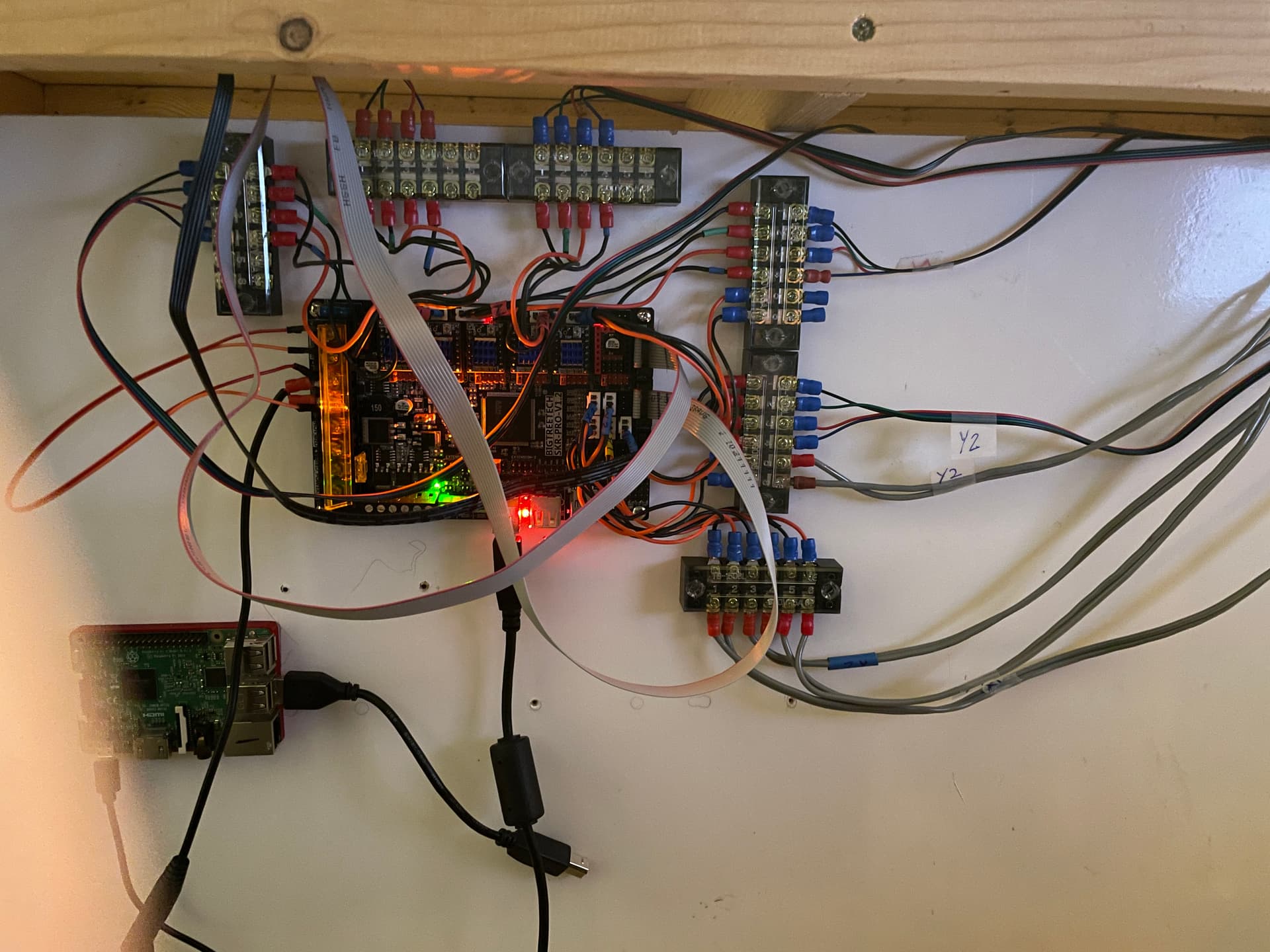
I’ve finally managed to get the wiring sorted out and mounted the SKR board etc. The wiring still needs to be tidied up, but as I will need to disconnect it all in order to move the table and machine out to my new shed when it arrives on March 1st, I’ll leave that little job for after then. It is still sitting in our dining room at the moment. I was going to use the Tape Measure Trick, but wasn’t happy with it at all so printed a nice drag chain instead, which took me a couple of days or so.
I also need to come up with a case for the display panel/joystick (yet to be wired in).
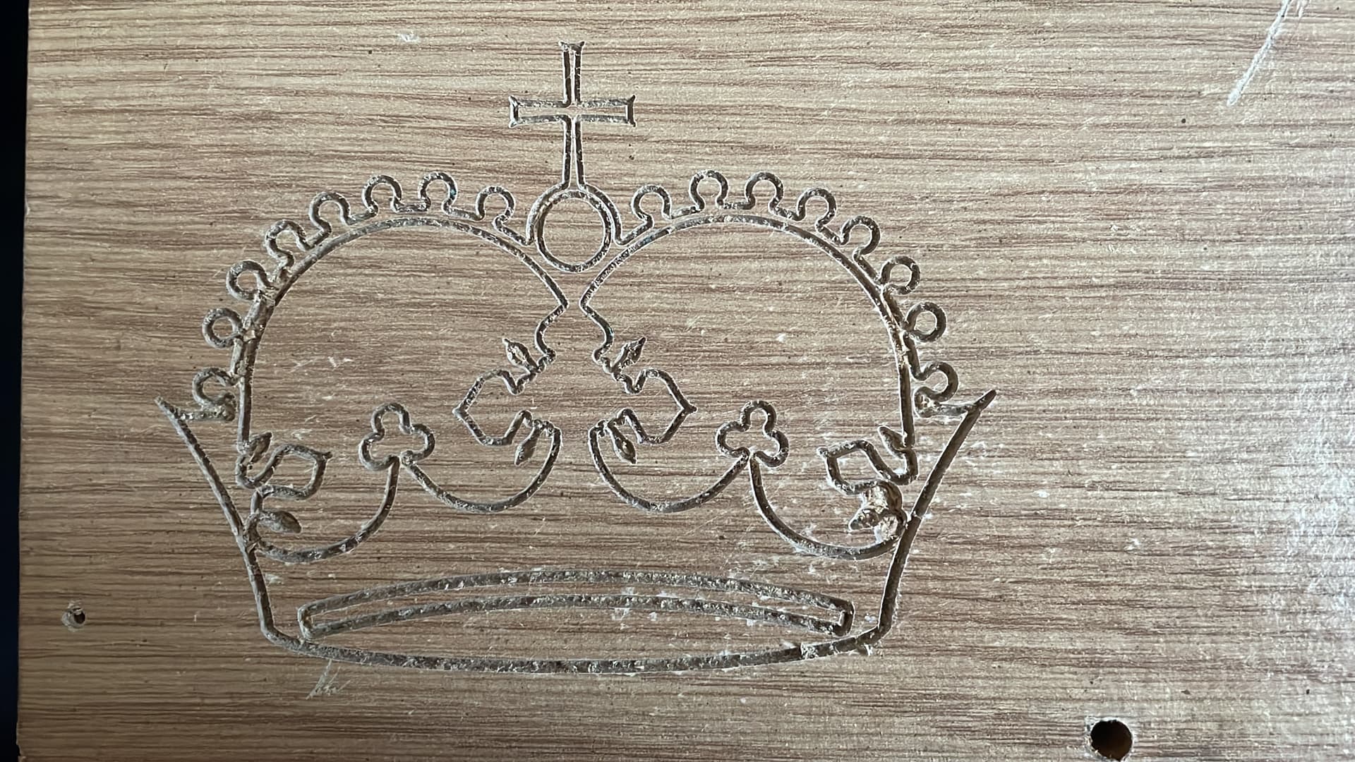
Anyway, after a little fault diagnosis (loose pin in the connector to the SKR) on the Z axis which sounded awful when I tried to move it after power up, it was time to see if I could get the ubiquitous Crown to appear as if by magic.
My initial efforts left the pen moving around in mid-air, despite me setting Z to zero with G92 Z0.0 while the pen tip was barely touching the paper. Turns out that I hadn’t set a deep enough DOC for the pen. I had 0.01mm set in Estlcam, but after re-reading Ryan’s instructions, changed it to 1.0mm and voilà, one crown was deposited on my paper. Well pleased with how it has turned out.


Now I need to buy some end mills, so I can get it dirty next month.
8 Likes
I like how realistic you are with yourself. I always say ill do it tomorrow or in the next few days but then nothing happens for a month. Might have to take notes from you and just start saying ill get to it in a month
Well, I can’t get it dirty until it’s out of the dining area (Mrs REB wouldn’t be too happy, I suspect). Therefore, it will be next month, as that’s when my new workshop/shed will be setup. Trust me, waiting is not by choice 
3 Likes
I was going to comment you must have a great spouse to leave that in the living area. I think one reason my wife supported my Primo build was knowing I’d be in the basement 
In your controller pic above, I see you have a raspberry pi. How are you using that with this build?
My wife is indeed a great lady - she must be to have put up with me for almost 42 years.
As for the dining room (actually an area off our L-shaped lounge), that rarely gets used for its primary function, but it is usually kept nice and tidy except when I have a largish project on the go. As my ‘hobby room’ is next to our bedroom (we live in a bungalow), for any 3D print that going take more than 12 hours (thinking MPCNC Core here), one of my 2 Prusa Mk3S printers gets moved on to the dining room table.
2 Likes
I haven’t actually connected the RPi (a 3B+) yet, but hopefully, it will eventually run Octopi and/or cncjs. I will probably use it to control some relays for various options too. It will depend on if my home Wi-Fi signal reaches my new shed - it should do.
1 Like
That’s great! Mine put up with me for 44 and counting. When I retired I kind of made the dinning table my office. Have a formal desk in another room but there is more room to stretch out on the dinning room table. Now she’s retired she has claimed the other half of the dinning room table. When we entertain everything get’s scooped into a bin and slid under the formal desk ![]()
2 Likes
OK, it’s been a while since last updated my build thread. It has taken me a bit (well, a lot) longer than I anticipated to get the MPCNC ‘dirty’.
My new shed/workshop was delivered and assembled on March 1st and I spent time sorting it out and getting it ready for use. That involved installing electrics and lighting etc. I also need to obtain some ‘furniture’ for storage and a working area.
Then, of course, it turned far too cold to do anything outside, so I left it be for a while longer. I did get some more work done on a dust collection system, 3D printing the parts etc.
I must say thank you to @Rloschy for the source file for his dust collector, which I was able to modify to accept M6 threaded rod, which I happened to have available.
Finally, I was able to get to the point where I could make sure everything was still square etc, and eventually use a pen to draw a horse’s head.
I spent some time in both EstlCAM and Fusion 360 learning the various settings, and I was eventually able to create a file that appears to do what I need and uploaded it to my Raspberry Pi connected to the MPCNC. I did an ‘air’ test first, and it seemed to go OK, so I found a gash piece of laminated chipboard and clamped it down. Next, I then ran the gcode and apart from one deviation (which I think I did when I bumped into something in my excitement), it turned out well. I didn’t go all the way through the chipboard, but the measurement of the circle and the spacing of the corner holes was spot on. In case anyone is wondering, the file is for a cutout in the end panel for a fan to cool the control board.
I still have a lot to do, like fixing the spoil board and making a clamping system, but I’m really pleased with how things are finally progressing.

Electrics added

Ready to go (just about).

Control board. The Raspberry Pi is on the other side and more easily accessible.

Overall view of my set-up.

The first cut. Not perfect, but I’m happy so far.
Thanks again to @Ryan for his great design and support for the MPCNC.
6 Likes
Congrats on your first cut and getting it dirty!
As per my other thread on having to replace the SKR Pro V1.2 control, my MPCNC is up and running again.
I’ve sorted my clamping out, and I’ve finally managed to cut The Crown. Just a gash piece of paper laminated chipboard, but it made me happy. 0.2 mm V-Bit, 1 mm deep - which was probably too deep as the cut has almost overlapped in a couple of places. The crown is 130 mm wide
It’s a steep learning curve, but I’m making progress.
2 Likes