Ok so i crash coursed Blender a bit. After serveral iterations. I was able to modify the trucks and z sepper mount to accommodate the nema23 steppers.
There were still a few minor things i missed and had to hot iron spots that were interfering with the idler pulleys. One big issue is the mounting deck for the truck steppers needs extending out. The reason , not at able to put nuts on the stepper screws closest the rails. I did make those holes smaller to make the screws bite better. But my guess is they will eventually strip. Every movement causes the steppers to tip away from the rail side. Couple that with feed pressure. And, I can see it failing.
I have built it, even with the suspect trucks. Took that to see its shortcomings.
I did have to thicken the mounting deck by about 7mm anf flip the timing pulley(set screws near the motor) for alignment. The shaft on the nema23’s are a bit shorter than nema17’s and this seemed the best solution.
Everything else looks good with the mechanical side. Electrical side, I’m not sure. The control board didn’t really come with a manual. After lots of Google-Fu, i think i have it figured out. If anyone can tell me whether this looks right or wrong id be very appreciative. When i get the trucks cleaned up with proper mounting I’ll offer up the remixed trucks and z mount.
Till then heres my wiring
1 Like
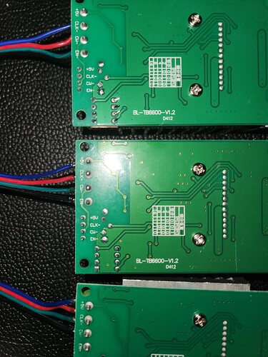
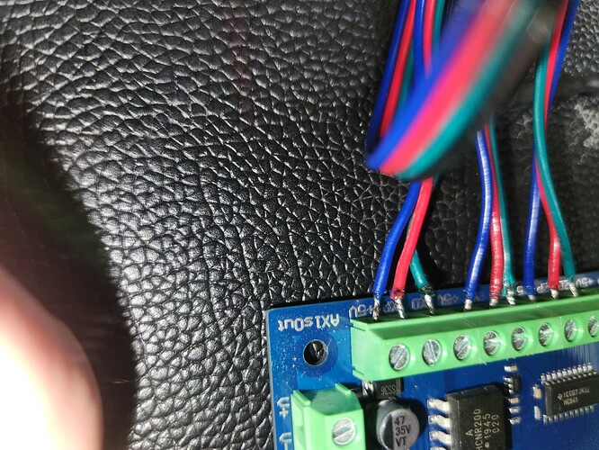
The pictures which maybe difficult to see, show
On Control board
Blue =5v
Red =axis pulse
Green =axis direction
On the Drivers
Blue =5v
Red = CLK-
Green = CW-
Black = Enable-
I have the blacks wired together and ran to a ground on the Control Board. Though from what I can find this may not be necessary. As drivers are usually enabled by default. But ran the wires anyway
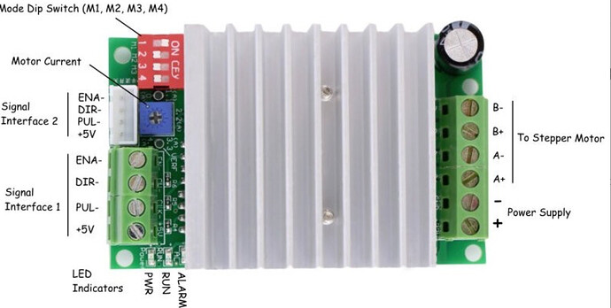
I’m not positive what the CLK- and CW- terminals are but I found some this photo of the TB6600 v1.2’s that I have. It seemed to indicate they are the pulse and direction terminals. Which is why I wired them as such. I’m just hoping someone can verify it for me


